 Na Liu
 Qian Zhao
- School of Environmental and Municipal Engineering, Qingdao University of Technology, Qingdao, China
Two-phase flow regimes were experimentally investigated during the entire condensation process of refrigerant R152a in a circular glass minichannel. The inner and outer diameters of the test minichannel were 0.75 and 1.50 mm. The channel was 500 mm long to allow observation of all the two-phase flow regimes during the condensation process. The experiments used saturation temperatures from 30 to 50°C, a mass flux of 150 kg/(m2·s) and vapor qualities from 0 to 1. The annular, intermittent and bubbly flow regimes were observed for the experimental conditions in the study. The absence of the stratified flow regime shows that the gravitational effect is no longer dominant in the minichannel for these conditions. Vapor-liquid interfacial waves, liquid bridge formation and vapor core breakage were observed in the minichannel. Quantitative measurements of flow regime transition locations were carried out in the present study. The experiments also showed the effects of the saturation temperature and the cooling water mass flow rate on flow regime transitions. The results show that the annular flow range decreases and the intermittent and bubbly flow ranges change little with increasing saturation temperature. The cooling water mass flow rate ranging from 38.3 kg/h to 113.8 kg/h had little effect on the flow regime transitions.
Introduction
Mini/Microchannels are widely used in many fields due to the advantages of enhanced heat transfer. The minichannels improve the system efficiency by reducing the air-side pressure drop and increasing the in-tube heat transfer coefficients. The minichannel heat exchangers also have the advantages of a smaller refrigerant charge, which leads to lower greenhouse gas emissions. Channels with hydraulic diameters ranging from 0.2 to 3 mm are defined as minichannels by Kandlikar and Grande (2003) for single-phase and two-phase fluid flows. Therefore, the test channel used in this study with a hydraulic diameter of 0.75 mm is classified as a minichannel. The flow regimes in minichannels differ from those in conventional channels because of the relative influences of gravity, shear stresses and surface tension.
Previous researchers, such as Alves (1954), Baker (1954) and Govier and Omer (1962), have given flow regime mappings for relatively large channels using air-water or air-oil mixtures. Suo and Griffith (1964) and Barnea et al. (1983) gave flow regime maps of air-water mixtures in small diameter circular channels. Investigations by several researchers (Damianides and Westwater (1988); Fukano et al. (1990)) showed that the flow regime maps of Mandhane et al. (1974), Taitel and Dukler (1976) and Weisman et al. (1979) in conventional channels failed to predict the flow regimes in small channels with hydraulic diameters ranging from 1 to 5 mm. Kawaji and Chung (2003) reviewed the previous research on adiabatic two-phase flows in narrow channels and performed new experiments. They concluded that the reduction of the tube diameter had a great influence on the flow regimes. Coleman and Garimella (1999) studied the effects of tube diameter and geometry on flow regimes and transitions of air-water flows in tubes with hydraulic diameters ranging from 1.3 to 5.5 mm. Then, Coleman and Garimella (2003) also conducted an experimental investigation of the two-phase flow mechanisms during condensation of refrigerant R134a in six round, square and rectangular tubes. Flow regimes of n-pentane during condensation in tubes with diameters of 10, 1.1 and 0.56 mm were experimentally investigated by Médéric et al. (2004). They found that the effect of gravity and capillary forces on the flow regimes were quite different for inner diameters less than 1 mm.
Two-phase flow regimes during condensation of FC-72 in 1 mm parallel, square micro-channels were experimentally observed by Kim et al. (2012). Five flow regimes were divided as smooth-annular, wavy-annular, transition, slug and bubbly flow. The smooth-annular flow and the wavy-annular flow were most prevalent among all flow regimes. Al-Zaidi et al. (2018) carried out flow visualization of HFE-7100 in a 0.57 mm rectangular multi-microchannel. Wang et al. (2017), Wang and Li (2018) studied two-phase flow regimes of R134a in 301.6 μm oval parallel microchannels. Nasrfard et al. (2019) experimentally studied the condensation heat transfer of R141b in intermittent flow regime within a smooth horizontal tube. Lei and Chen (2019) conducted numerical research on flow regimes of R134a based on the VOF approach. Jige et al. (2018) experimentally observed the two-phase flow characteristics of R32 in horizontal multiport rectangular minichannels with hydraulic diameters of 0.5 and 1.0 mm. A new prediction method of flow regimes for multiport minichannels, considering channel size, was developed based on the experimental results. Keniar and Garimella (2021) studied the intermittent flow of R134a during condensation in circular microchannels. Li et al. (2021) experimentally studied the flow pattern change in horizontal minichannels under electric field force. The results showed that the bubble behavior was suppressed by the electric field force.
Recent increased attention to environmental issues has brought substantially more stringent requirements for refrigerants in air-conditioning and refrigeration applications. The transition from CFCs to HCFCs and to HFCs has reduced the environmental impact of refrigeration systems. Since R22 is widely used in domestic air conditioners in China, the substitution is quite urgent. Although HFCs have zero ozone depletion potential (ODP), many have high global warming potentials (GWP). Therefore, much effort is being focused on finding alternative refrigerants to conventional HFCs.
Table 1 listed the thermophysical and environmental characteristics of R22, R134a and R152a. The GWP of R152a is an order of magnitude smaller than that of R22 and R134a. The thermal conductivity, latent heat of vaporization and surface tension of R22 and R134a are lower than R152a. The heat transfer performance of R22, R134a and R152a during condensation was theoretically investigated by Wang and Rose (2011). The results showed that R152a had better heat transfer performance than R22 and R134a. The experimental research of Liu and Li (2015) also showed that the heat transfer coefficients during condensation of R152a were greater than those of R22. Although R152a is a potential substitute for R22, no experimental study has been carried out on the flow regimes during the entire condensation process in minichannels.
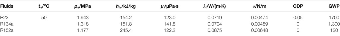
TABLE 1. Thermophysical and environmental properties of R22, R134a and R152a.
Experimental Methods
Experimental Rig
Figure 1 shows a schematic of the experimental rig established for flow regime observation. The rig consists of one refrigerant and two cooling water loops. The experimental apparatus consists of a refrigerant and two cooling water circuits. The subcooled refrigerant in the reservoir is filtered, circulates through the magnetic-driven gear pump that can be adjusted by the frequency converter, and then flows through the Coriolis effect mass flowmeter. The mass flow rate is controlled by a bypass loop. The refrigerant in the vapor generator is heated to saturation by adjusting the electric heating power. The liquid-level meter is used to monitor the liquid phase level and keep it steady in the vapor generator. The saturated fluid then flows into the circular glass channel in the test section. The vapor refrigerant is fully condensed by the cooling water in the test section. After the test section, the refrigerant flows to the post-condenser, where it is further subcooled, and finally returns to the reservoir. The operating pressure in the refrigerant circuit is controlled by adjusting the electric heating power of the heater installed in the reservoir.
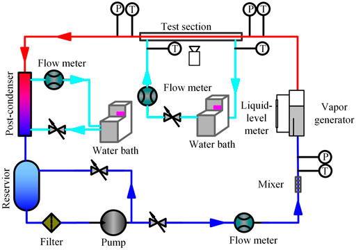
FIGURE 1. Schematic of the experimental rig.
The purity of the refrigerant R152a provided by the manufacturer is larger than 99.9%. The measures are taken to ensure that the vapor contains no incondensable gas: the experimental system is vacuumed for half an hour to remove the air; some R152a is filled into the system; vacuum the system again. The filling and evacuating measures were repeated several times to ensure that the system contained as little incondensable gas as possible. After the above measures, R152a was filled into the system.
The refrigerant and cooling water temperatures are measured using PT100 resistance thermometers. All PT100 resistance thermometers are calibrated using a 6,020 Series high precision calibration bath before the experiments. Trafag 8,251 pressure sensors are used to measure the refrigerant pressures through 1.0 mm pressure taps. Two Coriolis mass flowmeters are used to measure the mass flow rates of the refrigerant and the cooling water in the test section, respectively. The flow regimes during condensation are observed by an imaging system as shown in Figure 2. A MV-VS078FC industrial CCD camera is used with a resolution of 1,024 × 768 pixels, a light sensitivity of 0.01 LUX and a shutter speed of 1 × 10⁻⁴ s. Experimental data are collected by an Agilent 34970A acquisition system.
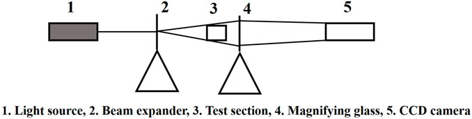
FIGURE 2. Imaging system.
Test Section
The test section was a counter flow tube-in-tube condenser as shown in Figure 3. The refrigerant was condensed inside the glass test tube by the cooling water flowing in the cooling water jacket. The test tube was a circular glass minichannel with inner and outer diameters of 0.75 and 1.50 mm. The test tube was 500 mm long to allow observation of all the flow regimes during the condensation process in the test section. A special external structure is required to bear the stress generated during the installation of the test section to ensure that the glass tube is not damaged. Copper joints with internal and external treads are connected to both ends of the glass tube in order to provide a labyrinth seal for the glass tube. Raw tape is wrapped on the ends of the glass tube and the adhesive is evenly covered on the raw tape to ensure the tightness and pressure resistance of the connection. The nuts filling with the mixture of raw tape and adhesive are installed under small squeeze force to avoid putting lateral stress on the glass tube. Two copper plates are installed outside the glass tube to transfer the torsion and bending stress generated during the installation process of the test section. Two glass sheets are installed on the front and back of the test section to offer the visual observation of the flow regimes. The cooling water jacket was rectangular, 500 mm long with the hydraulic diameter of 16 mm. The top and bottom materials of the cooling water jacket were copper, while the front and rear materials were glass for the observations. Two hard rubber supports were installed in the cooling water jacket to support the long glass tube. During the experiments, the cooling water jacket was exposed to the atmosphere which was around 18°C.
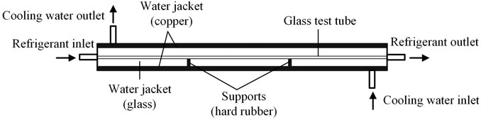
FIGURE 3. Test section schematic.
The locations of the flow regime transitions during the entire condensation process were recorded to investigate the effects of the experimental conditions on the flow regime transitions. The location determination method is shown in Figure 4. The coordinate measurement device consisted of a ruler placed parallel to the test section, the viewing device and the separation blade perpendicular to the test section. The ruler reading at the blade’s left side was regarded as the local coordinate of the observed flow regime element.
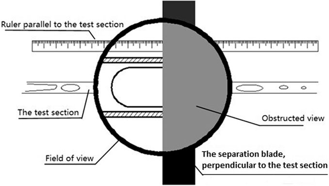
FIGURE 4. Determination of the flow regime transition locations.
Uncertainty Analysis
The experimental uncertainties of the parameters are listed in Table 2. The thermophysical properties of R152a are obtained through the REFPROP 9.0 software (Lemmon et al., 2010).
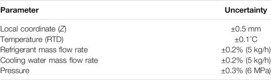
TABLE 2. Uncertainties of the measured parameters.
Results and Discussion
In order to verify the reliability of the experimental system, single-phase heat transfer experiments were carried out in a 1.09 mm circular tube by Zhang et al. (2012). Experimental pressure drops agree well with the predicted results of equation Blasius (1908), and the average deviation and root mean square deviation are within 1.7 and 8.8%, respectively. Experimental heat transfer coefficients agree well with the predicted results of correlation Gnielinski (1976), and the average deviation and root mean square deviation are within 4.1 and 12.8%. The deviation of the heat transfer rate between the refrigerant and the cooling water is within ±5%. The heat loss in the test section was within ±0.25 W. Single-phase verification experiments show that the experimental apparatus is reliable and can be used for two-phase flow and condensation heat transfer experiments.
Flow Regimes During Condensation
The test section for the flow regime experiments was long enough to observe the entire condensation process. The annular, intermittent and bubbly flow regimes were observed in the present study as listed in Table 3 as the vapor quality was reduced, which differs from the results of Coleman and Garimella (2003). In Coleman and Garimella’s study, the flow regimes were categorized into four different flow regimes as intermittent flow, wavy flow, annular flow and dispersed flow. The relative importance of gravity, surface tension and interfacial shear stress differs for different flow regimes and transitions. In the present study, the interfacial shear stress is not large enough to entrain liquid droplets into the vapor core for G = 150 kg/(m2·s); therefore, the mist flow regime is not observed. In addition, the absence of the stratified flow regime suggested that gravity was no longer dominant for the 0.75 mm diameter tube. At low vapor qualities, the dispersed flow regime with bubbles dispersed across the tube cross section was also not observed in the study.
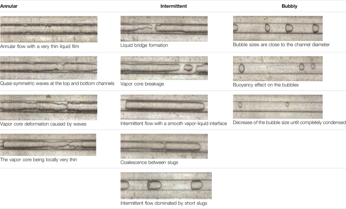
TABLE 3. Flow regimes during condensation of R152a in a 0.75 mm circular minichannel.
Annular Flow Regime
The annular flow regime occurred at the very beginning of the condensation process with the vapor flowing in the channel core and a uniform thin liquid film flowing along the channel periphery. Vapor-liquid interfacial waves were caused by the shear stress between the two phases flowing with different velocities. There was no distinct difference between the top and bottom channel wave strengths because the liquid film was quite thin. The interfacial shear stress dominants at this stage.
The liquid film became thicker as the condensation proceeded. Gravity caused the liquid film to be thicker at the bottom of the channel than at the top. Therefore, the interfacial waves were no longer uniform around the channel periphery. The wave frequency decreased while the wave amplitude increased. According to Barnea et al. (1983), the current flow pattern can be subdivided as the wavy-annular flow regime which still belongs to the annular flow regime.
The interfacial waves then caused the vapor core to deform with the deformation becoming stronger as the liquid film became thicker. Two kinds of interfacial waves were observed during the wavy-annular flow regime. One occurred when the wave crests at the top and bottom channels locally reduced the vapor core size. The other occurred when the wave crests at the top and bottom channels were not at the same location and deformed the vapor core channel.
Three kinds of vapor core deformations were frequently observed during the wavy-annular flow regime as the vapor quality was reduced for the same refrigerant saturation temperature, cooling water mass flow rate and inlet cooling water temperature. Any vapor core deformations often led to the formation of liquid bridges and finally vapor core breakage. The liquid film thickness at the top and bottom channels both increased causing vapor core deformation. The liquid film thickness at the bottom channel increased faster than that at the top channel. Strong interfacial waves caused several vapor core deformations in a short channel. Vapor core deformations indicate the occurrence of the surface tension effect. The combination of interfacial shear stress and surface tension will cause the transition from annular flow to intermittent flow with the increase of the liquid film thickness.
Intermittent Flow Regime
The flow regime transitioned from wavy-annular flow to intermittent flow as the liquid film became thicker and the interfacial waves were strong enough to form liquid bridges across the vapor core which broke the vapor core. The intermittent flow regime consisted of vapor slugs in the channel core with a liquid film coating the channel wall around the vapor slugs. Three types of liquid bridge formations and vapor core breakages corresponding to the vapor core deformations were observed during the intermittent flow regime with decreasing vapor quality for the same refrigerant saturation temperature, cooling water mass flow rate and inlet cooling water temperature. 1) Liquid films at the top and bottom of the channel become thicker which reduces the vapor core cross-sectional area. The top and bottom liquid films eventually join and the vapor core is broken into two parts. 2) The liquid bridge is caused by the liquid film thickness increasing at the bottom of the channel. The liquid bridge forms when the bottom liquid film is thick enough to reach the top liquid film. The resulting slug end is close to the top wall which creates a small thermal conduction resistance through the liquid film there and a high condensation rate. The slug end then condenses quickly and the liquid bridge forms. 3) Two liquid bridges forming in a short channel due to frequent strong waves. The vapor core is broken into several slugs. The short slug flows and condenses, which implies that short slugs also occur during the early period of the intermittent flow regime in addition to later on. Since short slugs appear for only a short time due to the high condensation rate, the intermittent flow regime is dominated by long slugs during the early period.
During the intermittent flow regime, the slug length decreases and the liquid bridge width increases due to condensation. Surface tension dominants among the three forces for the intermittent flow. However, slug coalescence due to the flow velocity difference was also observed. The coalescence frequency between slugs is much smaller than the breakage frequency of the slugs. Slug coalescence has little effect on the condensation heat transfer. In general, the slug lengths decrease as the condensation continues during the intermittent flow regime. The slug surface becomes very smooth implying the surface tension effect.
Bubbly Flow Regime
The flow regime transits to the bubbly flow regime when the bubble sizes are almost equivalent to the channel diameter. Gravity, surface tension and interfacial shear stress work simultaneously at this stage. The liquid film thickness around the channel increases and the condensation rate decreases with the decrease in the vapor quality. Bubbles rise to the top channel due to buoyancy as the bubbles become smaller. The movement of bubbles is mainly affected by gravity. The liquid films are thin near the top channel so the conduction thermal resistance is small as the bubbles rise to the top channel. Therefore, the bubbly flow regime does not last for long and the flow finally transits to all liquid.
Effects of the Experimental Conditions on the Flow Regime Transitions
Effect of Saturation Temperature
Thermophysical properties especially the vapor-liquid density difference were directly influenced by the refrigerant saturation temperature. On the one hand, the vapor-liquid density difference decreases with increasing saturation temperature resulting in smaller vapor core shear stress and weaker waves for which condition liquid bridges are not easy to form. On the other hand, the heat transfer temperature difference between the refrigerant and the cooling water increases with increasing the refrigerant saturation temperature for constant inlet cooling water temperature and mass flow rate resulting in faster condensate film growth for which condition liquid bridges are easy to form. The saturation temperature effect on the flow regime transitions depends on the relative size of the above two factors.
The flow regime transitions were identified as the annular-intermittent flow regime transition which occurs when liquid bridges form, the intermittent-bubbly flow regime transition which occurs when most bubble sizes are equivalent to the channel diameter and the bubbly-full liquid flow regime transition which occurs when the small bubbles disappear completely. Figure 5 shows the effect of saturation temperature on the flow regime transitions for a constant cooling water mass flow rate of 61.0 kg/h with an inlet cooling water temperature of 15°C. Z represents the appearance of the flow regime along the test section. Zc represents the length needed for the entire condensation process for each experimental condition.
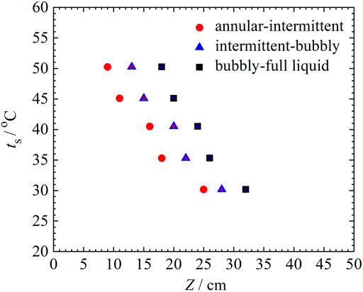
FIGURE 5. Effect of saturation temperature on flow regime transitions.
Figure 5 show that flow regime transitions advance with increasing saturation temperature. The length for the entire condensation process decreases from 32.0 to 18.0 cm with saturation temperatures increasing from 30 to 50°C. The range of the annular flow regime decreases while the ranges of the intermittent and bubbly flow regimes change little with increasing saturation temperature or the temperature difference between the saturation temperature and the wall temperature. Thus, these results indicate that the heat transfer during condensation mainly occurs during the annular flow regime. The condensation process becomes faster and the condensation length needed for the same refrigerant mass flow rate becomes shorter with increasing the refrigerant and cooling water temperature difference. However, the saturation temperature has little effect on the heat transfer rates during the intermittent and bubbly flow regimes for constant cooling water mass flow rate and inlet cooling water temperature.
Figure 6 shows the effect of saturation temperature on the relative lengths of the flow regimes. The results show that the annular flow regime is dominant accounting for 75% for the total condensation range with the intermittent and bubbly flow regimes accounting for 11 and 14% for the saturation temperature of 30°C. The proportions of the annular, intermittent and bubbly flow regimes are 31, 30 and 39% for the saturation temperature of 50°C. Therefore, the actual ranges and the proportions of the annular flow regime both decrease with increasing saturation temperature. However, the actual ranges of the intermittent and bubbly flow regimes change little and the proportions increase with increasing saturation temperature.
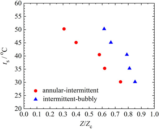
FIGURE 6. Effect of saturation temperature on relative lengths of the flow regimes.
Effect of the Cooling Water Mass Flow Rate
Figure 7 shows the effect of the cooling water mass flow rate (ranging from 38.3 kg/h to 113.8 kg/h) on the flow regime transitions for a saturation temperature of 45°C and an inlet cooling water temperature of 20°C. The results show that flow regime transitions advance slightly with increasing the cooling water mass flow rate. For the mass flux of 150 kg/(m2·s), the flow regimes and transitions are significantly affected by the temperature difference between the saturation temperature of the refrigerant and the cooling water. However, the cooling water mass flow rate of 38.3 kg/h is high enough for the condensation heat transfer and further increasing the cooling water mass flow rate has little effect on flow regime transitions in the present study. In further research, different mass fluxes of the refrigerant should be experimentally studied to analyzed the effect of the cooling water mass flow rate.

FIGURE 7. Effect of the cooling water mass flow rate on flow regime transitions.
Conclusion
The flow regimes during condensation of R152a were investigated experimentally in a 0.75 mm circular glass minichannel. The experiments used saturation temperatures from 30 to 50°C, a mass flux of 150 kg/(m2·s) and vapor qualities from 0 to 1. The results show that:
The annular, intermittent and bubbly flow regimes were observed during the condensation process. The absence of the stratified flow regime shows that the gravity effect is no longer dominant in the minichannel. The observations show the importance of the vapor-liquid interfacial waves, the vapor core deformations and the liquid bridge formations. The effects of the saturation temperature and the cooling water mass flow rate on the flow regime transitions were also investigated. Quantitative measurements of flow regime transition locations were carried out. The results show that the actual ranges and the proportions of the annular flow regime both decrease with increasing saturation temperature. However, the actual ranges of the intermittent and bubbly flow regimes change little and the proportions increase with increasing saturation temperature. The cooling water mass flow rate is significantly high and has little effect on the flow regime transitions in the present study.
Data Availability Statement
The raw data supporting the conclusions of this article will be made available by the authors, without undue reservation.
Author Contributions
NL established the experimental system, carried out the experiments and wrote the first submission of the paper. QZ and ZL gave a lot of help during the experiments. All authors contributed to the article and approved the submitted version.
Funding
This work is supported by the National Natural Science Foundation of China (Grant No. 51904325).
Conflict of Interest
The authors declare that the research was conducted in the absence of any commercial or financial relationships that could be construed as a potential conflict of interest.
Publisher’s Note
All claims expressed in this article are solely those of the authors and do not necessarily represent those of their affiliated organizations, or those of the publisher, the editors and the reviewers. Any product that may be evaluated in this article, or claim that may be made by its manufacturer, is not guaranteed or endorsed by the publisher.
Abbreviations
D, tube diameter, mm; Dh, hydraulic diameter, mm; hlv, latent heat, J/kg; ts, saturation temperature, oC; ps, saturation pressure, MPa; Z, flow regime coordinate, cm; Zc, length of the entire condensation process, cm Greek symbols; α, aspect ratio; λ, thermal conductivity, W/(m·K); μ, viscosity, Pa·s; σ, surface tension, N/m.
References
Alves, G. E. (1954). Cocurrent Liquid-Gas Flow in a Pipe-Line Contactor. Chem. Eng. Process 50, 449–456.
Al-Zaidi, A. H., Mahmoud, M. M., and Karayiannis, T. G. (2018). Condensation Flow Patterns and Heat Transfer in Horizontal Microchannels. Exp. Therm. Fluid Sci. 90, 153–173. doi:10.1016/j.expthermflusci.2017.09.009
Barnea, D., Luninski, Y., and Taitel, Y. (1983). Flow Pattern in Horizontal and Vertical Two Phase Flow in Small Diameter Pipes. Can. J. Chem. Eng. 61 (5), 617–620. doi:10.1002/cjce.5450610501
Coleman, J. W., and Garimella, S. (1999). Characterization of Two-phase Flow Patterns in Small Diameter Round and Rectangular Tubes. Int. J. Heat Mass Transfer 42 (15), 2869–2881. doi:10.1016/s0017-9310(98)00362-7
Coleman, J. W., and Garimella, S. (2003). Two-phase Flow Regimes in Round, Square and Rectangular Tubes during Condensation of Refrigerant R134a. Int. J. Refrig. 26 (1), 117–128. doi:10.1016/s0140-7007(02)00013-0
Damianides, C. A., and Westwater, J. W. (1988). “Two Phase Flow Patterns in a Compact Heat Exchanger and in Small Tubes,” in Second UK National Conference on Heat Transfer, Glasgow, September 14–16, 1988 (London: Mechanical Engineering Publications), 1257–1268.
Fukano, T., Kariyasaki, A., and Kagawa, M. (1990). Flow Patterns and Pressure Drop in Isothermal Gas-Liquid Concurrent Flow in a Horizontal Capillary Tube. Trans. Jpn. Soc. Mech. Eng. B 4 (528), 153–161. doi:10.1299/kikaib.56.2318
Gnielinski, V. (1976). New Equation for Heat and Mass Transfer in Turbulent Pipe and Channel Flow. Int. Chem. Eng. 16 (2), 359–368.
Govier, G. W., and Omer, M. M. (1962). The Horizontal Pipeline Flow of Air-Water Mixtures. Can. J. Chem. Eng. 40 (3), 93–104. doi:10.1002/cjce.5450400303
Jige, D., Kikuchi, S., Eda, H., Inoue, N., and Koyama, S. (2018). Two-phase Flow Characteristics of R32 in Horizontal Multiport Minichannels: Flow Visualization and Development of Flow Regime Map. Int. J. Refrig. 95, 156–164. doi:10.1016/j.ijrefrig.2018.09.005
Kandlikar, S. G., and Grande, W. J. (2003). Evolution of Microchannel Flow Passages--Thermohydraulic Performance and Fabrication Technology. Heat Transfer Eng. 24, 3–17. doi:10.1080/0145763039011607710.1080/01457630304040
Kawaji, M., and Chung, M. Y. (2003). “Unique Characteristics of Adiabatic Gas-Liquid Flows in Microchannels: Diameter and Shape Effects on Flow Patterns, Void Fraction and Pressure Drop,” in ASME International Conference on Microchannels & Minichannels, Rochester, NY, April 24, 25, 2003, 115–127. doi:10.1115/icmm2003-1013
Keniar, K., and Garimella, S. (2021). Lagrangian Modeling of Intermittent Flow Condensation in Circular Micro- and Mini-Channels. Int. J. Heat Mass Transfer 164 (5), 120586. doi:10.1016/j.ijheatmasstransfer.2020.120586
Kim, S.-M., Kim, J., and Mudawar, I. (2012). Flow Condensation in Parallel Micro-channels - Part 1: Experimental Results and Assessment of Pressure Drop Correlations. Int. J. Heat Mass Transfer 55 (4), 971–983. doi:10.1016/j.ijheatmasstransfer.2011.10.013
Lei, Y., and Chen, Z. (2019). Numerical Study of Condensation Flow Regimes in Presence of Non-condensable Gas in Minichannels. Int. Commun. Heat Mass Transfer 106, 1–8. doi:10.1016/j.icheatmasstransfer.2019.04.001
Lemmon, E. W., Huber, M. L., and Mclinden, M. O. (2010). Nist Standard Referencedatabase 23: Reference Fluid Thermodynamic and Transport Properties-Refprop. 9.0.
Li, H.-W., Wang, Y.-C., Du, C.-H., and Hong, W.-P. (2021). Analysis of Flow Pattern Change in Horizontal Mini-Channel under Electric Field Force. Int. Commun. Heat Mass Transfer 121, 105081. doi:10.1016/j.icheatmasstransfer.2020.105081
Liu, N., and Li, J. (2015). Experimental Study on Condensation Heat Transfer of R32, R152a and R22 in Horizontal Minichannels. Appl. Therm. Eng. 90, 763–773. doi:10.1016/j.applthermaleng.2015.07.062
Mandhane, J. M., Gregory, G. A., and Aziz, K. (1974). A Flow Pattern Map for Gas-Liquid Flow in Horizontal Pipes. Int. J. Multiphase Flow 1 (4), 537–553. doi:10.1016/0301-9322(74)90006-8
Médéric, B., Miscevic, M., Platel, V., Lavieille, P., and Joly, J.-L. (2004). Experimental Study of Flow Characteristics during Condensation in Narrow Channels: the Influence of the Diameter Channel on Structure Patterns. Superlattices Microstruct. 35 (3-6), 573–586. doi:10.1016/j.spmi.2003.11.008
Nasrfard, H., Rahimzadeh, H., Ahmadpour, A., and Naderan, H. (2019). Experimental Study of Condensation Heat Transfer for R141b in Intermittent Flow Regime within a Smooth Horizontal Tube. Exp. Therm. Fluid Sci. 105, 109–122. doi:10.1016/j.expthermflusci.2019.03.019
Suo, M., and Griffith, P. (1964). Two-Phase Flow in Capillary Tubes. J. Basic Eng. 86 (3), 576–582. doi:10.1115/1.3653176
Taitel, Y., and Dukler, A. E. (1976). A Model for Predicting Flow Regime Transitions in Horizontal and Near Horizontal Gas-Liquid Flow. Aiche J. 22 (1), 47–55. doi:10.1002/aic.690220105
Wang, J., and Li, J. M. (2018). Pressure Drop of R134a and R1234ze(e) during Condensation in Horizontal Microchannel Arrays Cooled Symmetrically and asymmetrically. Exp. Therm. Fluid Sci. 96, 266–283. S0894177718304126. doi:10.1016/j.expthermflusci.2018.03.016
Wang, H. S., and Rose, J. W. (2011). Theory of Heat Transfer during Condensation in Microchannels. Int. J. Heat Mass Transfer 54 (11-12), 2525–2534. doi:10.1016/j.ijheatmasstransfer.2011.02.009
Wang, J., Wang, J., and Li, J. M. (2017). R134a Condensation Flow Regime and Pressure Drop in Horizontal Microchannals Cooled Symmetrically and Asymmetrically. Int. J. Heat Mass Transfer 115, 1091–1102. doi:10.1016/j.ijheatmasstransfer.2017.08.003
Weisman, J., Duncan, D., Gibson, J., and Crawford, T. (1979). Effects of Fluid Properties and Pipe Diameter on Two-phase Flow Patterns in Horizontal Lines. Int. J. Multiphase Flow 5 (6), 437–462. doi:10.1016/0301-9322(79)90031-4
Keywords: two-phase flow, condensation, flow regime, minichannel, R152a
Citation: Liu N, Zhao Q and Lan Z (2021) Flow Regimes and Transitions for Two-Phase Flow of R152a During Condensation in a Circular Minichannel. Front. Energy Res. 9:792586. doi: 10.3389/fenrg.2021.792586
Received: 10 October 2021; Accepted: 28 October 2021;
Published: 12 November 2021.
Edited by:
Huaqing Xie, Northeastern University, ChinaReviewed by:
Shan Hu, Institute of Engineering Thermophysics (CAS), ChinaJi Wang, China University of Petroleum, China
Wenhao Wang, Guizhou University, China
Copyright © 2021 Liu, Zhao and Lan. This is an open-access article distributed under the terms of the Creative Commons Attribution License (CC BY). The use, distribution or reproduction in other forums is permitted, provided the original author(s) and the copyright owner(s) are credited and that the original publication in this journal is cited, in accordance with accepted academic practice. No use, distribution or reproduction is permitted which does not comply with these terms.
*Correspondence: Na Liu, bGl1bmFAcXV0LmVkdS5jbg==