- 1School of Computer Sciences, Baoji University of Arts and Sciences, Baoji, China
- 2School of Computer Sciences, Baoji University of Arts and Sciences, Baoji, China
- 3College of Engineering and Technology, American University of the Middle East, Egaila, Kuwait
- 4School of Electrical and Electronic Engineering, Universiti Sains Malaysia (USM), Nibong Tebal, Malaysia
- 5Institute of Research and Development, Duy Tan University, Da Nang, Vietnam
- 6Department of Aerospace Engineering, Sharif University of Technology, Tehran, Iran
- 7Faculty of Mechanical Engineering, K. N. Toosi University of Technology, Tehran, Iran
In this paper, optimization on a two-tube helical heat exchanger with a fin is represented. The spiral pipes heat exchanger which is made of the cooper is adopted for investigation. The effects of three types of fins with the proposed geometric shapes on the overall heat transfer coefficient and pressure loss are investigated. The fins are located on the inner surface of the outer pipe. The obtained numerical results are compared with the experimental results, and a good agreement is observed between the results. The studies show that the total heat transfer coefficient has increased by 170% compared to an exchanger with no fin. Therefore, the best fin has been selected based on the benefit-cost-ratio (BCR) factor. Finally, using the new represented optimization algorithm, the height of the represented triangular fin is optimized to represent the best values for overall heat transfer coefficient and pressure loss of the helical heat exchanger. In addition, the results indicate that reducing the density and height of the triangular fin increases heat transfer and reduces pressure loss.
Introduction
The process of transferring the heat (Ghalandari et al., 2019; Zhao et al., 2021a, Zhao et al., 2021b) between two fluids at different temperatures separated by a solid wall is common in many engineering applications (Che et al., 2021; Mahariq and Erciyas, 2017; Mahariq et al., 2020; Panahi and Zamzamian, 2017; Prabhanjan et al., 2002; Shafee et al., 2020; Zhao et al., 2021c). Heat exchangers are devices that allow heat to be transferred from one fluid to another without mixing the two fluids (Assad et al., 2021; Che et al., 2021; Chu et al., 2020; She and Fan, 2018; Zhou et al., 2020). Significant issues such as savings in materials, space, energy, and the global economy have led to the development of more efficient heat exchanger equipment and reductions in costs (Ghalandari et al., 2020; Irandoost Shahrestani et al., 2020; Shadloo et al., 2016; Zhao et al., 2020a). On the other hand, the main hydraulic-thermal goals are to reduce the required heat exchanger dimensions according to the intended heat capacity and increase the performance capacity with the lower temperature difference (Aryanfar, 2020; Maleki et al., 2020; Pishkariahmadabad et al., 2021). Therefore, the engineers proposed several types of heat exchangers with different dimensions and above capacities depending on their application (El Haj Assad et al., 2021; Kumar et al., 2006; Ramezanizadeh et al., 2019; Zhao et al., 2020c; Zhou et al., 2020).
Among heat exchangers, the two-tube heat exchanger in which hot and cold fluids move in two concentric tubes, either in the same direction or on the opposite side, is the simplest heat exchanger (Han et al., 2005; Rennie and Raghavan, 2005; Panahi and Zamzamian, 2017; Zhao et al., 2020b). The Two-pipe exchangers can be applied with different series and parallel arrangements to meet the pressure loss and the average temperature difference (Chen et al., 2021; Prabhanjan et al., 2002). These types of heat exchanger could be suitable for one or both hot and cold fluids at high pressure. The main disadvantage of these exchangers is their low heat transfer per unit area (Dean, 1927, Dean, 1928; Verma and Ram, 1993). Another type of heat exchanger which is called shell and tube exchangers has a bunch of tubes with circular cross-sections placed inside a large cylindrical shell whose axis is parallel to the axis of the shell (Ghorbani Mianroudi et al., 2008). The features of this type of exchanger are the possibility of surface cleaning of the pipes after the formation of sediment and the relative flexibility between the pipes and the shell due to thermal strain. One of the problems in employing this type of exchanger is the presence of death zones, which results in corrosion problems. It should be noted that these heat exchangers are less efficient than the other heat exchangers (El Maakoul et al., 2016; Irandoost Shahrestani et al., 2021).
To overcome some of the problems in using the above heat exchangers, a new design was needed to limit dead areas and make the converter geometry something easier to describe. In fact, one proposal was combining these two types of heat exchangers and finally providing a helical two-tube exchanger for cold thermal energy storage application (Bhanvase et al., 2018; Naik and Vinod, 2018; Song et al., 2021a; Song et al., 2021b; Song et al., 2021c). Numerous studies in the field of heat transfer of different types of heat exchangers indicated that in the heat exchangers that use helical pipes, they were more preferable than direct pipes in terms of heat transfer (Majid Etghani and Amir Hosseini Baboli, 2017; Prabhanjan et al., 2002). In fact, in helical two-tube heat exchangers, the curvature of the tube causes centrifugal forces to affect the flow inside the tube (Webster and Humphrey, 1997). As a result, the rate of heat transfer increases (Sheeba et al., 2019). Many studies have been conducted on heat transfer and flow characteristics in curved tubes. Indeed, it is worth noting that in this type of configuration, the entire area of the coil is exposed to the moving fluid, and the dead areas that may exist in the shell and tube types of the heat exchanger are removed, and then the flow inside the outer tube can experience secondary flow as well. The first attempt to mathematically describe the flow in a helical tube was conducted by Dean (Dean, 1927; Dean, 1928). In fact, he studied the motion of a stable incompressible fluid flow along with a coil with a circular cross-section. Han et al. (2005) experimentally investigated the heat transfer of condensation R-134a in a circular tube. Their results showed that saturation temperatures have a significant effect on their condensing heat transfer coefficient. Another experimental and numerical study on helical heat exchangers has been performed by Jayakumar et al. (Mahajani et al., 2008; Xiong et al., 2021). Their study showed that the boundary conditions of constant heat flux and constant wall temperature for a real exchanger have bad effects on efficiency. In their investigation, which was based on experimental results, a relationship had been proposed to calculate the heat transfer coefficient of helical inner tubes. In another study, Jayakumar et al. (2010) numerically studied (Chu et al., 2021) single-phase currents within helical tubes. The results of their study showed changes in the local Nusselt number (Nu) along the length and circumference of the wall of a helical tube. The heat transfer characteristics of a helical two-tube exchanger have been numerically and experimentally studied by Kumar et al. (2006). They showed that the total heat transfer coefficient of the exchanger increases with increasing De number of the inner tube at a constant flow rate in the space between the two tubes, and vice versa. Heat transfer studies of helical coils immersed in a water bath have been investigated by Parabhanjan et al. (2004).
In this paper, a method based on the computation fluid dynamic is employed for predicting temperatures outside of the pipe and evaluating the heat transferring parameter in the helical heat exchanger, firstly. As a new contribution in this area, the rectangular, triangular, and compound shapes of the fin are employed on the inner side of the outer pipe surfaces of the exchanger to study the heat transfer characteristics. Then, based on the represented novel optimization algorithm (Song et al., 2015), the best shape of the selected fin is proposed.
Methodology
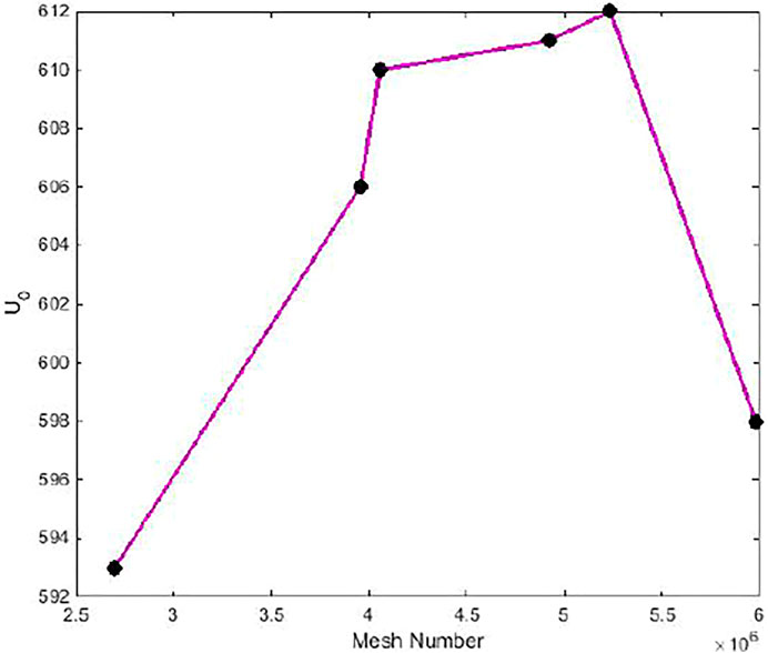
To examine the precision of the represented numerical approach, a heat exchanger with helical case studies is adopted. The first step in heat transfer study of a represented heat exchanger is tubes modeling of the exchanger using computation fluid mechanic technique. The existing experimental results for the proposed case study which was extracted for a simple helical exchanger can be considered as the numerical results validation. The exchanger has one turn and consists of two copper horizontal pipes that are placed in the same center. The outer surface diameter of the outer pipe and its thicknesses are 0.0159 and 0.008 m, respectively. The diameter of the inner pipe is 0.0095 m which has 0.008 m thickness. Also, the pitch dimension and the curvature of the heat exchanger
The governing equation of the fluid mechanic and heat transfer in a Cartesian coordinate system for constant density and viscosity of the fluid which is water can be represented as follows:
Here,
where
where
Here
where
The comparison result between the numerical calculation and what is represented by Rennie and Raghavan (2005) for the two helical heat exchangers is illustrated in the following Figure 3.
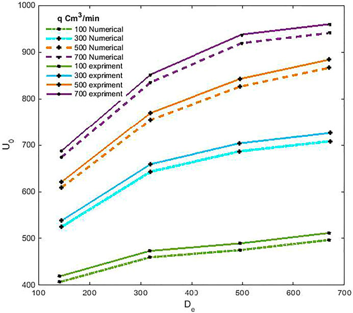
FIGURE 3. The comparison between the numerical and experimental results for heat transfer coefficient.
As can be calculated, the maximum differences between the numerical and experimental are nearly about 7% and prove the accuracy of the modeling.
Fluid Characteristics V.s Helical Heat Exchanger With Fins
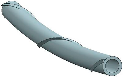
In this section, the effect of the fins (Turbulator) configurations (Figure 4) and dimensions on heat transfer and pressure loss of the above helical heat exchanger is investigated. Firstly, three types of fins are selected. The fins have triangular, rectangular, and compound (mix fin) shapes which are located on the top of the inner tube in a spiral form with an above-represented pitch angle. The current for the exchanger is parallel, and for all three different geometries of the fin, the mass flow is the same as those used for a simple two-pipe exchanger (without fin). Indeed, the mass flows are selected in such a way that value of the minimum difference exists between the experimental and numerical results. The comparison proves that the mass flow 300
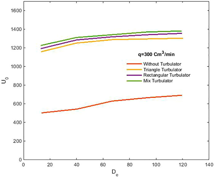
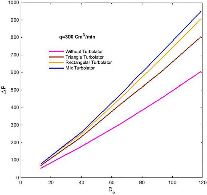
The fins are added in order that the effective surfaces have equal levels in terms of heat transfer performances. This means that the levels of heat transfer are considered equal for three types of the Turbolator. The dimensions of Torbulator are 0.001, 0.001 × 0.002 for equilateral triangle and rectangular fins, respectively. The extracted pressure loss and heat transfer coefficient of the helical pipe with the above fins are represented in the following figures (Figures 5, 6).
As shown in Figure 5, there is a remarkable increase in heat transfer coefficient for helical heat exchanger with fin (Turbolator) compared to the simple heat exchanger. Among the represented Turbolator, the rectangular and mix fins have more influence on heat transfer coefficient than the triangular Turbolator. The pressure loss between two pipe annulus areas for the helical heat exchanger is illustrated in Figure 6.
The study on pressure losses for different geometries shows a different behavior compared to heat transfer coefficient. As depicted in Figure 6, pressure loss has less value for equilateral triangle geometry than the rectangular and compound or mix geometries in a similar
where
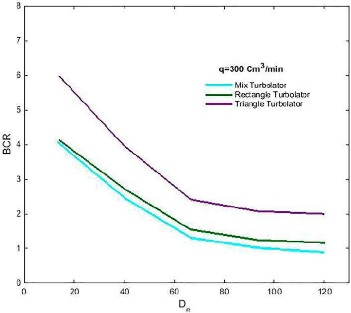
Based on extracted results illustrated in Figure 7, the equilateral triangle has more values of BCR for a specific pressure loss and shows better performances than the others. Furthermore, the BCR performance calculation proves that the rectangular configuration is preferable to the mix configuration.
Optimization Based on Fluid Performance Criteria
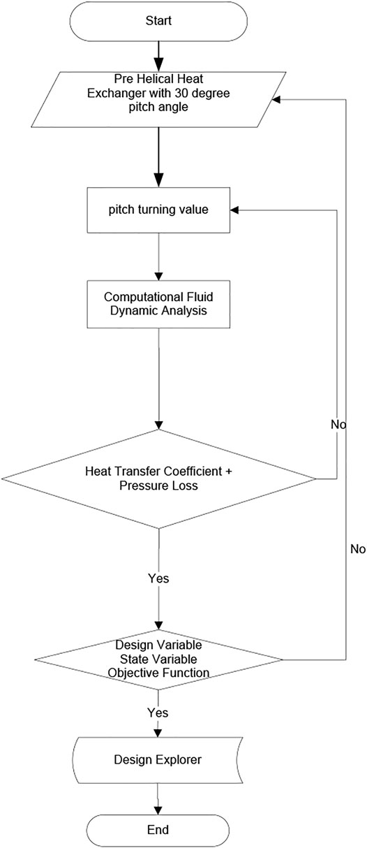
The represented multi-disciplinary design optimization (MDO) method is taken to propose the best performance of the mentioned helical heat exchanger for the equilateral triangular Turbolator. Genetic Algorithm (GA) and Artificial Neural Network (ANN) (Chen et al., 2020a; Chen et al., 2020b) are adopted to propose the best pitch turn of the above represented equilateral Turbolator. This design flow is constructed based on the parametrization of the pitch turning value, optimization algorithm, and a surrogate model on CFD results. Design of experiments (DOE) is also employed to create a sufficient database using the main mentioned heat exchanger along with Neural Network Algorithm. Based on the created database, the pressure loss and heat transfer coefficient criteria of the heat exchanger are evaluated. The pitch turning value is proposed using numerical calculation. The library is created based on the ANN results and converged to what is extracted in computational fluid dynamics. Finally, using the target goal satisfaction with results comparison procedure, the objective function is investigated. Indeed, the procedure is followed to minimize the pressure loss and increase the heat transfer coefficient using the following objective function:
where
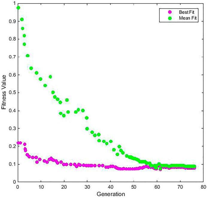
The Latin Hypercube type of 80 DOE experiments is applied and the validation procedure is conducted by 40% data and the remaining taken as network trainer. In the current training procedure of the ANN algorithm, the values of efficiency precision and deviation are 99.9 and 0.09%, respectively. The results of the three-dimensional CFD calculation and the values estimated with the network are compared in each cycle of genetic algorithm execution to evaluate the accuracy of the network. The network is re-trained if the three-dimensional CFD error is more than 0.3% and then results are added to the database. If the precision of the results is less than 0.3%, the CFD is ignored and just a neural network is employed for following the optimization procedure. Using 78 generations and 156 members in each generation, the process of optimization is conducted. As illustrated in Figure 9, fitness value has started at nearly 1 and reached to the value of less than 0.08. The estimated results are compared with the main composite wing characteristics to reach the best pitch turning the value of the pitch values. The result of the best value is obtained after seven iterations and is presented in Table 1.
The effect of the pitch angle and the best values of it based on the heat transfer coefficient and pressure loss for the represented helical heat exchanger is evaluated and depicted in Figures 10, 11. As can be seen, the amount of the pitch turns for three modes prove that the 23-degree pitch turn shows the best performance for the helical heat exchanger.
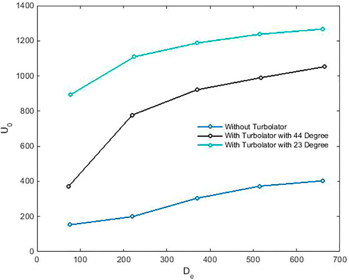
FIGURE 10. The comparison between the heat exchanger without Turbolator and heat exchangers with optimized and specific turn of Turbolator.
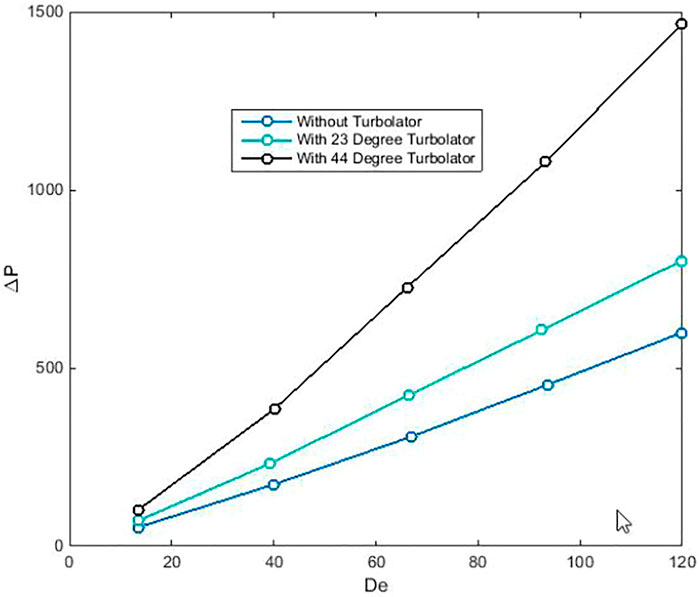
FIGURE 11. The comparison between pressure loss value of the heat exchanger without Turbolator and heat exchangers with optimized and specific turn of Turbolator.
From Figure 10, the heat exchanger with Turbolator has different values of heat transfer coefficient than the heat exchanger without Turbolator. Moreover, the comparison of the heat transfer coefficient between the heat exchangers with Turbolator and without Turbolator shows fewer difference values for a low De number. In other words, the evaluations for low De number reveal nearly 450% differences between the heat transfer coefficients of the heat exchanger with the presented optimized turn of Turbolator and the heat exchanger without the Turbolator.
However, the addition of the pitch turn of the Turbolator can increase the amount of heat transfer coefficient compared to the simple heat exchanger, and the study in Figure 11 discloses that the 23° turn of Turbolator demonstrates the minimum value for pressure loss. The investigation in Figure 11 proved that in low De number, the pressure loss has a minimum value in comparison to high De number values. The results also physically declared that increasing the pitch value can tend to blockage of the flow and decrease the percentage of the helical heat exchanger with Turbolator performances compared to the simple helical heat exchanger.
Conclusion
The optimization procedure of the helical heat exchanger was represented in this study. The effect of the mass flow rate on the helical heat exchanger performances were investigated and compared with what was extracted with experimental methodology. The result show good agreement and the maximum 7% differences between the numerical and experimental results were evaluated. Based on the minimum differences that occur between the mentioned numerical and experimental results, the flux value 300,300
Data Availability Statement
The original contributions presented in the study are included in the article/Supplementary Material, and further inquiries can be directed to the corresponding authors.
Author Contributions
WX and ZX collaborated in writing the manuscript and the representation of the Idea. IM and MS helped in the extraction of the result and the development of the optimization code. Also, MG and MA employed the optimization method on the model and feedback to the other authors.
Funding
This work was partially supported by Universiti Sains Malaysia under Short-term grant No. 304/PELECT/6315330.
Conflict of Interest
The authors declare that the research was conducted in the absence of any commercial or financial relationships that could be construed as a potential conflict of interest.
Publisher’s Note
All claims expressed in this article are solely those of the authors and do not necessarily represent those of their affiliated organizations, or those of the publisher, the editors, and the reviewers. Any product that may be evaluated in this article, or claim that may be made by its manufacturer, is not guaranteed or endorsed by the publisher.
Acknowledgments
We would like to thank Hassan Haddadpour, Milad Babapour Saatlou, and Zahra Sadat Afsharzad for their contribution to the extraction of the results and the development of the optimizations code.
References
Aryanfar, Y. (2020). A Review on the Water Sector in Iran: Current Forecasts, Scenario and Sustainability Issues. Int. J. Prog. Sci. Technol. 22, 13–18. doi:10.1002/suco.201900362
Assad, M. E. H., Aryanfar, Y., Radman, S., Yousef, B., and Pakatchian, M. (2021). Energy and Exergy Analyses of Single Flash Geothermal Power Plant at Optimum Separator Temperature. Int. J. Low Carbon Technol. 16, 873–881. doi:10.1093/ijlct/ctab014
Bhanvase, B. A., Sayankar, S. D., Kapre, A., Fule, P. J., and Sonawane, S. H. (2018). Experimental Investigation on Intensified Convective Heat Transfer Coefficient of Water Based PANI Nanofluid in Vertical Helical Coiled Heat Exchanger. Appl. Therm. Eng. 128, 134–140. doi:10.1016/j.applthermaleng.2017.09.009
Che, S., Breitenmoser, D., Infimovskiy, Y. Y., Manera, A., and Petrov, V. (2021). CFD Simulation of Two-phase Flows in Helical Coils. Front. Energ. Res. 8, 1–16. doi:10.3389/fenrg.2020.00065
Chen, S. B., Saleem, S., Alghamdi, M. N., Nisar, K. S., Arsalanloo, A., Issakhov, A., et al. (2021). Combined Effect of Using Porous Media and Nano-Particle on Melting Performance of PCM Filled Enclosure with Triangular Double Fins. Case Stud. Therm. Eng. 25, 100939. doi:10.1016/j.csite.2021.100939
Chen, S.-B., Beigi, A., Yousefpour, A., Rajaee, F., Jahanshahi, H., Bekiros, S., et al. (2020a). Recurrent Neural Network-Based Robust Nonsingular Sliding Mode Control with Input Saturation for a Non-holonomic Spherical Robot. IEEE access 8, 188441–188453. doi:10.1109/access.2020.3030775
Chen, S.-B., Soradi-Zeid, S., Jahanshahi, H., Alcaraz, R., Gómez-Aguilar, J. F., Bekiros, S., et al. (2020b). Optimal Control of Time-Delay Fractional Equations via a Joint Application of Radial Basis Functions and Collocation Method. Entropy 22, 1213. doi:10.3390/e22111213
Chu, H.-H., Zhao, T.-H., and Chu, Y.-M. (2020). Sharp Bounds for the Toader Mean of Order 3 in Terms of Arithmetic, Quadratic and Contraharmonic Means. Math. Slovaca 70, 1097–1112. doi:10.1515/ms-2017-0417
Chu, Y.-M., Nazir, U., Sohail, M., Selim, M. M., and Lee, J.-R. (2021). Enhancement in Thermal Energy and Solute Particles Using Hybrid Nanoparticles by Engaging Activation Energy and Chemical Reaction Over a Parabolic Surface via Finite Element Approach. Fractal Fract 5, 119. doi:10.3390/fractalfract5030119
Dean, W. R. (1928). LXXII.The Stream-Line Motion of Fluid in a Curved Pipe (Second Paper). Lond. Edinb. Dublin Philos. Mag. J. Sci. 5, 673–695. doi:10.1080/14786440408564513
Dean, W. R. (1927). XVI.Note on the Motion of Fluid in a Curved Pipe. Lond. Edinb. Dublin Philos. Mag. J. Sci. 4, 208–223. doi:10.1080/14786440708564324
El Haj Assad, M., Aryanfar, Y., Javaherian, A., Khosravi, A., Aghaei, K., Hosseinzadeh, S., et al. (2021). Energy, Exergy, Economic and Exergoenvironmental Analyses of Transcritical CO2 Cycle Powered by Single Flash Geothermal Power Plant. Int. J. Low-carbon Technol. 16, 1504–1518. doi:10.1093/ijlct/ctab076
El Maakoul, A., Laknizi, A., Saadeddine, S., El Metoui, M., Zaite, A., Meziane, M., et al. (2016). Numerical Comparison of Shell-Side Performance for Shell and Tube Heat Exchangers with Trefoil-Hole, Helical and Segmental Baffles. Appl. Therm. Eng. 109, 175–185. doi:10.1016/j.applthermaleng.2016.08.067
Ghalandari, M., Chau, K.-W., Ziamolki, A., Mosavi, A., Shamshirband, S., and Bornassi, S. (2019). Aeromechanical Optimization of First Row Compressor Test Stand Blades Using a Hybrid Machine Learning Model of Genetic Algorithm, Artificial Neural Networks and Design of Experiments. Eng. Appl. Comput. Fluid Mech. 13, 892–904. doi:10.1080/19942060.2019.1649196
Ghalandari, M., Maleki, A., Haghighi, A., Safdari Shadloo, M., Alhuyi Nazari, M., and Tlili, I. (2020). Applications of Nanofluids Containing Carbon Nanotubes in Solar Energy Systems: A Review. J. Mol. Liquids 313, 113476. doi:10.1016/j.molliq.2020.113476
Ghorbani Mianroudi, N., Gorji, M., and Taherian, H. (2008). “Experimental Study of Mixed Convection Shell-And-Coil Heat Exchanger,” in Heat Transfer Summer Conference Vol. 48487, 129–135. doi:10.1115/ht2008-56504
Han, J. T., Lin, C. X., and Ebadian, M. A. (2005). Condensation Heat Transfer and Pressure Drop Characteristics of R-134a in an Annular Helical Pipe. Int. Commun. Heat Mass Transfer 32, 1307–1316. doi:10.1016/j.icheatmasstransfer.2005.07.009
Irandoost Shahrestani, M., Maleki, A., Safdari Shadloo, M., and Tlili, I. (2020). Numerical Investigation of Forced Convective Heat Transfer and Performance Evaluation Criterion of Al2O3/water Nanofluid Flow Inside an Axisymmetric Microchannel. Symmetry 12, 120. doi:10.3390/sym12010120
Irandoost Shahrestani, M., Houshfar, E., Ashjaee, M., and Allahvirdizadeh, P. (2021). Convective Heat Transfer and Pumping Power Analysis of MWCNT+ Fe3O4/water Hybrid Nanofluid in a Helical Coiled Heat Exchanger with Orthogonal Rib Turbulators. Front. Energ. Res. 9, 12. doi:10.3389/fenrg.2021.630805
Jayakumar, J. S., Mahajani, S. M., Mandal, J. C., Iyer, K. N., and Vijayan, P. K. (2010). Thermal Hydraulic Characteristics of Air-Water Two-phase Flows in Helical Pipes. Chem. Eng. Res. Des. 88, 501–512. doi:10.1016/j.cherd.2009.09.007
Kumar, V., Saini, S., Sharma, M., and Nigam, K. D. P. (2006). Pressure Drop and Heat Transfer Study in Tube-In-Tube Helical Heat Exchanger. Chem. Eng. Sci. 61, 4403–4416. doi:10.1016/j.ces.2006.01.039
Mahajani, S. M., Mandal, J. C., Bhoi, R., Jayakumar, J. S., and Vijayan, P. K. (2008). Experimental and CFD Estimation of Heat Transfer in Helically Coiled Heat Exchangers. Chem. Eng. Res. Des. Trans. Inst. Chem. Eng. Part. A. 86, 221–232. doi:10.1016/j.cherd.2007.10.021
Mahariq, I., and Erciyas, A. (2017). A Spectral Element Method for the Solution of Magnetostatic fields. Turk J. Elec Eng. Comp. Sci. 25, 2922–2932. doi:10.3906/elk-1605-6
Mahariq, I., Kavyanpoor, M., Ghalandari, M., Nazari, M. A., and Bui, D. T. (2020). Identification of Nonlinear Model for Rotary High Aspect Ratio Flexible Blade Using Free Vibration Response. Alexandria Eng. J. 59, 2131–2139. doi:10.1016/j.aej.2020.01.029
Majid Etghani, M., and Amir Hosseini Baboli, S. (2017). Numerical Investigation and Optimization of Heat Transfer and Exergy Loss in Shell and Helical Tube Heat Exchanger. Appl. Therm. Eng. 121, 294–301. doi:10.1016/j.applthermaleng.2017.04.074
Maleki, A., Elahi, M., Assad, M. E. H., Nazari, M. A., Shadloo, M. S., and Nabipour, N. (2020). Thermal Conductivity Modeling of Nanofluids with ZnO Particles by Using Approaches Based on Artificial Neural Network and MARS. J. Therm. Anal. Calorim. 143, 1–12. doi:10.1007/s10973-020-09373-9
Naik, B. A. K., and Vinod, A. V. (2018). Heat Transfer Enhancement Using Non-newtonian Nanofluids in a Shell and Helical Coil Heat Exchanger. Exp. Therm. Fluid Sci. 90, 132–142. doi:10.1016/j.expthermflusci.2017.09.013
Panahi, D., and Zamzamian, K. (2017). Heat Transfer Enhancement of Shell-And-Coiled Tube Heat Exchanger Utilizing Helical Wire Turbulator. Appl. Therm. Eng. 115, 607–615. doi:10.1016/j.applthermaleng.2016.12.128
Pishkariahmadabad, M., Ayed, H., Xia, W.-F., Aryanfar, Y., Almutlaq, A. M., and Bouallegue, B. (2021). Thermo-economic Analysis of Working Fluids for a Ground Source Heat Pump for Domestic Uses. Case Stud. Therm. Eng. 27, 101330. doi:10.1016/j.csite.2021.101330
Prabhanjan, D. G., Raghavan, G. S. V., and Rennie, T. J. (2002). Comparison of Heat Transfer Rates Between a Straight Tube Heat Exchanger and a Helically Coiled Heat Exchanger. Int. Commun. Heat Mass Transfer 29, 185–191. doi:10.1016/s0735-1933(02)00309-3
Prabhanjan, D. G., Rennie, T. J., and Vijaya Raghavan, G. S. (2004). Natural Convection Heat Transfer from Helical Coiled Tubes. Int. J. Therm. Sci. 43, 359–365. doi:10.1016/j.ijthermalsci.2003.08.005
Ramezanizadeh, M., Alhuyi Nazari, M., Ahmadi, M. H., and Chau, K.-w. (2019). Experimental and Numerical Analysis of a Nanofluidic Thermosyphon Heat Exchanger. Eng. Appl. Comput. Fluid Mech. 13, 40–47. doi:10.1080/19942060.2018.1518272
Rennie, T. J., and Raghavan, V. G. S. (2005). Experimental Studies of a Double-Pipe Helical Heat Exchanger. Exp. Therm. Fluid Sci. 29, 919–924. doi:10.1016/j.expthermflusci.2005.02.001
Shadloo, M. S., Oger, G., and Le Touzé, D. (2016). Smoothed Particle Hydrodynamics Method for Fluid Flows, Towards Industrial Applications: Motivations, Current State, and Challenges. Comput. Fluids 136, 11–34. doi:10.1016/j.compfluid.2016.05.029
Shafee, A., Jafaryar, M., Abohamzeh, E., Nam, N. D., and Tlili, I. (2020). Simulation of Thermal Behavior of Hybrid Nanomaterial in a Tube Improved with Turbulator. J. Therm. Anal. Calorim. 143, 1–11. doi:10.1007/s10973-019-09247-9
She, L., and Fan, G. (2018). Numerical Simulation of Flow and Heat Transfer Characteristics of CuO-Water Nanofluids in a Flat Tube. Front. Energ. Res. 6, 57. doi:10.3389/fenrg.2018.00057
Sheeba, A., Abhijith, C. M., and Jose Prakash, M. (2019). Experimental and Numerical Investigations on the Heat Transfer and Flow Characteristics of a Helical Coil Heat Exchanger. Int. J. Refrigeration 99, 490–497. doi:10.1016/j.ijrefrig.2018.12.002
Song, Y.-Q., Hassan, M., Khan, S. U., Khan, M. I., Qayyum, S., Chu, Y.-M., et al. (2021a). Thermal and Boundary Layer Flow Analysis for MWCNT-SiO2 Hybrid Nanoparticles: An Experimental thermal Model. Mod. Phys. Lett. B 35, 2150303. doi:10.1142/s0217984921503036
Song, Y.-Q., Imran, M., Ali Khan, S., Waqas, H., Ullah Khan, S., Ijaz Khan, M., et al. (2021b). Applications of Modified Darcy Law and Nonlinear Thermal Radiation in Bioconvection Flow of Micropolar Nanofluid over an off Centered Rotating Disk. Alexandria Eng. J. 60, 4607–4618. doi:10.1016/j.aej.2021.03.053
Song, Y.-Q., Waqas, H., Al-Khaled, K., Farooq, U., Ullah Khan, S., Ijaz Khan, M., et al. (2021c). Bioconvection Analysis for Sutterby Nanofluid over an Axially Stretched Cylinder with Melting Heat Transfer and Variable Thermal Features: A Marangoni and Solutal Model. Alexandria Eng. J. 60, 4663–4675. doi:10.1016/j.aej.2021.03.056
Song, Y.-Q., Zhao, T.-H., Chu, Y.-M., and Zhang, X.-H. (2015). Optimal Evaluation of a Toader-type Mean by Power Mean. J. Inequalities Appl. 2015, 1–12. doi:10.1186/s13660-015-0927-6
Verma, P. D. S., and Ram, P. (1993). On the Low-Reynolds Number Magnetic Fluid Flow in a Helical Pipe. Int. J. Eng. Sci. 31, 229–239. doi:10.1016/0020-7225(93)90036-t
Webster, D. R., and Humphrey, J. A. C. (1997). Traveling Wave Instability in Helical Coil Flow. Phys. Fluids 9, 407–418. doi:10.1063/1.869139
Xiong, P.-Y., Almarashi, A., Dhahad, H. A., Alawee, W. H., Issakhov, A., and Chu, Y.-M. (2021). Nanoparticles for Phase Change Process of Water Utilizing FEM. J. Mol. Liquids 334, 116096. doi:10.1016/j.molliq.2021.116096
Zhao, T.-H., He, Z.-Y., He, Z.-Y., and Chu, Y.-M. (2020a). On Some Refinements for Inequalities Involving Zero-Balanced Hypergeometric Function. AIMS Math. 5, 6479–6495. doi:10.3934/math.2020418
Zhao, T.-H., Shi, L., and Chu, Y.-M. (2020b). Convexity and Concavity of the Modified Bessel Functions of the First Kind with Respect to Hölder Means. Rev. La Real Acad. Ciencias Exactas, Físicas y Nat. Ser. A. Matemáticas 114, 1–14. doi:10.1007/s13398-020-00825-3
Zhao, T.-H., Wang, M.-K., Wang, M.-K., and Chu, Y.-M. (2020c). A Sharp Double Inequality Involving Generalized Complete Elliptic Integral of the First Kind. AIMS Math. 5, 4512–4528. doi:10.3934/math.2020290
Zhao, T.-H., He, Z.-Y., and Chu, Y.-M. (2021a). Sharp Bounds for the Weighted Hölder Mean of the Zero-Balanced Generalized Complete Elliptic Integrals. Comput. Methods Funct. Theor. 21, 413–426. doi:10.1007/s40315-020-00352-7
Zhao, T.-H., Wang, M.-K., and Chu, Y. (2021b). Concavity and Bounds Involving Generalized Elliptic Integral of the First Kind. J. Math. Inequal. 15, 701–724. doi:10.7153/jmi-2021-15-50
Zhao, T.-H., Wang, M.-K., and Chu, Y.-M. (2021c). Monotonicity and Convexity Involving Generalized Elliptic Integral of the First Kind. Rev. La Real Acad. Ciencias Exactas, Físicas y Nat. Ser. A. Matemáticas 115, 1–13. doi:10.1007/s13398-020-00992-3
Keywords: helical heat exchanger, fins effects, heat transfer, pressure loss, multi-disciplinary design optimization method
Citation: Xifeng W, Xiaoluan Z, Mahariq I, Salem M, Ghalandari M, Ghadak F and Abedini M (2022) Performance Optimization of the Helical Heat Exchanger With Turbulator. Front. Energy Res. 9:789316. doi: 10.3389/fenrg.2021.789316
Received: 04 October 2021; Accepted: 30 December 2021;
Published: 15 February 2022.
Edited by:
Sorour Alotaibi, Kuwait University, KuwaitReviewed by:
Muhammad Ahmad Jamil, Northumbria University, United KingdomYashar Aryanfar, Universidad Autónoma de Ciudad Juárez, Mexico
Copyright © 2022 Xifeng, Xiaoluan, Mahariq, Salem, Ghalandari, Ghadak and Abedini. This is an open-access article distributed under the terms of the Creative Commons Attribution License (CC BY). The use, distribution or reproduction in other forums is permitted, provided the original author(s) and the copyright owner(s) are credited and that the original publication in this journal is cited, in accordance with accepted academic practice. No use, distribution or reproduction is permitted which does not comply with these terms.
*Correspondence: Zhang Xiaoluan, ZXZhbGl1MTEyOEBnbWFpbC5jb20=; Mohamed Salem, c2FsZW1tQHVzbS5teQ==
 Wang Xifeng1
 Ibrahim Mahariq
 Mohamed Salem
 Mohammad Ghalandari
 Mostafa Abedini
