 Fengbo Wen
 Yuxi Luo1
94% of researchers rate our articles as excellent or good
Learn more about the work of our research integrity team to safeguard the quality of each article we publish.
Find out more
ORIGINAL RESEARCH article
Front. Energy Res., 17 November 2021
Sec. Advanced Clean Fuel Technologies
Volume 9 - 2021 | https://doi.org/10.3389/fenrg.2021.789246
This article is part of the Research TopicAdvanced Technologies in Flow Dynamics and Combustion in Propulsion and PowerView all 25 articles
This study was carried out to investigate the loss mechanism of a blade with a harbor seal whisker structure on the trailing edge under different Mach numbers. The loss of high-pressure turbine blades with four different trailing edge geometries, including a prototype, an elliptical trailing edge (ETE), a sinusoidal trailing edge (STE), and a biomimetic trailing edge (BTE) at Mach numbers of 0.38–1.21 is studied. The delayed detached-eddy simulation method is used to predict the detailed flow of the four cascades. The result shows that, when the Mach number is less than 0.9, the BTE can effectively reduce the energy loss coefficient compared with the other three cases. As the Mach number increases, the three-dimensional characteristics of the wake behind the BTE weaken. The energy loss coefficient of the blade with the BTE is close to that of the blade with the ETE and STE when the Mach number is greater than 0.9. Besides this, by controlling the wake, the BTE can effectively suppress the dynamic movement of shock waves in the cascade at high Mach numbers.
Due to the wide application of modern gas turbines, such as power generation, aviation, and in the oil and gas industries, gas turbines are designed to meet different working conditions. As a type of continuous working equipment, the loss reduction of the gas turbine can save energy, and the blade profile optimization is an efficient way to reduce energy loss (Hamakhan and Korakianitis, 2010; Korakianitis et al., 2012; Zhang et al., 2012). For the gas turbine, the blade profile loss consists of boundary layer loss, shock loss, and trailing edge loss due to the mixing processes (Denton, 1993), and trailing edge loss accounts for one third of the total loss in subsonic flow (Mee et al., 1990). The unsteady motion of the vortex shedding from the trailing edge contributes significantly to the wake mixing loss (Lin et al., 2017a), acoustic resonances, and structural vibrations.
The flow of the turbine trailing edge is considered to be a steady process for a long time. With the introduction of flow visualizations, the consistent structure of the turbine trailing edge flow, known as the von Karman vortex street, has been revealed (Sieverding and Manna, 2020). Han and Cox (Han and Cox, 1982) use the kerosene smoke to visualize the three-dimensional structure of the vortices shedding from the turbine trailing edge. The holographic interferometric density measurement technique was adopted by Sieverding et al. (2003) to show the vortices shedding from a high-pressure turbine vane. The base pressure of the trailing edge is measured with pneumatic pressure taps and fast-response sensors. The results reveal the connection between the formation length of the trailing edge vortices and the base pressure coefficient. In the aspect of numerical simulation, various numerical methods are used to study the wakes of turbine blades. Léonard et al. (2010) compare the ability of Reynolds-averaged Navier–Stokes (RANS), unsteady RANS (URANS), and large eddy simulation (LES) methods to simulate a turbine blade at a high subsonic outlet Mach number. They show that the RANS method cannot depict the unsteady flow of the wake. Although the URANS method can predict the mean trailing edge wake to a certain extent, only the LES method can provide a detailed view of the wake. As a hybrid method, the delayed-detached eddy simulation (DDES) method can accurately predict the wake flow while reducing the computational cost in the boundary layer. Lin et al. (2017b) use a DDES code with a low-dissipation numerical scheme to simulate the flow of a high-pressure turbine stage. They explain the length characteristics of the wake vortices and reveal the transportation of the vortices.
The vortex shedding from the turbine trailing edge causes a high shear rate in the wake, which leads to high entropy generation in the wake. Therefore, controlling the shedding of vortices is an effective way to reduce wake loss. Denton and Xu (Denton and Xu, 1990) find that the base pressure of the trailing edge is closely related to vortices shedding and trailing edge loss, and increasing the base pressure can effectively reduce the loss in the wake. Motallebi and Norbury (Motallebi and Norbury, 1981) experimentally study the effects of base bleed on vortex shedding and base pressure of the blunt trailing edge. Their results show that a small amount of bleed air can shift the motion of the vortices and result in a substantial increase in base pressure. Furthermore, a larger amount of bleed air makes the vortices’ motion disappear. Raffel and Kost (Raffel and Kost, 1998) study the coolant ejection of the turbine trailing edge at Ma from 1.01 to 1.45. The results show that the coolant can change the shock system and modify the vortex shedding frequency. Bernardini et al. (2013) study the effect of trailing edge pulsating coolant ejection under supersonic flow. They conclude that the change in the value of the coolant, not the absolute value, affects the shape of the vortex. However, Xu and Denton (Xu and Denton, 1988) point out that, although the introduction of coolant ejection can increase the base pressure, additional losses are introduced by the coolant ejection. On the other hand, elliptic trailing is found to be able to delay the separation of the boundary layer and reduce the loss caused by vortex shedding (El-Gendi et al., 2013). El-Gendi et al. (2010) use the equidistant microtubes that connect the suction side and pressure side at the beginning of the trailing edge to control the wake. They find that the microtubes can reduce the blade profile loss by 3%. Wang et al. (2019) study the effect of the degree of suction-side convexity on the vortex shedding. Through the local spatial-temporal stability analyses, they find that the wake velocity profiles in the near-wake region are more unstable for a fuller suction boundary layer. Besides this, a more convex curvature can suppress the vortex shedding, and the trailing edge loss was lower. Inspired by the whisker of the harbor seal, the authors propose a bionic method to control the vortex shedding at the trailing edge of turbine blades (Luo et al., 2019).
Blind seals and seals living in turbid waters can track their prey by sensing the wakes left by their prey (Dehnhardt et al., 2001; Schulte-Pelkum et al., 2007; Wieskotten et al., 2010). The unique whisker structure of the seal gives the seal the ability to sense the wake. Ginter et al. (2012) provide a detailed description of a harbor seal’s whisker structure. Beem and Triantafyllou (2015) experimentally study the vibration of the harbor seal’s whisker model under uniform flow and upstream wake. Their results reveal that the whisker of the harbor seals hardly vibrates under uniform flow. While under the upstream wake, the whisker behaves as unique vibrations. Hanke et al. (2010) use experimental and numerical methods to study the wake of a harbor seal’s whisker under uniform flow. They indicate that the structure of the harbor seal’s whiskers can break the coherence structure of Karman vortices and reduce the vortex-induced vibrations. In the authors’ previous research (Luo et al., 2019), the method of using the harbor seal structure to construct a bionic blade trailing edge is proposed. It is proved by DDES numerical simulation that the biomimetic trailing edge (BTE) suppresses the formation of a Karman vortex at the trailing edge when the isentropic exit Mach number is 0.79 and generates small spanwise vortices, which reduces the wake loss.
Actually, at different exit Mach numbers, the patterns of trailing edge vortex shedding are very different. Carscallen et al. (1996) use the ultrashort Schlieren photographs to investigate the wake of a transonic turbine vane at various Ma. They find that the shedding of the von Karman vortex street was intermittent when Ma < 0.7 and continuous when 0.7 < Ma < 1.0. When Ma > 1.0, the von Karman vortex street was found to be transient between different shedding patterns. Melzer and Pullan (Melzer, Pullan) study the influence of different blade trailing edge geometries on loss at exit Ma from 0.4 to 0.97. Their experimental results show that the suppression of vortex shedding under transonic conditions can effectively reduce loss. Graham and Kost (Graham and Kost, 1979) measure the loss of two high-turning turbine blades at the outlet Ma from 0.7 to 1.4. Their results show that the loss first increases, then decreases, and then increases with the outlet Ma. Sieverding et al. (1978) measure the performance of various suction-side curvatures of the turbine blade. Their results also show that there is a peak and a valley in the area where the outlet Ma is close to 1.
Although it is proved that the bionic trailing edge can suppress the Karman vortex and reduce wake loss significantly at an exit Mach number of 0.79 in (Luo et al., 2019), as mentioned above, different exit Mach numbers have a great influence on the form of trailing edge vortex for conventional blades, so the important purpose of this paper is to study the influence of the BTE on the wake vortex and the ability to control wake loss under different Mach number conditions (0.38–1.21), especially after the Mach number is greater than 1, and the influence of BTE on the shockwave system and related loss. This study provides an important reference for the application of BTE in turbines under different working conditions.
Four turbine blades with different trailing edge geometries are studied in this paper. The prototype blade is a high-pressure turbine guide vane, called VKI CT96 (Sieverding et al., 2003) as shown in Figure 1A. The detailed parameters of the VKI CT96 cascade are listed in Table 1. The biomimetic blade is designed based on the VKI CT96 profile. Because the biomimetic blade contains the characteristics of ellipse and sine, the profiles with the elliptical trailing edge (ETE) and sinusoidal trailing edge (STE) are also studied in this research as shown in Figures 1B,C.
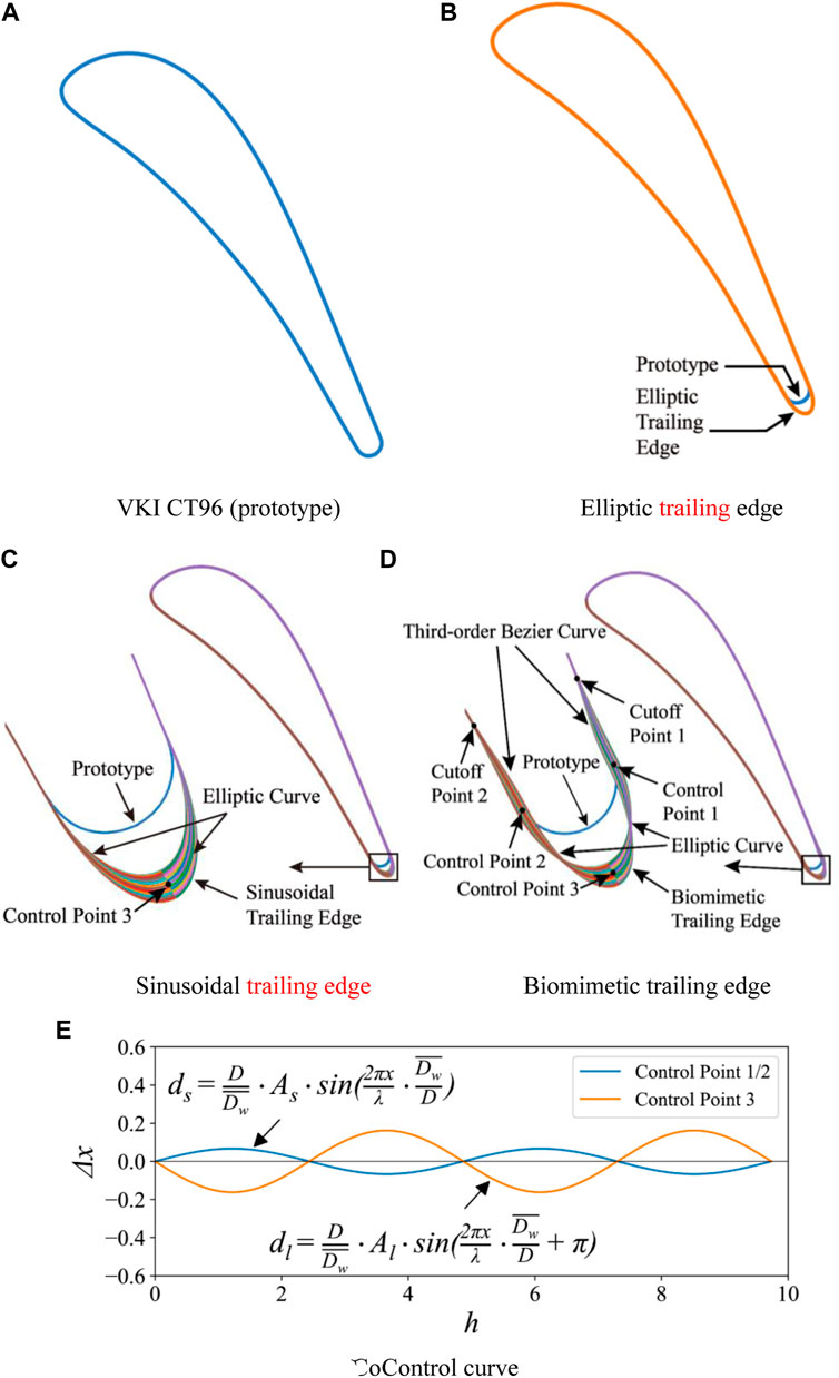
FIGURE 1. The profiles of the four cases and the generation method of the biomimetic blade. (A) VKI CT96 (prototype) (B) Elliptic trailing edge. (C) Sinusoidal trailing edge (D) Biomimetic trailing edge. (E) Control curve.
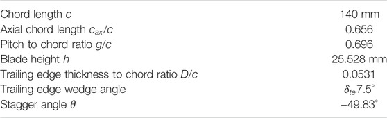
TABLE 1. VKI CT96 cascade characteristics (Sieverding et al., 2003).
The seal whisker parameters provided by Hanke et al. (2010) are used to generate the biomimetic blade. There are two main features of the whisker: The first is that the cross-section of the beard is elliptical, and the second is that both the major and minor axes of the cross-section ellipse varies sinusoidally along the spanwise direction; the average ratio of major and minor axes is 2:1. Therefore, the ellipse with a 2:1 major and minor axis ratio is selected as the base trailing edge to generate the three-dimensional BTE. The profile of the biomimetic blade is shown in Figure 1D. To maintain the thickness of the blade trailing edge, the chord length of the biomimetic blade is slightly extended to achieve the first feature. Besides this, two minor axis endpoints (control points 1 and 2) and one major axis endpoint (control point 3) were selected to change sinusoidally in the spanwise direction. The sine curve corresponding to the three control points is shown in Figure 1E. The sine curve expression at control points 1 and 2 is
where
where
The part of the trailing edge is separated from cutoff points 1 and 2, and the blade profile before the cutoff points is unchanged. The third-order Bezier curve is used to connect cutoff points 1 and 2 with control points 1 and 2. Besides this, the elliptical curve is used to connect control points 1 and 2 with control point 3. The biomimetic blade is formed by stacking the profile lines of each layer in the spanwise direction. For the sinusoidal blade, only control point 3 changes sinusoidally in the spanwise direction. The three-dimensional view of the four cascades is shown in Figure 2.
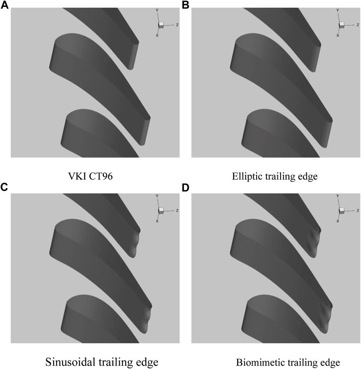
FIGURE 2. The three-dimensional view of the four cascades. (A) VKI CT96 (B) Elliptic trailing edge. (C) Sinusoidal trailing edge (D) Biomimetic trailing edge.
The computational domain is shown in Figure 3. The inlet is at one axial chord length upstream of the blade leading edge. The outlet is at one axial chord length downstream of the blade trailing edge. The height of the computational domain is 0.278 times the axial chord length, which is one period of the biomimetic blade. A total of 5.17 million cells are used to discretize this computational domain and the mesh in the region of the leading edge, trailing edge, and the wake are refined as shown in Figure 4.
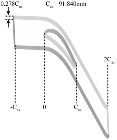
FIGURE 3. The computational domain.
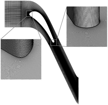
FIGURE 4. Computational mesh and details at the leading and trailing edges.
The boundary conditions used in the current simulation are consistent with the experiment of Sieverding et al. (2003) as shown in Table 2. The total temperature and total pressure are given at the inlet of the computational domain. The suction and pressure sides of the blade are set as adiabatic and nonslip walls. The pitchwise and spanwise boundaries of the computational domain are set to be periodic boundary conditions. To study the loss of the four blades under different Mach numbers, the outlet static pressure was adjusted to change the outlet Mach number.
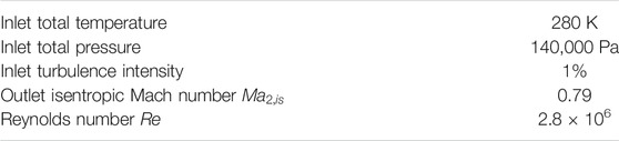
TABLE 2. The flow conditions in the experiment (Sieverding et al., 2003).
The commercial software ANSYS FLUENT is used as the solver in the current study. This software is based on the finite volume method. The DDES method is selected to simulate the turbulent flow and
The experimental data of Sieverding et al. (2003) is used to verify the validity of the numerical results. All verifications are based on experimental conditions with an outlet Mach number of 0.79. The comparison of experimental and numerical results of isentropic Mach number distribution on the blade surface is shown in Figure 5. The results of the DDES method are generally in good agreement with the experimental results. The numerical result at the leading edge has a lower isentropic Mach number, which may be due to the slight difference between the experimental air inlet angle and the numerical simulation.
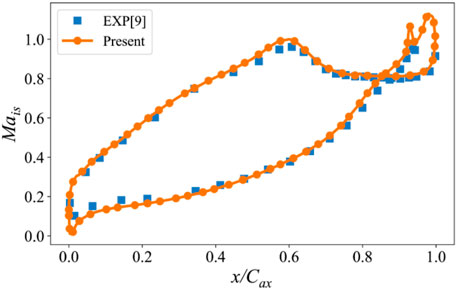
FIGURE 5. Time-averaged isentropic Mach number.
The comparison of the velocity profile of the boundary layer between the numerical and experimental results is shown in Figure 6. The boundary layer velocity profiles are measured at one trailing edge thickness upstream of the trailing edge circle. The velocity profile of the boundary layer on the pressure side is in good agreement with the experimental results. The boundary layer velocity profile on the suction side is consistent with the experimental results. The velocity profile in the middle of the boundary layer is slightly different from the experimental results. This may be because the URANS method in the boundary layer has insufficient ability to capture the turbulent flow on the suction side.
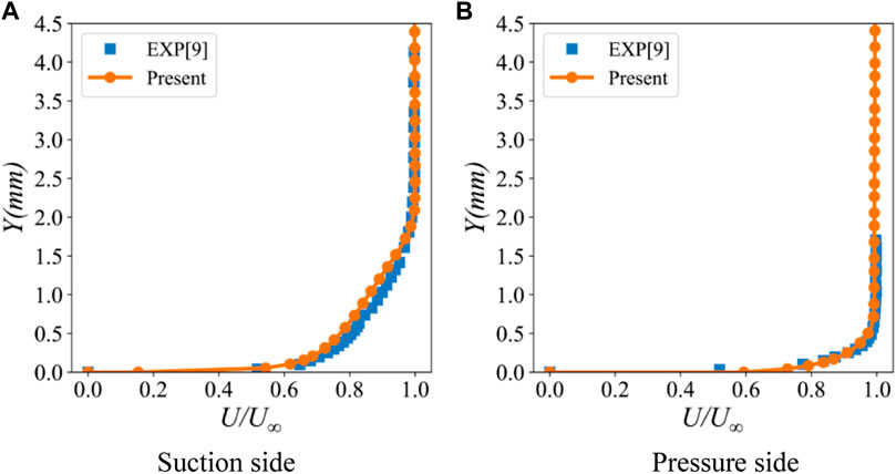
FIGURE 6. Velocity profiles in the boundary layer at one trailing edge thickness upstream of the trailing edge circle. (A) Suction side (B) Pressure side.
The comparison of the time-averaged pressure distribution at the trailing edge is shown in Figure 7. There are three local minimum values, respectively, on the suction side, pressure side, and center of the trailing edge. The trend obtained by the current numerical results is consistent with the experimental results, but the pressure distribution is underestimated. This may be due to the insufficient ability of the DDES method to predict near-wall regions with strong separation flows. Compared with the numerical results of El-Gendi et al. (2013), the results obtained by the current DDES method are more consistent with the experimental results. In a word, from the comparison of the numerical and experimental results, the current numerical method is reliable.

FIGURE 7. Time-averaged pressure distribution at the trailing edge.
The energy loss coefficient was used to evaluate the profile loss of the four blades at different Mach numbers. The energy loss coefficient is defined as
where
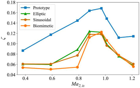
FIGURE 8. The relationship between the energy loss coefficient of the four blades and the outlet isentropic Mach number.
For the prototype blade, in the subsonic region, the energy loss coefficient increases with the increase of exit isentropic Mach number and reaches the maximum at the Mach number about 0.97 and then decreases until it reaches the minimum at the Mach number close to 1.1. After that, when the Mach number increases further, the energy loss coefficient increases slightly again, which may be caused by the increase of shockwave loss. The mechanism that the turbine vane has a local maximum in the transonic region is revealed by previous researchers. Before reaching the maximum, the loss is mainly caused by Karman vortex street. When the exit Mach number increases to about 0.97, the trailing shockwave system appears at the trailing edge, and then the origin of the vortex street migrates from the blade trailing edge to a point downstream of the junction of the two trailing edge shear layers (Carscallen et al., 1996). The trailing edge base pressure increases; the wake vortex narrows and becomes weaker. Therefore, although the shockwave brings a certain loss, the loss caused by Karman vortex street dominates and is greatly reduced, so the total loss shows a downward trend.
For the blades with ETE and STE, these two kinds of blades contain part of the characteristics of the harbor seal whisker. In the entire simulated Mach number range, the losses of these two blades are greatly reduced compared to the prototype. The losses of these two blades are close in most ranges except when the Mach number is in the range of 0.6–1.0. In this range, the loss of the blade with the STE is lower. Besides this, the Mach number corresponding to the local maximum of the loss is shifted forward compared with the prototype.
The blade with the BTE contains all the characteristics of the harbor seal whisker. The loss of the blade with the BTE in all simulated Mach numbers is greatly reduced compared with the prototype. When the Mach number is less than 0.9, the loss of the blade with the BTE is lower than the blades with the ETE and STE. The Mach number corresponding to the local maximum of the loss of the blade with the BTE is closer to the prototype.
To reveal the mechanism of the loss of the four profiles under different Mach numbers, the wake characteristics of these profiles at different outlet Mach numbers are analyzed in this section. The vortex characteristics in the wake are displayed using the Q criterion as shown in Figure 9. The wakes at the two typical exit Mach numbers are displayed, and they are
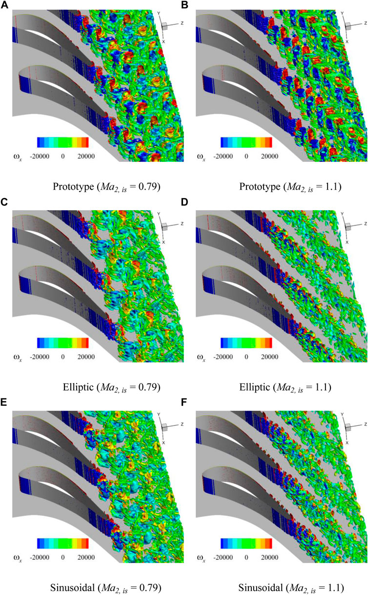
FIGURE 9. Isosurfaces of Q criterion
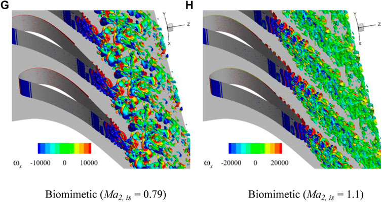
FIGURE 9. (Continued)
For
For
To reveal the controlability of the profile with all the characteristics of the whisker under different Mach numbers, we show the Q criterion isosurface under different Mach numbers as shown in Figure 10. For
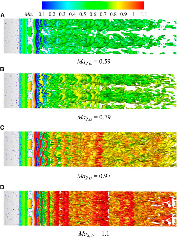
FIGURE 10. The Q-criterion
To study the flow mechanism of the BTE at different Mach numbers, the time-averaged surface streamlines in the trailing edge region under different Mach numbers as shown in Figure 11. For
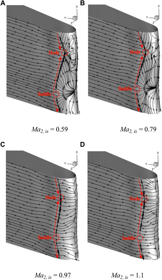
FIGURE 11. Time-averaged surface streamlines in the trailing edge region of different Mach numbers. (A)
Because the profile of BTE changes along the blade height, to better analyze the shock system and vortex structures on the sections at different spanwise positions, as shown in Figure 12, three sections of peak, middle and valley are taken for comparative analysis. In Figure 13, contours of density gradient on peak, middle, and valley sections at
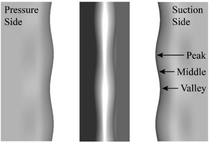
FIGURE 12. Sections of peak, middle, and valley.
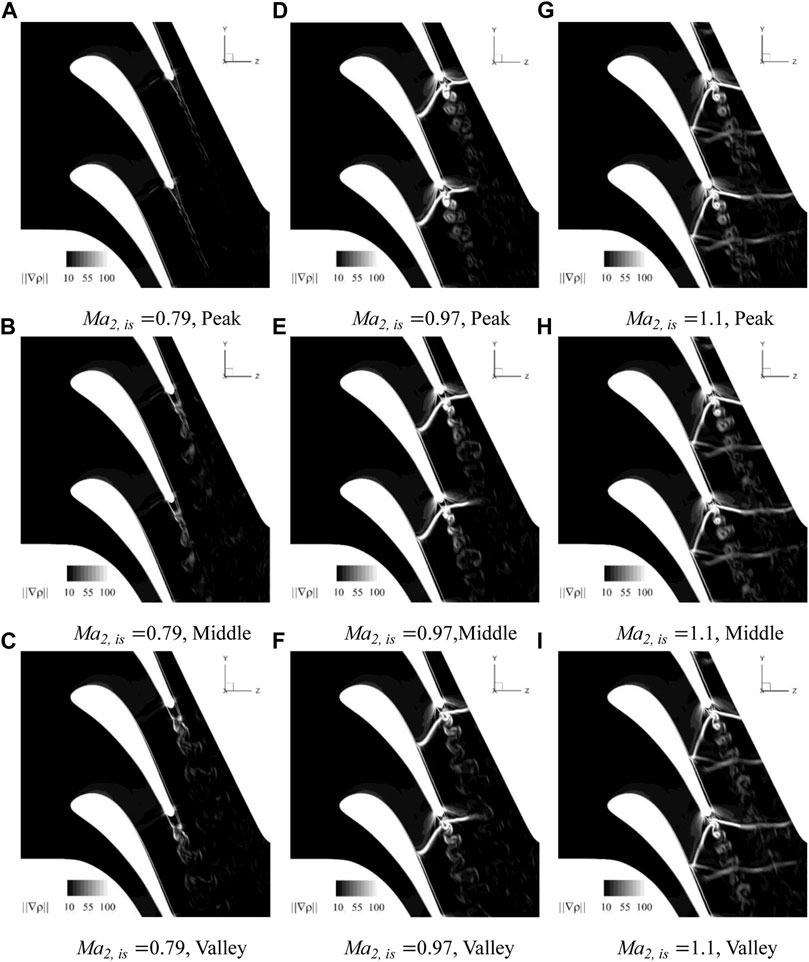
FIGURE 13. Numerical Schlieren on peak, middle and valley sections at
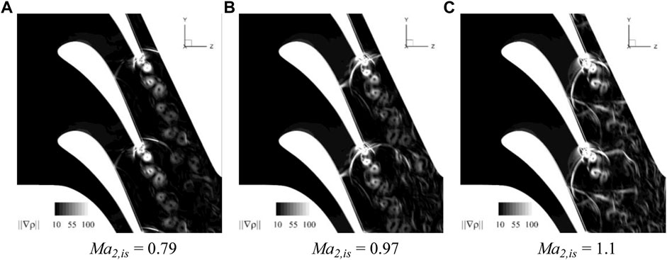
FIGURE 14. Numerical Schlieren at different Mach numbers for the prototype. (A) Ma2,is = 0.79 (B) Ma2,is = 0.97 (C) Ma2,is = 1.1.
It can be seen from Figures 13A–C that, when
At
When
From Figures 13G–I, it can be seen that, when
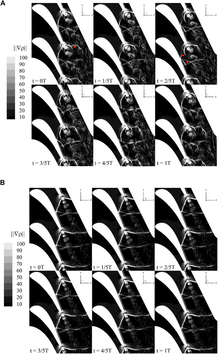
FIGURE 15. Numerical Schlieren of prototype and BTE at different times when Ma = 1.1. (A) Prototype (B) Biomimetic.
Figure 15 shows the numerical Schlieren at different times in a cycle when
The flow of the four blades, including prototype, ETE, STE, and BTE, are simulated at the exit isentropic Mach number of 0.38–1.21. The simulation results of the DDES method are generally in good agreement with the experimental data.
Within the Mach number range of 0.38–1.21, the energy loss coefficients of the four cases all show a trend of first increasing and then decreasing. In addition, the energy loss coefficients of the ETE, STE, and BTE are smaller than that of the prototype in the entire Mach number range. When the Mach number is less than 0.9, the BTE can effectively reduce the energy loss coefficient compared with the other three cases.
With the increase of Mach number, complex shockwave patterns appear in both the prototype and biomimetic cascade. When the exit Mach number approaches or exceeds 1, the trailing edge shock pattern of the BTE is more stable, and the wake vortex is relatively weak, which has little effect on the shockwaves. At
The original contributions presented in the study are included in the article/Supplementary Material, further inquiries can be directed to the corresponding author.
FW is the corresponding author of the article, and the main work includes calculation, analysis and article writing. YL’s main work includes numerical computation and post-processing. ShW’s main work includes numerical computation and post-processing. SoW assists in writing and reviewing the article. ZW reviewed the article and put forward some suggestions for revision.
The authors acknowledge financial support from the Natural Major Science and Technology Project of China (No. 2017-I-0005-0006) and the Outstanding Youth Science Foundation of Heilongjiang Province of China (No. YQ 2020E016).
Author SW is employed by The 705 Research Institute of China Shipbuilding Industry Corporation.
The remaining authors declare that the research was conducted in the absence of any commercial or financial relationships that could be construed as a potential conflict of interest.
All claims expressed in this article are solely those of the authors and do not necessarily represent those of their affiliated organizations, or those of the publisher, the editors and the reviewers. Any product that may be evaluated in this article, or claim that may be made by its manufacturer, is not guaranteed or endorsed by the publisher.
Beem, H. R., and Triantafyllou, M. S. (2015). Wake-induced 'slaloming' Response Explains Exquisite Sensitivity of Seal Whisker-like Sensors. J. Fluid Mech. 783, 306–322. doi:10.1017/jfm.2015.513
Bernardini, C., Salvadori, S., Martelli, F., Paniagua, G., and Saracoglu, B. H. (2013). Pulsating Coolant Ejection Effects Downstream of Supersonic Trailing Edge. Eng. Appl. Comput. Fluid Mech. 7 (2), 250–260. doi:10.1080/19942060.2013.11015468
Carscallen, W., Fleige, H., and Gostelow, J. (1996). Transonic Turbine Vane Wake Flows. in Turbo Expo: Power for Land, Sea, and Air. American Society of Mechanical Engineers (ASME), V001T01A109. doi:10.1115/96-gt-419
Dehnhardt, G., Mauck, B., Hanke, W., and Bleckmann, H. (2001). Hydrodynamic Trail-Following in Harbor Seals ( Phoca vitulina ). Science 293 (5527), 102–104. doi:10.1126/science.1060514
Denton, J. D. (1993). The 1993 Igti Scholar Lecture: Loss Mechanisms in Turbomachines. J. Turbomach. 115 (4), 621–656. doi:10.1115/1.2929299
Denton, J. D., and Xu, L. (1990). The Trailing Edge Loss of Transonic Turbine Blades. J. Turbomach. 112, 277–285. doi:10.1115/1.2927648
El-Gendi, M. M., Ibrahim, M. K., Mori, K., and Nakamura, Y. (2010). Novel Flow Control Method for Vortex Shedding of Turbine Blade. Trans. Jpn. Soc. Aero. S Sci. 53 (180), 122–129. doi:10.2322/tjsass.53.122
El-Gendi, M. M., Lee, S. W., Joh, C. Y., Lee, G. S., Son, C. H., and Chung, W. J. (2013). Elliptic Trailing Edge for a Turbine Blade: Aerodynamic and Aerothermal Effects. Trans. Jpn. Soc. Aero. S Sci. 56 (2), 82–89. doi:10.2322/tjsass.56.82
Ginter, C. C., DeWitt, T. J., Fish, F. E., and Marshall, C. D. (2012). Fused Traditional and Geometric Morphometrics Demonstrate Pinniped Whisker Diversity. PloS one 7 (4), e34481. doi:10.1371/journal.pone.0034481
Graham, C., and Kost, F. (1979). Shock Boundary Layer Interaction on High Turning Transonic Turbine Cascades. American Society of Mechanical Engineers (ASME).
Hamakhan, I. A., and Korakianitis, T. (2010). Aerodynamic Performance Effects of Leading-Edge Geometry in Gas-Turbine Blades. Appl. Energ. 87 (5), 1591–1601. doi:10.1016/j.apenergy.2009.09.017
Han, L. S., and Cox, W. (1982). A Visual Study of Turbine Blade Pressure-Side Boundary Layers, In Turbo Expo: Power for Land, Sea, and Air. American Society of Mechanical Engineers (ASME), V001T01A020. doi:10.1115/82-gt-47
Hanke, W., Witte, M., Miersch, L., Brede, M., Oeffner, J., Michael, M., et al. (2010). Harbor Seal Vibrissa Morphology Suppresses Vortex-Induced Vibrations. J. Exp. Biol. 213 (15), 2665–2672. doi:10.1242/jeb.043216
Korakianitis, T., Hamakhan, I. A., Rezaienia, M. A., Wheeler, A. P. S., Avital, E. J., and Williams, J. J. R. (2012). Design of High-Efficiency Turbomachinery Blades for Energy Conversion Devices with the Three-Dimensional Prescribed Surface Curvature Distribution Blade Design (circle) Method. Appl. Energ. 89 (1), 215–227. doi:10.1016/j.apenergy.2011.07.004
Lakshminarayana, B. (1996). Fluid Dynamics and Heat Transfer of Turbomachinery. New York: John Wiley & Sons, 567–570.
Léonard, T., Gicquel, L. Y., Gourdain, N., and Duchaine, F. (2010). Steady/unsteady Reynolds-averaged Navier–Stokes and Large Eddy Simulations of a Turbine Blade at High Subsonic Outlet Mach Number. J. Turbomach. 137 (4).
Lin, D., Su, X., and Yuan, X. (2017). Ddes Analysis of the Wake Vortex Related Unsteadiness and Losses in the Environment of a High-Pressure Turbine Stage. J. Turbomach. 140 (4).
Lin, D., Yuan, X., and Su, X. (2017). Local Entropy Generation in Compressible Flow through a High Pressure Turbine with Delayed Detached Eddy Simulation. Entropy 19 (1), 29. doi:10.3390/e19010029
Luo, Y., Wen, F., Wang, S., Zhang, S., Wang, S., and Wang, Z. (2019). Numerical Investigation on the Biomimetic Trailing Edge of a High-Subsonic Turbine Blade. Aerospace Sci. Tech. 89, 230–241. doi:10.1016/j.ast.2019.04.002
Mee, D., Baines, N., Oldfield, M., and Dickens, T. (1990). An Examination of the Contributions to Loss on a Transonic Turbine Blade in cascade. In Turbo Expo: Power for Land, Sea, and Air. American Society of Mechanical Engineers, V005T16A012. doi:10.1115/90-gt-264
Melzer, A., and Pullan, G. The Role of Vortex Shedding in the Trailing Edge Loss of Transonic Turbine Blades. J. Turbomach. 141 (4).
Motallebi, F., and Norbury, J. F. (1981). The Effect of Base Bleed on Vortex Shedding and Base Pressure in Compressible Flow. J. Fluid Mech. 110, 273–292. doi:10.1017/s0022112081000748
Raffel, M., and Kost, F. (1998). Investigation of Aerodynamic Effects of Coolant Ejection at the Trailing Edge of a Turbine Blade Model by Piv and Pressure Measure-Ments. Experiments in Fluids 24 (5-6), 447–461. doi:10.1007/s003480050194
Schulte-Pelkum, N., Wieskotten, S., Hanke, W., Dehnhardt, G., and Mauck, B. (2007). Tracking of Biogenic Hydrodynamic Trails in Harbour Seals (phoca Vitulina). J. Exp. Biol. 210 (5), 781–787. doi:10.1242/jeb.02708
Sieverding, C., Decuypere, R., and Hautot, P. (1978). Investigation of Transonic Steam Turbine Tip Sections with Various Suction Side Blade Curvatures. STIN 80, 26632.
Sieverding, C. H., Richard, H., and Desse, J.-M. (2003). Turbine Blade Trailing Edge Flow Characteristics at High Subsonic Outlet Mach Number. J. Turbomach. 125 (2), 298–309. doi:10.1115/1.1539057
Sieverding, C., and Manna, M. (2020). A Review on Turbine Trailing Edge Flow. Ijtpp 5 (2), 10. doi:10.3390/ijtpp5020010
Wang, S., Wen, F., Zhang, S., Zhang, S., and Zhou, X. (2019). Influences of Trailing Boundary Layer Velocity Profiles on Wake Vortex Formation in a High-Subsonic-Turbine cascade. Proc. Inst. Mech. Eng. A: J. Power Energ. 233 (2), 186–198. doi:10.1177/0957650918779935
Wieskotten, S., Dehnhardt, G., Mauck, B., Miersch, L., and Hanke, W. (2010). Hydrodynamic Determination of the Moving Direction of an Artificial Fin by a Harbour Seal (phoca Vitulina). J. Exp. Biol. 213 (13), 2194–2200. doi:10.1242/jeb.041699
Xu, L., and Denton, J. D. (1988). The Base Pressure and Loss of a Family of Four Turbine Blades. J. Turbomach. 110 (1), 9–17. doi:10.1115/1.3262174
Zhang, W., Zou, Z., and Ye, J. (2012). Leading-edge Redesign of a Turbomachinery Blade and its Effect on Aerodynamic Performance. Appl. Energ. 93, 655–667. doi:10.1016/j.apenergy.2011.12.091
ETE = elliptic trailing edge
STE = sinusoidal trailing edge
BTE = biomimetic trailing edge
Keywords: biomimetic trailing edge, turbine blade, Mach number, energy loss, shock wave
Citation: Wen F, Luo Y, Wang S, Wang S and Wang Z (2021) Numerical Study on the Biomimetic Trailing Edge of a Turbine Blade Under a Wide Range of Outlet Mach Numbers. Front. Energy Res. 9:789246. doi: 10.3389/fenrg.2021.789246
Received: 04 October 2021; Accepted: 19 October 2021;
Published: 17 November 2021.
Edited by:
Lipo Wang, Shanghai Jiao Tong University, ChinaReviewed by:
Xiaoqing Qiang, Shanghai Jiao Tong University, ChinaCopyright © 2021 Wen, Luo, Wang, Wang and Wang. This is an open-access article distributed under the terms of the Creative Commons Attribution License (CC BY). The use, distribution or reproduction in other forums is permitted, provided the original author(s) and the copyright owner(s) are credited and that the original publication in this journal is cited, in accordance with accepted academic practice. No use, distribution or reproduction is permitted which does not comply with these terms.
*Correspondence: Fengbo Wen, ZmVuZ2JvQGhpdC5lZHUuY24=
Disclaimer: All claims expressed in this article are solely those of the authors and do not necessarily represent those of their affiliated organizations, or those of the publisher, the editors and the reviewers. Any product that may be evaluated in this article or claim that may be made by its manufacturer is not guaranteed or endorsed by the publisher.
Research integrity at Frontiers
Learn more about the work of our research integrity team to safeguard the quality of each article we publish.