 Yuchen Hao
 Dawei Su
94% of researchers rate our articles as excellent or good
Learn more about the work of our research integrity team to safeguard the quality of each article we publish.
Find out more
ORIGINAL RESEARCH article
Front. Energy Res. , 11 November 2021
Sec. Process and Energy Systems Engineering
Volume 9 - 2021 | https://doi.org/10.3389/fenrg.2021.785420
This article is part of the Research Topic Advanced Technologies for Planning and Operation of Prosumer Energy Systems View all 111 articles
With the increased penetration of the photovoltaic (PV) energy, the power system stability problem becomes an issue, as the output power of PV plants has unpredictable fluctuations. To maintain the power stability of the PV plants, battery energy storages (BESs) play an important role due to their fast and accurate response speed. However, it is challenging that the BES with multiple sub-modules responds well to the PV power fluctuations resulting from the various influence factors, such as defects, faults, and partial shading. Therefore, a bi-level control strategy is proposed in this paper, aiming at minimizing the operation cost of BES in maintaining power stability. The control strategy consists of the PV power fluctuations identification block and the mitigation block. In specific, the identification block can output the power fluctuation of a PV system by the PV power fluctuation identification technique. The technique is developed based on the characteristics of PV-string current under electrical faults and partial shading conditions. Meanwhile, the mitigation block can manage the multiple battery sub-modules with different regulation characteristics to meet the power fluctuations. At last, the promising results are obtained by MATLAB\Simulink with the coordinated operation of those two blocks, including the precise condition of the PV system and the optimal power output of each battery sub-module. Therefore, a comprehensive bi-level control strategy is developed to regulate the operation of battery sub-modules for PV-BES systems.
To reduce the greenhouse gas emissions, replacing the fossil energy generation with renewable energies has become an inevitable trend in the modern power grid. Photovoltaic (PV) plants play an essential role in renewable energies and are regarded as one of the fastest-growing renewable energy systems of recent decades. As reported by the International Renewable Energy Agency (IRENA), the cumulative global PV installations exceeded 580 GW at the end of 2019 (IRENA, 2020). However, different from the conventional generators, the output power of PV plants is characterized by high intermittency and randomness. Meanwhile, the PV plants cannot provide the system inertia due to their lack of the rotation parts (Akshay and Abraham, 2019; Zhang et al., 2021). Therefore, how to strengthen the power regulation capability of PV plants has become a topic of concern recently.
At the beginning, the below maximum power point tracking (MPPT) controller operation schemes are introduced as in Tarraso et al. (2017); Sangwongwanich et al. (2017) and Liu et al. (2014) to enable a certain capacity of power reserve from the PV plants. For example, the master-slave control is adopted in Tarraso et al. (2017), in which the master PV arrays reserve power following the slave PV arrays operating at MPPT. Also, the control strategies in Sangwongwanich et al. (2017) and Liu et al. (2014) achieve the power reserve by enabling the PV arrays to reach MPPT periodically and estimating MPPT through power-voltage curve respectively. However, in those control strategies, a proportion of the captured solar energy has been wasted more or less, which leads to the reduced efficiency of PV plants.
To avoid the waste of the solar energy, battery energy storages (BESs) are combined with PV plants as PV-BES systems, as in Kumar and Singh, (2019); Gira and Dahiya, (2020); Narayanan et al. (2020). In detail, a PV-BES system is developed based on a learning-quantization current control strategy in Kumar and Singh, (2019), a multifunctional voltage source converter is used for PV-BES system in Gira and Dahiya, (2020), and a voltage regulation controller is adopted to regulate the DC link voltage to compensate reactive power in a PV-BES as shown in Narayanan et al. (2020). Also, BESs provide a power response as part of the virtual synchronous generators as in Hou et al. (2020). Technically speaking, BESs, especially hybrid BESs, have great advantages in responding PV power fluctuations as their fast response ability. However, the operation cost of BESs in those control strategies is generally ignored.
The operation cost of BESs in PV plants can be improved by well-designed control strategies from two perspectives. On one hand, the control strategy must precisely identify the influence factors of the PV power fluctuation, and the influence factors can be defects, faults, and partial shading. In detail, the defects such as diode failures, hot spots, cracks in cells, and delamination may lead to the permanent damage and energy reduction of a PV module (Munoz et al., 2011). The defects rarely happen, because the development of PV cell technology has extended the warranties of a PV module to more than 25 years. Also, the electrical faults, such as line-to-ground (LG) fault, line-to-line (LL) fault, and arc fault (Pillai et al., 2019) may cause the permanent damage and energy reduction of a PV system. Moreover, the partial shading is usually due to bird droppings, dust, fallen leaves, trees, and buildings. Thus, different from defects and faults, the power fluctuations of PV plants caused by the partial shading should be identified by the control strategy, and mitigated by BESs.
To identify the partial shading, it is necessary to monitor the operation condition and output power of the PV plants. The current-voltage (I-V) characteristics of PV modules are commonly used to analyze the condition of PV plants (Wang et al., 2016; Chen et al., 2018, 2019). However, I-V testers are required to acquire the I-V curves of PV arrays which will cause extra costs. Since the MPPT controller keeps tracking the maximum power point (MPP) to output maximum power, the operation points during the partial shading and electrical faults are the same. Thus, it is difficult to differentiate the partial shading and electrical fault based on the operation points from I-V curves. Methodologies based on statistical analysis can be applied to study the performance of PV plants (Garoudja et al., 2017; Jenitha and Immanuel Selvakumar, 2017; Harrou et al., 2018). Nevertheless, a large amount of data on irradiance and temperature is needed. The partial shading and LL faults can be classified by machine learning tools for condition monitoring of PV systems (Akram and Lotfifard, 2015; Harrou et al., 2019). But, it is mandatory to collect and emulate numerous operation conditions to acquire sufficient training data. The performance of PV systems can also be evaluated by Gaussian mixture models and empirical mode decomposition (Ding et al., 2019). Extra sensors can be designed and installed on each PV module to detect potential malfunctions (Guerriero et al., 2016). The digital twin approach is developed to estimate the condition of a distributed power electronic-based PV system (Jain et al., 2020). Therefore, a cost-effective and reliable control strategy to identify the partial shading of PV plants is still lacking.
On the other hand, the control strategy must precisely manage the hybrid BESs at the same time, as they have different regulation characteristics. With the developments of battery technologies, BESs consist of several sub-modules with different regulation characteristics become dominating in the near future (Zhang et al., 2016), to broaden the BESs’ regulation capability. For example, the BES in Zhangbei’s demonstration contains lithium battery sub-modules, sodium-sulfur sub-modules, and redox flow sub-modules. Thus, it is challenging to control battery sub-modules with different rated power, capacity, ramping rate, and real-time SoC in responding power fluctuations. In detail, sub-modules as in Lou et al. (2016) respond to the power fluctuations in proportion to their rated power, but the different ramping rates between the power type and energy type sub-modules are ignored. Also, power fluctuations are decomposed into the high component and the low component by Fourier transformation as in Bao et al. (2015); Hirase et al. (2016), and sub-modules take the corresponding component according to their ramping rate. Nevertheless, in those control strategies, SoC cannot be recovered until it crosses the upper/lower thresholds.
Control strategies including SoC recovery stage are further developed in Tan and Zhang (2017); Megel et al. (2018); Doenges et al. (2020). For example, an SoC recovery phase is arranged after each response of the power fluctuations, as in Doenges et al. (2020), and a state-machine-based control strategy is shown in Tan and Zhang, (2017). However, SoC crossing the upper/lower thresholds cannot be eliminated, due to the randomness of recovery stage. A BES regulation cost function is formulated in Megel et al. (2018), in which SoC is first regarded as one of the cost influence factors.
Up to now, none of the control strategies can minimize the BES operation cost from both PV power fluctuation identification and mitigation. Therefore, a bi-level control strategy for BES in PV-BES system is proposed in this paper, in which the operation cost of BES is minimized. The specific contributions of this paper are summarized as follows. 1) An identification block with PV power fluctuation identification technique is developed. It can output accurate power fluctuation since the characteristics of PV-string current under electrical faults and partial shading conditions are considered. 2) A PV power fluctuation mitigation technique is developed based on the regulation characteristics of BES including rated power, rated capacity, ramping rate and real-time SoC.
The rest of the paper is organized as follows. The framework of PV-BES system with the proposed control strategy is introduced in the next section. The details of the bi-level control strategy for PV-BES system including the power fluctuations identification block and the power fluctuations mitigation block are presented in the following section. At last, the performance of the control strategy and the conclusion of the paper are in the last two sections.
The equivalent model of the PV-BES system including the bi-level control strategy for BES are shown as Figure 1, consists of PV plants, BES with several sub-modules, and DC-DC converter. In specific, the PB-BES system is a hybrid system which shares the power from the PV system and BES through a DC link by using a bi-directional DC-DC converter. Furthermore, the bi-level control strategy consists of the PV power fluctuation identification block and the mitigation bock, and the process of the control strategy can be summaries as follows. In detail, the PV system is in normal operation and the BES is charging or discharging on schedule. The presence of partial shading and electrical faults affect the operation of the PV system leading to power fluctuations. In this case, PV power fluctuation identification block will check the causes of power fluctuations, and the warning information is displayed when an electrical fault happens. The instructions are sent to the mitigation block to regulate the operation of the BES system when the partial shading occurs. At last, the mitigation block further manages the output power of battery sub-modules according to their regulation characteristics.
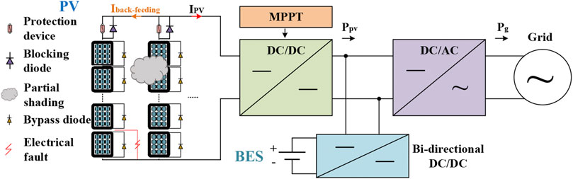
FIGURE 1. Framework of PV-BES system including the BES bi-level control strategy.
In this section, the models of PV plants and BES are introduced as follows. The PV module consists of series and parallel connected PV cells, which composes of a negative type (N-type) layer, a positive type (P-type) layer, and a PN junction. Due to the PV effect, a PV cell can absorb photon energy from sunlight to produce free-moving electrons to generate electricity. The PV module is developed based on a single-diode model. The PV array is connected to a MPPT controller and it keeps tracking the MPPs to output the maximum power from the PV plant. The perturb and observe method is adopted for the MPPT algorithm. As in Figure 2, an equivalent circuit of PV module of single-diode is depicted. The current output from a PV module is Ipv, the current generated by photon energy is Iph, and they can be expressed as 1) and 2) respectively. The model of PV module can be developed based on those equivalent circuit and equations.
Where the Io is the saturation current, Id is the diode current, Ish is the current passing shunt resistance, Isc is the short-circuit current, VPV is the output voltage, Rs is the series resistance, Rsh is the shunt resistance, n is the ideality factor of the diode, q is the electron charge, k is the Boltzmann constant, S is the solar irradiance in W/m2, Jo is the temperature coefficient of a PV cell, T is the cell temperature, Tref is the reference temperature of 298 K.
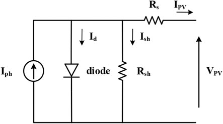
FIGURE 2. Equivalent circuit of a single-diode PV module.
Generally, the BES system adopts conventional lead-acid batteries since they are stable and low-cost. However, the lead-acid battery is limited in lifetime, requires a long charging time, is greatly affected by temperature, needs routine maintenance, and causes serious pollution. With the development of new-material batteries, the lithium-ion battery has the advantages of high energy density, fast charging, and long lifetime. Therefore, the lithium-ion battery is adopted to develop the BES system. The energy stored in the battery is limited and varies during charging and discharge period. Thus, it is important to determine the model parameters before modelling a battery. The capacity of a battery is affected by many factors. For example, the larger the discharge current, the smaller the battery discharge capacity. Besides, the discharge capacity is higher at high temperatures. During the charging and discharge period of a battery, the voltage of a battery varies with the capacity. When the capacity of battery decreases, the voltage will decrease. The remaining capacity of a battery can be described by the state of charge (SOC). The SOC can be expressed by 3, in which Qr is the remaining capacity, Q is the capacity of battery.
The typical battery discharge mode is constant current discharge under different currents. The characteristic curve is shown in Figure 3A, including the exponential region and the rated region. Specifically, the voltage is at the fully charged condition. The voltage decreases rapidly with the discharging of the battery. In the rated region, the voltage almost remains unchanged. After the rated region, the voltage decreases slowly to zero. The equivalent circuit of a battery is composed of a controlled voltage source (E) and a series-connected internal resistance (Rb) as shown in Figure 3B. In that figure, Vb and ib represent the terminal voltage and the current, respectively. It is supposed that the internal resistance is unchanged. Also, the mathematical model of battery can be expressed as (4), in which Eo is the voltage when the battery capacity is zero, K is the polarization voltage, A is the magnitude of exponential region, i1 is the low frequency current, B is reciprocal of time constant of rated region. At last, the BES system can be developed based on the mathematical model.
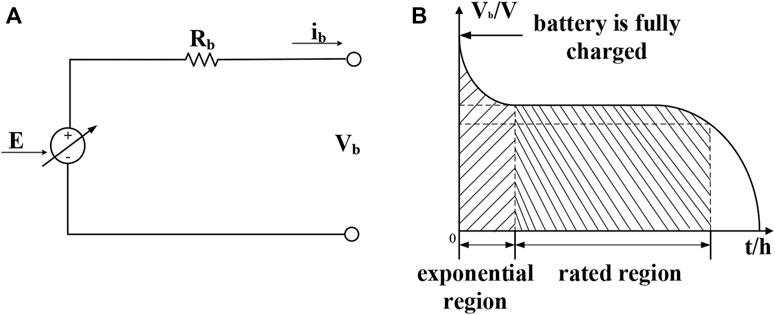
FIGURE 3. (A) Characteristic curve of battery in constant current discharge mode. (B) Equivalent circuit of battery.
The bi-level control strategy consists of the power fluctuations identification block and the power fluctuation mitigation block. Initially, a PV array in a row of three modules and a column of four modules is developed as Figure 4A. The PV module (CS3U-375MS-AG, Canadian Solar Inc) with a maximum power of 375 W is used. The I-V and P-V characteristics of the PV system at the irradiance of 600 W/m2 and temperature of 25°C is shown in Figure 4B. The PV system can produce a maximum power of 2.68 kW at the MPP of 158.40 V and 16.93A. The MPPs move to (159.60 V, 14.16 A) and (124.20 V, 16.94 A) when one of the PV modules is in partial shading with an irradiance of 300 and 100 W/m2 respectively. For a four-module string, the LG faults when 25%, 50%, and 75% of the PV modules in a PV string are evaluated as shown in Figure 4A. The 25% means that one PV module of four series-connected PV modules is under faulty conditions. The I-V and P-V curves are shown in Figure 4C. The MPP of 25% LG fault is (124.80 V, 16.97 A). The MPPs of 25 and 50% LG fault are the same at (158.40 V, 11.29 A). In this case, the potential LL faults can be caused by 25% or 50% of modules between two strings are misconnected as shown in Figure 4A. The MPPs of 25 and 50% LL faults are (124.80 V, 16.98 A) and (160.80 V, 11.34 A) as depicted in Figure 4D.
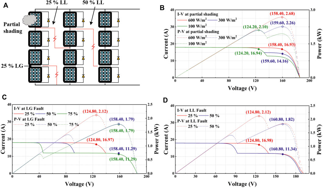
FIGURE 4. (A) Potential LG and LL faults in a PV array. (B) I-V and P-V curves of the PV system when a PV module is in partial shading. (C) I-V and P-V curves of the PV system when one of the strings is under 25, 50, and 75% LG fault condition. (D) I-V and P-V curves of the PV system when 25 and 50% LL faults occur between two strings.
According to those practical results, the MPP varies with partial shading and electrical faults conditions. However, there are cases in which the MPP is the same at partial shading and electrical faults. Since the defects rarely happen, they are not considered in this paper. For instance, the PV system operates at almost the same MPP under the condition of partial shading of 100 W/m2, 25% LG fault, and 25% LL fault. The MPPs of 50 and 75% LG faults are approximately the same as the 50% LL fault. Therefore, it is difficult to detect and differentiate the partial shading and electrical faults in a PV-BES system, which is also a main challenge to the identification block.
To develop the identification block, the string current under the various conditions is evaluated to design the condition monitoring algorithm and current sensing scheme, based on the investigated performance of the PV system in conditions of normal operation, partial shading, and electrical fault. A reliable and convenient condition monitoring technique is developed for the identification block, investigating the effects of the MPPT controller on electrical faults and partial shading.
In specific, the string current of PV array is analyzed to derive the mathematical model for condition monitoring of PV system. The LG fault and LL faults are studied to derive the equation of the string current. Only single LG faults and LL faults are considered since multiple LG faults and LL faults will cause apparent faulty current or short-circuit current. Thus, the operation condition and MPPs are different from partial shading. When an LG fault occurs within a PV string, there are two potential working conditions. The case one is that the faulty string still works with voltage higher than the voltage at the MPP (Vmp) and current lower than the current at the MPP (Imp). The unfaulty strings work with a voltage lower than Vmp to ensure that the PV array is operating at a point nearby the MPP to generate the maximum power. Another case is that the faulty string is open circuit since it cannot meet the operation voltage of unfaulty string. The unfaulty string works at MPP. This is due to the MPPT controller keeps tracking the MPP to ensure that the PV array generates the maximum power. Therefore, equations can be derived to estimate the percentage of PV modules of the faulty string (P) to sustain the operation. For instance, the PV array in structure of row (x) × column (y). Eq. 5 can be used to represent this case, in which Iuf is the current of the unfaulty string, y* is the number of the unfaulty string. In this case, the y* is y-1. Hence, Eq. 6 is established.
Furthermore, when LL fault occurs, suppose a number of m modules in the beginning part of the first string (S1) and a number of n modules in the beginning part of the second string (S2) are misconnected. The voltage of the beginning part of S1 equals to the voltage of the beginning part of S2. Since the MPPT controller keeps tracking the MPP, the voltage of unfaulty strings is slightly lower than Vmp. Besides, the voltage of unfaulty string is almost same as Vmp. Thus, Eq. 7 can be derived to estimate the condition of PV array, in which Isc is the short circuit current, Voc is the open circuit voltage.
According to the characteristics of PV string current, the algorithm can be developed based on the 5) and 7) to monitoring the LG faults and LL faults as depicted in Figure 5. The Hall-effect current sensors can be installed on the beginning and terminal of PV strings to measure the current of each PV string. Other non-invasive magnetic sensors such as magnetoresistance sensors can also be used and the price is typically lower than 1 USD. The current of the beginning of PV string (IS1a, IS2a, … ISya) and terminal of PV string (IS1b, IS2b, … ISyb) can be measured to detect LG and LL faults. The power fluctuation identification block is developed on the basis of the algorithm. The algorithm is relatively simple compared to other condition monitoring algorithms and the computational cost is low. The power identification block alarms the system when LG and LL faults are detected. The instructions are sent to power fluctuation mitigation blocks when partial shading is detected. The innovation is that it can identify partial shading and electrical faults when the MPPs are the same in these two cases.
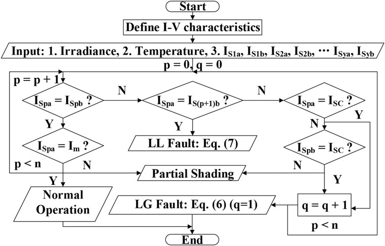
FIGURE 5. Condition monitoring algorithm for LG faults and LL faults.
Once the part of power fluctuations of PV has been decided to be responded by the BES, the power fluctuation mitigation block can further manage the battery sub-modules with different regulation characteristics. To minimize the operation cost and to maintain the SoC level of each battery sub-module, the operation cost function is defined as (8). In specific, the different coefficients of the cost function can distinguish the model differences in response to the power fluctuations. Furthermore, SoCn,t can be can be written as a function of BES charging and discharging power in (9). And, Eq. 8 can be deduced as (10).
Where, Jn,t represents cost function of the nth battery sub-module at t intercal; Pn,tc and Pn,td represents the charging and discharging power of the nth battery sub-module respectively, and either Pn,tc or Pn,td is zero because the sub-module operates on the charging or the discharging mode; SoCn,t is the real-time SoC of the nth sub-module, and SoCn0 is a constant representing the reference value, around which SoCn,t varies; Sn represents the rated capacity of the nth sub-module; an and bn are positive constants, indicating that the degree of the influence from the output power and SoC on operation cost, and the value of an and bn are empirical value from the experimental data; ηc and ηd are the charging\discharging efficiency of the modules; αnc, αnd, βn,tc, βn,td, and γn,t variates.
The duty of the power fluctuation mitigation block is to distribute the power demand to each module. At the beginning, the objective of the mitigation block is to minimize the operation cost of the BES. Meanwhile, the power demand must be met, and each module must be constrained by their regulation characteristics including rated power, capacity, ramping rate, and SoC. Furthermore, the distribution can be achieved to solve an optimization problem. In detail, the objective function of the power fluctuation mitigation block is shown as (11), adding the operation cost of each sub-module together. The equality and inequality constraints are listed as (12)–(15). At last, the quadratic programming is applied to solve the optimization problem. Because the quadratic function is a convex function, and the minimum value exists.
To verify the feasibility of the bi-level control strategy, the simulation model of the PV-BES system is developed by MATLAB/Simulink based on the theory of PV-BES system explained above. In particular, The PV module (CS3U-375MS-AG, Canadian Solar Inc) with a maximum power of 375 W is used. Also, the BES consists of four battery sub-modules, and their regulation characteristics are shown in Table 1 including rater power, ramping rate, rated capacity, charging \discharging efficiency, response time, and cost function coefficients.
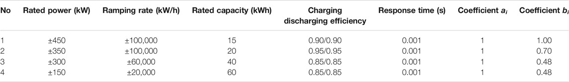
TABLE 1. Regulation characteristic of four battery sub-modules.
The weather conditions for 6 h are shown in Figures 6A,B, including the light irradiance and the environment temperature. The PV power fluctuations are shown in Figure 6C, which are total results from the shading. To mitigate the power fluctuations, two mitigation modes marked as Mode one and Mode two are achieved by the power mitigation block in Figure 6D and Figure 6E. In specific, the output power of PV keeps constant every 0.5 h in Mode 1, and the output power of PV is constant during the whole 6 h period.
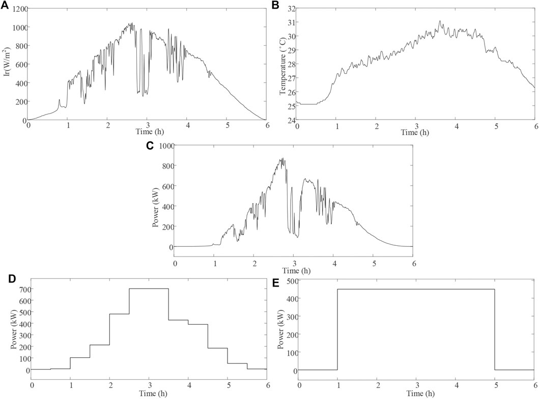
FIGURE 6. (A) Light irradiance curve. (B) Environment temperature curve. (C) PV output power fluctuation curve. (D) Mitigated PV output power in Mode 1. (E) Mitigated PV output power in Mode 2.
Furthermore, the output power of each battery sub-module in those two Modes are shown in Figures 7A,B, while the corresponding SoC are shown in Figures 7C,D. In detail, the regulation cost of each sub-module is positively related to its cost coefficient and SOC offset, and the output power of each energy storage is allocated according to the lowest total regulation cost, according to the operation of battery sub-modules in Mode 1. For example, the battery sub-modules #1 is sensitive to the decline of SOC as it has a large adjustment cost coefficient Bi. Meanwhile, the battery sub-modules #1 makes full use of its advantages, as long as the step increase or drop of power fluctuations happen.
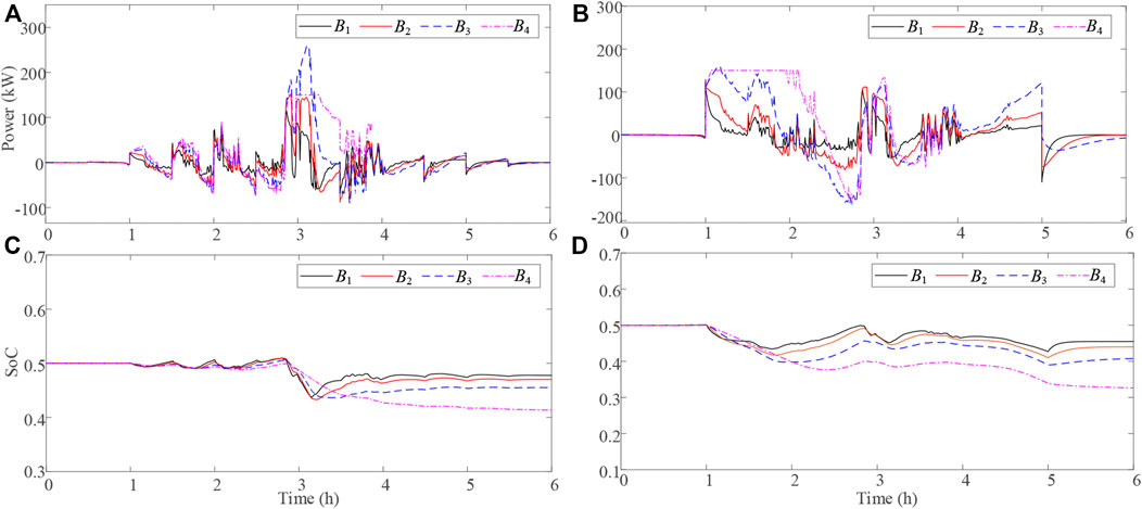
FIGURE 7. (A) Output power of each battery sub-modules in Mode 1. (B) Output power of each battery sub-modules in Mode 2. (C) SoC of each battery sub-modules in Mode 1. (D) SoC of each battery sub-modules in Mode 2.
Moreover, the SOC of battery sub-module #4 varies in a relatively larger range, as it is with a low regulation cost coefficient Bi. The output power decreases to ensure the SOC balancing until 4 h later, as its regulation cost increases significantly in Mode 1. Similarly, the battery sub-module #4 takes the most mitigation responsibility in the first 2 h in Mode 2, as it is with the low regulation cost coefficient Bi. Its output power decreases with the increase of SOC offset.
At last, the proposed control strategy was compared with another two strategies, marked as Strategy #2 and Strategy #3, which are defined in Table 2, together with the regulation cost accumulated for 6 h. The BES in Mode 1 has a lower cost than it has in Mode 2. Meanwhile, The proposed bi-level control strategy meets the mitigation of PV power with the lowest regulation cost in both operation modes. In addition, the proposed control strategy can achieve the SoC balancing without the signal tracking error.
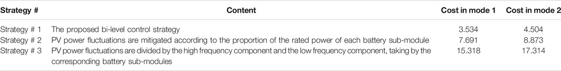
TABLE 2. Frequency response performance of Area #2 under different REP levels.
In this paper, a bi-level control strategy is developed to minimize the operational cost of BES for power stability of a PV-BES system. It consists of PV power-fluctuations identification block and mitigation block. The identification block is capable of identifying the electrical faults and partial shading conditions of a PV system based on the string-current characteristics. The information of power fluctuation of a PV system is outputted to the mitigation block to regulate the operation of battery sub-modules to meet the power fluctuations. The simulation results and case study results verified that bi-level control strategy can monitor the condition of the PV system and optimize the operation of each battery sub-modules. It will warn the system when an electrical fault occurs. The sub-battery modules operate only when the power fluctuations are caused by the partial shading. The results show that the BES can mitigate the fluctuations with the lowest regulation cost, according to their regulation characteristics. Thus, a competent bi-level control strategy is successfully developed to achieve the power stability of a PV-BES system in a reliable and low-cost manner.
The original contributions presented in the study are included in the article/supplementary material, further inquiries can be directed to the corresponding author.
YH proposed the concept of the project, and acted as the project administrator. DS designed the system model and established the details of control strategy. ZL analyzed the data and carried out the simulation. All authors approved the submitted version.
YH, DS and ZL were employed by Control Center of State Grid of Jiangsu Electric Power Co., Ltd.
All claims expressed in this article are solely those of the authors and do not necessarily represent those of their affiliated organizations, or those of the publisher, the editors and the reviewers. Any product that may be evaluated in this article, or claim that may be made by its manufacturer, is not guaranteed or endorsed by the publisher.
Akram, M. N., and Lotfifard, S. (2015). Modeling and Health Monitoring of DC Side of Photovoltaic Array. IEEE Trans. Sustain. Energ. 6, 1245–1253. doi:10.1109/TSTE.2015.2425791
Akshay, R. S. R., and Abraham, R. J. (2019). Load-frequency Regulation with Solar PV and Battery Energy Storage System. Int. J. Power Energ. Syst. 39, 10–16. doi:10.2316/J.2019.203-0084
Bao, Z., Zhou, Q., Yang, Z., Yang, Q., Xu, L., and Wu, T. (2015). A Multi Time-Scale and Multi Energy-type Coordinated Microgrid Scheduling Solution-Part I: Model and Methodology. IEEE Trans. Power Syst. 30, 2257–2266. doi:10.1109/TPWRS.2014.2367127
Chen, Z., Chen, Y., Wu, L., Cheng, S., and Lin, P. (2019). Deep Residual Network Based Fault Detection and Diagnosis of Photovoltaic Arrays Using Current-Voltage Curves and Ambient Conditions. Energ. Convers. Manag. 198, 111793. doi:10.1016/j.enconman.2019.111793
Chen, Z., Han, F., Wu, L., Yu, J., Cheng, S., Lin, P., et al. (2018). Random forest Based Intelligent Fault Diagnosis for PV Arrays Using Array Voltage and String Currents. Energ. Convers. Manag. 178, 250–264. doi:10.1016/j.enconman.2018.10.040
Ding, K., Feng, L., Zhang, J., Chen, X., Chen, F., and Li, Y. (2019). A Health Status-Based Performance Evaluation Method of Photovoltaic System. IEEE Access 7, 124055–124065. doi:10.1109/ACCESS.2019.2937546
Doenges, K., Egido, I., Sigrist, L., Lobato Miguelez, E., and Rouco, L. (2020). Improving AGC Performance in Power Systems with Regulation Response Accuracy Margins Using Battery Energy Storage System (BESS). IEEE Trans. Power Syst. 35, 2816–2825. doi:10.1109/TPWRS.2019.2960450
Garoudja, E., Harrou, F., Sun, Y., Kara, K., Chouder, A., and Silvestre, S. (2017). Statistical Fault Detection in Photovoltaic Systems. Solar Energy 150, 485–499. doi:10.1016/j.solener.2017.04.043
Gira, N., and Dahiya, A. K. (2020). Solar PV-BES in Distribution System with Novel Technique for DC Voltage Regulation. Eng. Sci. Technol. Int. J. 23, 1058–1067. doi:10.1016/j.jestch.2020.01.004
Guerriero, P., Di Napoli, F., Vallone, G., d'Alessandro, V., and Daliento, S. (2016). Monitoring and Diagnostics of PV Plants by a Wireless Self-Powered Sensor for Individual Panels. IEEE J. Photovoltaics 6, 286–294. doi:10.1109/JPHOTOV.2015.2484961
Harrou, F., Sun, Y., Taghezouit, B., Saidi, A., and Hamlati, M.-E. (2018). Reliable Fault Detection and Diagnosis of Photovoltaic Systems Based on Statistical Monitoring Approaches. Renew. Energ. 116, 22–37. doi:10.1016/j.renene.2017.09.048
Harrou, F., Taghezouit, B., and Sun, Y. (2019). Improved $k$NN-Based Monitoring Schemes for Detecting Faults in PV Systems. IEEE J. Photovoltaics 9, 811–821. doi:10.1109/JPHOTOV.2019.2896652
Hirase, Y., Sugimoto, K., Sakimoto, K., and Ise, T. (2016). Analysis of Resonance in Microgrids and Effects of System Frequency Stabilization Using a Virtual Synchronous Generator. IEEE J. Emerg. Sel. Top. Power Electron. 4, 1287–1298. doi:10.1109/JESTPE.2016.2581818
Hou, X., Sun, Y., Zhang, X., Lu, J., Wang, P., and Guerrero, J. M. (2020). Improvement of Frequency Regulation in VSG-Based AC Microgrid via Adaptive Virtual Inertia. IEEE Trans. Power Electron. 35, 1589–1602. doi:10.1109/TPEL.2019.2923734
IRENA (2020). Renewable Capacity Statistics 2020 International Renewable Energy Agency. Available at: https://irena.org/-/media/Files/IRENA/Agency/Publication/2020/Mar/IRENA_RE_Capacity_Statistics_2020.pdf (Accessed November 3, 2021).
Jain, P., Poon, J., Singh, J. P., Spanos, C., Sanders, S. R., and Panda, S. K. (2020). A Digital Twin Approach for Fault Diagnosis in Distributed Photovoltaic Systems. IEEE Trans. Power Electron. 35, 940–956. doi:10.1109/TPEL.2019.2911594
Jenitha, P., and Immanuel Selvakumar, A. (2017). Fault Detection in PV Systems. Appl. Sol. Energ. 53, 229–237. doi:10.3103/S0003701X17030069
Kumar, S., and Singh, B. (2019). Seamless Operation and Control of Single-phase Hybrid PV-BES-Utility Synchronized System. IEEE Trans. Ind. Applicat. 55, 1072–1082. doi:10.1109/TIA.2018.2876640
Liu, Y., Xin, H., Wang, Z., and Yang, T. (2014). Power Control Strategy for Photovoltaic System Based on the Newton Quadratic Interpolation. IET Renew. Power Generation 8, 611–620. doi:10.1049/iet-rpg.2013.0067
Lou, S., Yang, T., and Wu Yaowu, W. Y. (2016). Coordinated Optimal Operation of Hybrid Energy Storage in Power System Accommodated High Penetration of Wind Power. Autom. Electr. Power Syst. 40, 30–35. doi:10.7500/AEPS20150906011
Megel, O., Liu, T., Hill, D. J., and Andersson, G. (2018). Distributed Secondary Frequency Control Algorithm Considering Storage Efficiency. IEEE Trans. Smart Grid 9, 6214–6228. doi:10.1109/TSG.2017.2706979
Munoz, M. A., Alonso-García, M. C., Vela, N., and Chenlo, F. (2011). Early Degradation of Silicon PV Modules and Guaranty Conditions. Solar Energy 85, 2264–2274. doi:10.1016/j.solener.2011.06.011
Narayanan, V., Kewat, S., and Singh, B. (2020). Solar PV-BES Based Microgrid System with Multifunctional VSC. IEEE Trans. Ind. Applicat. 56, 2957–2967. doi:10.1109/TIA.2020.2979151
Pillai, D. S., Blaabjerg, F., and Rajasekar, N. (2019). A Comparative Evaluation of Advanced Fault Detection Approaches for PV Systems. IEEE J. Photovoltaics 9, 513–527. doi:10.1109/JPHOTOV.2019.2892189
Sangwongwanich, A., Yang, Y., and Blaabjerg, F. (2017). A Sensorless Power Reserve Control Strategy for Two-Stage Grid-Connected PV Systems. IEEE Trans. Power Electron. 32, 8559–8569. doi:10.1109/TPEL.2017.2648890
Tan, J., and Zhang, Y. (2017). Coordinated Control Strategy of a Battery Energy Storage System to Support a Wind Power Plant Providing Multi-Timescale Frequency Ancillary Services. IEEE Trans. Sustain. Energ. 8, 1140–1153. doi:10.1109/TSTE.2017.2663334
Tarraso, A., Candela, J. I., Rocabert, J., and Rodriguez, P. (2017). “Synchronous Power Control for PV Solar Inverters with Power reserve Capability,” in IECON 2017 - 43rd Annual Conference of the IEEE Industrial Electronics Society, Beijing, China, October 29–November 1, 2017. New York: (IEEE), 2712–2717. doi:10.1109/IECON.2017.8216456
Wang, W., Liu, A. C.-F., Chung, H. S.-H., Lau, R. W.-H., Zhang, J., and Lo, A. W.-L. (2016). Fault Diagnosis of Photovoltaic Panels Using Dynamic Current-Voltage Characteristics. IEEE Trans. Power Electron. 31, 1588–1599. doi:10.1109/TPEL.2015.2424079
Zhang, K., Zhou, B., Or, S. W., Li, C., Chung, C. Y., and Voropai, N. I. (2021). Optimal Coordinated Control of Multi-Renewable-To-Hydrogen Production System for Hydrogen Fueling Stations. IEEE Trans. Ind. Applicat. 9994, 1. doi:10.1109/TIA.2021.3093841
Zhang, S., Mishra, Y., and Shahidehpour, M. (2016). Fuzzy-Logic Based Frequency Controller for Wind Farms Augmented with Energy Storage Systems. IEEE Trans. Power Syst. 31, 1595–1603. doi:10.1109/TPWRS.2015.2432113
A Magnitude of exponential region
an,bn Positive constants
B Reciprocal of time constant of rated region
BESs Battery energy storages
Bi Low regulation cost coefficient
E A controlled voltage source
Eo Voltage when the battery capacity is zero
i1 Low frequency current
ib Current
Id Diode current
Imp Current at the MPP
Io Saturation current
Iph Current generated by photon energy
Ipv Current output from a PV module
Isc Short-circuit current
Ish Current passing shunt resistance
Iuf Current of the unfaulty string
I-V Current-voltage
Jn,t Cost function of the nth battery sub-module at t intercal
Jo Temperature coefficient of a PV cell
k Boltzmann constant
K Polarization voltage
LG Line-to-ground
LL Line-to-line
MPP Maximum power point
MPPT Maximum power point tracking
n Ideality factor of the diode
P Percentage of PV modules of the faulty string
Pn,tc Charging power of the nth battery sub-module
Pn,td Discharging power of the nth battery sub-module
PV Photovoltaic
q Electron charge
Q Capacity of battery
Qr Remaining capacity
Rb A series-connected internal resistance
Rs Series resistance
Rsh Shunt resistance
S Solar irradiance in W/m2
Sn Rated capacity of the nth sub-module
SOC State of charge
SoCn,t A function of BES charging and discharging power Real-time SoC of the nth sub-module
SoCn,t A function of BES charging and discharging power Real-time SoC of the nth sub-module
SoCn0 A constant representing the reference value
T Cell temperature
Tref Reference temperature of 298 K
Vb Terminal voltage
Vmp Voltage at the MPP
Voc Open circuit voltage
VPV Output voltage
y* Number of the unfaulty string
ηc Charging efficiency of the modules
ηd Discharging efficiency of the modules
Keywords: PV plant, battery energy storage, PV-string current characteristics, power fluctuations, operation cost
Citation: Hao Y, Su D and Lei Z (2021) A Bi-Level Control Strategy for PV-BES System Aiming at the Minimum Operation Cost of BES. Front. Energy Res. 9:785420. doi: 10.3389/fenrg.2021.785420
Received: 29 September 2021; Accepted: 20 October 2021;
Published: 11 November 2021.
Edited by:
Bin Zhou, Hunan University, ChinaReviewed by:
Zhendong Ji, Nanjing University of Science and Technology, ChinaCopyright © 2021 Hao, Su and Lei. This is an open-access article distributed under the terms of the Creative Commons Attribution License (CC BY). The use, distribution or reproduction in other forums is permitted, provided the original author(s) and the copyright owner(s) are credited and that the original publication in this journal is cited, in accordance with accepted academic practice. No use, distribution or reproduction is permitted which does not comply with these terms.
*Correspondence: Yuchen Hao, eXVjaGVuaGFvMjAyMUAxNjMuY29t
Disclaimer: All claims expressed in this article are solely those of the authors and do not necessarily represent those of their affiliated organizations, or those of the publisher, the editors and the reviewers. Any product that may be evaluated in this article or claim that may be made by its manufacturer is not guaranteed or endorsed by the publisher.
Research integrity at Frontiers
Learn more about the work of our research integrity team to safeguard the quality of each article we publish.