
94% of researchers rate our articles as excellent or good
Learn more about the work of our research integrity team to safeguard the quality of each article we publish.
Find out more
ORIGINAL RESEARCH article
Front. Energy Res. , 02 November 2021
Sec. Advanced Clean Fuel Technologies
Volume 9 - 2021 | https://doi.org/10.3389/fenrg.2021.772710
This article is part of the Research Topic Pollutant Emission Control in Energy Conversion Process View all 12 articles
 Mengqi Wei1,2*
 Qiuyue Zhao1
The waste ion-exchange resin–based activated carbon (WIRAC) was utilized for CO2 adsorption. The effect of adsorption temperature, gas flow, CO2 concentration, and adsorbent filling content on CO2 adsorption properties of WIRAC and the effect of desorption temperature and sweep gas flow on CO2 desorption performances of WIRAC were researched. In the adsorption process, with the increase of adsorption temperature, the CO2 adsorption capacity and adsorption rate decrease; as the gas flow increases, the CO2 adsorption capacity decreases, but the adsorption rate increases; with the increase of CO2 concentration and adsorbent filling content, the CO2 adsorption capacity and adsorption rate both increase. In the desorption process, the higher the desorption temperature and the smaller the sweep gas flow, the higher the CO2 purity of product gas and the longer the desorption time. In order to make sure the adsorbent be used efficiently and the higher CO2 concentration of product gas, the adsorption and desorption conditions selected should be a suitable choice.
Since the 20th century, the rising required energy and ecological and environmental problems caused by the pollution and overuse of resources have significantly threatened the existence and development of human beings with the rapid development of the global economy. The emission of large amounts of CO2 with a lot of energy consumption leads to global warming. In order to slow down global warming, carbon capture and storage (CCS) technology has been conceived to reduce the emission of CO2. Among all CO2 capture technologies, because of lots of adsorbents, low cost of equipment and operation, convenient automatic operation, and high-purity product, adsorption has been judged to be a good carbon capture technology (Wang et al., 2011; Wei et al., 2016). High cost is the biggest obstacle to promote CCS technology better and faster. The capture cost of CCS is approximately 75% of the total cost (Plasynski et al., 2009; Wei et al., 2018); hence, the important thing is reducing the cost of CO2 capture. There are three methods to reduce the cost in the adsorption process: reduce the adsorbent cost, increase the adsorption capacity of the adsorbent, and improve the adsorption–desorption process cycle (Wei et al., 2018). Wang (Wang et al., 2011) and Samanta (Samanta et al., 2012) reviewed different adsorbents in CO2 capture and discussed their new trends. Adsorbents utilized for CO2 adsorption are porous carbonaceous materials (Wang et al., 2012; Wang et al., 2016; Botomé et al., 2017; Álvarez-Gutiérrez et al., 2017), mesoporous silicon (Watabe and Yogo, 2013; Jiao et al., 2016; Kishor and Ghoshal, 2016; Sanz-Pérez et al., 2017), zeolite (Krishna and van Baten, 2012; Cheung et al., 2013; Zhang et al., 2016), metal-organic frameworks (MOFs) (Bao et al., 2011; Krishna and van Baten, 2012; Chen et al., 2017; Delgado et al., 2017), metallic oxide (Kierzkowska et al., 2013; Ozcan et al., 2013), and so on.
In order to reduce the cost of adsorbent, using the wastes as a raw material to produce adsorbents is one of the research hotspots (Hoseinzadeh Hesas et al., 2013; Wee, 2013). Because of the higher carbon content and less ash content, waste ion-exchange resin has been found to be a suitable precursor to produce activated carbon (Wei et al., 2016). And the waste ion-exchange resin–based activated carbon (WIRAC) has been produced to be utilized for sewage treatment (Bratek et al., 2002; Gun’ko et al., 2005), naphthalene adsorption (Shi et al., 2013), and high-performance supercapacitors (Zhang et al., 2013), but to the best of our knowledge, there is no one using the WIRAC to separate CO2 from flue gas. In our previous work (Wei et al., 2016), we have researched the effect of preparation parameters on the pore structure of WIRAC and the preliminary adsorption properties of WIRAC by TGA. But the CO2 adsorption by TGA is only a preliminary research, which is far from industrial application.
Hence, in this paper, the CO2 adsorption and desorption properties on a fixed bed have been further studied. In the adsorption process, the effect of adsorption temperature, gas flow, CO2 concentration, and adsorbent filling content on CO2 breakthrough and adsorption capacity of WIRAC was researched. In the desorption process, the effect of desorption temperature and sweep gas flow on CO2 desorption properties of WIRAC was studied.
The waste ion-exchange resin (a kind of cation exchange resin named “D001” according to the ministerial standard of petroleum chemical industry of the People’s Republic of China (1978)) has been used to produce activated carbon (AC) in our previous research (Wei et al., 2016). And the preparation parameters of WIRAC are that the activation agent is KOH, the activation temperature is 900°C, the activation time is 2 h, the impregnation ration (the mass ratio of KOH and char) is 1.5, and the atmosphere is inert (N2).
The N2 adsorption–desorption isotherm of WIRAC was tested by TriStar II 3020. The BET equation was used to calculate the specific surface area (SBET). The micropore area (Smic) and micropore volume (Vmic) were calculated by the D-R equation. The external surface area (Sext) was obtained by subtracting Smic from SBET.
The CO2 adsorption and desorption performances of WIRAC were tested by a fixed bed, and the experimental system can be seen in Figure 1. The experimental system includes three sections: gas distribution system, reaction system, and detection system. The gas distribution system is mainly composed of N2, CO2, mass flow meters, valves, and a mixing tank. The reaction system is mainly composed of a tubular furnace, adsorber, and temperature controller. The detection system is mainly composed of a CO2 analysis instrument and data recording system. The exhaust gas generated from the experiment is expelled from the exhaust system.
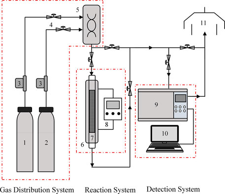
FIGURE 1. Schematic of the CO2 adsorption and desorption experimental system: 1) N2; 2) CO2; 3) mass flow meters; 4) valve; 5) mixing tank; 6) tubular furnace; 7) adsorber; 8) temperature controller; 9) CO2 analysis instrument; 10) data recording system; 11) exhaust system.
The CO2 adsorption capacity on a fixed bed can be calculated by
where q is the CO2 adsorption capacity of per gram adsorbent, mmol/g; M is the mass of the adsorbent, g; Q is the flow of the inlet gas, cm3/min; c0 and c are the CO2 concentrations of the inlet gas and outlet gas, respectively, vol%; t is the adsorption time, min; T0 is 273 K; T is the adsorption temperature, K; and Vm is the molar volume of the gas, 22.4 ml/mmol.
The regeneration degree is defined as follows:
where mreg is the CO2 adsorption capacity of the regenerated WIRAC and m1 is the CO2 adsorption capacity of the fresh WIRAC.
Figure 2 shows the N2 adsorption–desorption isotherm of WIRAC at -196 °C. On the basis of adsorption isotherm classification and adsorption hysteresis loops of the IUPAC (International Union of Pure and Applied Chemistry) (Brunauer et al., 1940; Sing et al., 1985), WIRAC presents a type I adsorption isotherm and H4 hysteresis loop. The pore structure parameters can be calculated by the N2 adsorption–desorption isotherm. Table 1 shows the pore structure parameters of WIRAC, and Figure 3 shows the pore size distributions of WIRAC by the DFT model. As shown in Figure 3, the pore sizes are in the range of 0.9–3.6 nm, especially 0.9–1.25 nm, which is suitable for CO2 adsorption (the dynamic diameter of CO2 is 0.33 nm).
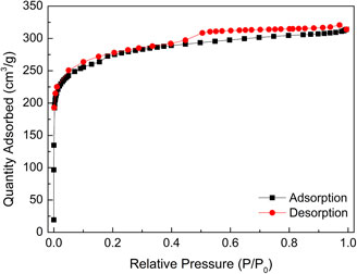
FIGURE 2. N2 adsorption–desorption isotherm of WIRAC.

TABLE 1. Pore structure parameters of WIRAC.
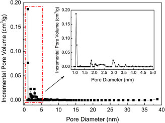
FIGURE 3. Pore size distributions of WIRAC by the DFT model.
In the research of adsorption bed experiments, the breakthrough curve is very important. The so-called breakthrough curve shows that the mixture gas enters into the adsorption bed continuously and the strong adsorbate gas can be detected in the outlet, and until the concentration of the strong adsorbate gas in the outlet is the same as the concentration of the gas in the inlet. In the following experiments, the effects of different operating parameters on CO2 adsorption performance of WIRAC were researched.
Figure 4 shows CO2 adsorption properties at different adsorption temperatures. As shown in Figures 4A,B, as the adsorption temperature increases, the breakthrough curves move to the left and the breakthrough time reduces. The two points of the breakthrough curve are important, and they are 5% (the concentration of the strong adsorbate gas in the outlet divided by the concentration of the gas in the inlet) and 95%, respectively. The point of 5% expresses the adsorption bed begins to be broken through, and the point of 95% expresses the adsorption bed is almost broken through completely. The CO2 adsorption capacity reduces with the increasing adsorption temperature. There are two reasons leading to the situation. One is that the adsorption process is an exothermal reaction. For an exothermal reaction, the reaction will move toward the reverse direction with the increase of temperature. Thus, adsorption can be inhibited, which is not conducive to the adsorption process. The other is that as the temperature increases, CO2 molecules can get more energy. This will lead to more adsorbed CO2 molecules removed from the surface of WIRAC. The two reasons lead to the reduction of CO2 adsorption capacity with the increase of adsorption temperature. Figure 4B demonstrates the CO2 adsorption capacity of different situations. The adsorption capacity of 5% is named
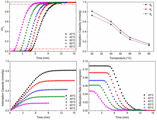
FIGURE 4. CO2 adsorption properties at different adsorption temperatures: (A) breakthrough curves; (B) adsorption capacity; (C) adsorption process; (D) adsorption rate.
As revealed in Figures 4C,D, with the increase of temperature, the CO2 adsorption equilibrium time reduces, which is the same as the result of breakthrough curves. And as the temperature increases, the CO2 adsorption rate reduces. Theoretically, the adsorption rate should increase with the increase of temperature. However, the result was contrary to the theoretical result. As the temperature increases, the rates of adsorption and desorption both increase, but the desorption rate can be affected more than the adsorption rate. This leads to the CO2 adsorption rate reducing with the increase of adsorption temperature.
CO2 adsorption in the lower temperature not only makes the time of breakthrough be longer but also makes the CO2 adsorption capacity and adsorption rate be higher. Hence, CO2 can be adsorbed consecutively for a long time without changing the pipeline frequently to switch adsorption and desorption processes. And in this situation, the CO2 adsorption capacity and adsorption rate are both higher. The temperature of flue gas is about 50–80°C, which is dependent on the difference of desulfurization and denitrification processes. In this range, it is not conducive to CO2 adsorption. Therefore, the temperature of flue gas should be properly reduced, or development a kind of adsorbent which has a good adsorption capacity at the temperature of 50–80°C.
Figure 5 shows CO2 adsorption properties at different gas flows. In Figures 5A,B, with the increase of gas flow, the breakthrough curves move to the left and the breakthrough time and CO2 adsorption capacity reduce. With the increase of gas flow, the total amounts of gas flowing and CO2 molecules through the adsorbent increase per unit time and breakthrough time shortens. However, the larger gas flow can sweep the adsorbed CO2 molecules and make some adsorbed CO2 molecules desorb. Hence, the CO2 adsorption capacity reduces with the increase of gas flow. Figure 5B shows the CO2 adsorption capacity of different situations.
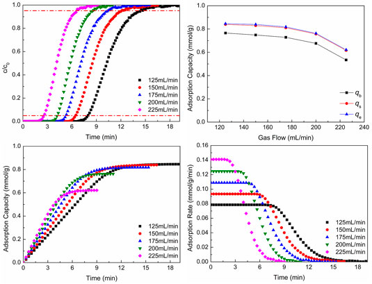
FIGURE 5. CO2 adsorption properties at different gas flows: (A) breakthrough curves; (B) adsorption capacity; (C) adsorption process; (D) adsorption rate.
From the results of Figures 5C,D, it can be seen that as the gas flow increases, the CO2 adsorption equilibrium time reduces, which is the same as the result of breakthrough curves. And with the increase of flow gas, the adsorption rate increases. With the increase of gas flow, the total amounts of gas flow and CO2 molecules through the adsorbent increase per unit time, which makes the total gas pressure increase and the reaction move toward the direction of decrease of pressure reduction (the direction of CO2 adsorption). Hence, the adsorption rate increases, as the gas flow increases.
Although the larger gas flow can make the adsorption rate increase, the CO2 adsorption capacity per unit mass of adsorbent and breakthrough time reduce. The reduction of breakthrough time leads to the change of pipeline frequently to switch adsorption and desorption processes, and the reduction of adsorption capacity cannot make the adsorbent be utilized better. In the actual production, the total amount of flue gas is unchanged generally. In order to reduce the flue gas flow, the flue gas can be bypassed to enter into parallel adsorption beds. In this way, not only switching pipes frequently can be reduced, but also WIRAC can be utilized better.
Figure 6 shows CO2 adsorption properties at different CO2 concentrations. As shown in Figures 6A,B, as the CO2 concentration increases, the breakthrough curves move to the left and the breakthrough time reduces, but the CO2 adsorption capacity increases. With the increase of CO2 concentration, the total amount of CO2 molecules through the adsorbent increases per unit time and breakthrough time shortens. The larger reactant concentration (CO2 concentration) promotes the adsorption reaction to move toward the direction of positive reaction (the direction of CO2 adsorption), so the CO2 adsorption capacity increases. Figure 6B shows the CO2 adsorption capacity of different situations.
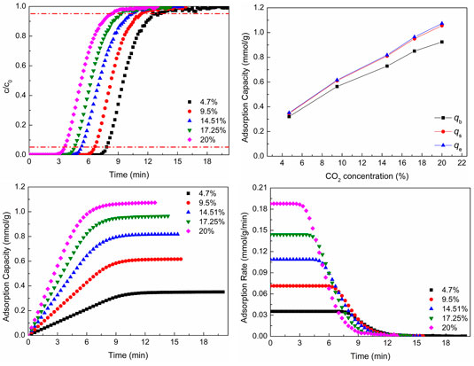
FIGURE 6. CO2 adsorption properties at different CO2 concentrations: (A) breakthrough curves; (B) adsorption capacity; (C) adsorption process; (D) adsorption rate.
As revealed in Figures 6C,D, as the CO2 concentration increases, the CO2 adsorption equilibrium time reduces, which is the same as the result of breakthrough curves, and the CO2 adsorption capacity and adsorption rate increase with the increase of CO2 concentration. As the CO2 concentration increases, the total amount of CO2 molecules through the adsorbent increases per unit time, which is advantageous to moving toward the direction of positive reaction (the direction of CO2 adsorption). Hence, the CO2 adsorption rate increases. The increase of adsorption rate makes the adsorption equilibrium time reduce.
The lager CO2 concentration not only increases the adsorption capacity but also promotes the adsorption rate, which is advantageous to CO2 adsorption. However, the lager CO2 concentration can reduce the breakthrough time and make the adsorbent be regenerated frequently, which is disadvantageous to the utilization of adsorbent. The CO2 concentration of flue gas is dependent on the kind of fuel, the process, and the status of combustion. When the fuel, process, and status of combustion are determined, the CO2 concentration of flue gas is almost unchanged. In general, the high purity of product gas (CO2 gas) cannot be obtained by only one adsorption–desorption cycle. That is, the adsorption of low CO2 concentration needs more time to obtain high purity of product gas, while the high CO2 concentration needs less time. So, the number of adsorption beds of high CO2 concentration should be more than that of low CO2 concentration in order to make sure CO2 adsorption be carried out continuously.
Figure 7 shows CO2 adsorption properties at different adsorbent filling contents. In Figures 7A,B, with the increase of adsorbent filling content, the breakthrough curves move to the right and the breakthrough time and the total CO2 adsorption capacity increase, but the adsorption capacity per mass of adsorbent reduces. As the adsorbent filling content increases, that is, with the increase of the height of adsorbent, the time of gas flowing through the adsorbent bed increases, so the breakthrough time increases. The more adsorbent makes some adsorbent could not contact with CO2 gas. Although the total adsorption capacity increases, the adsorption capacity per mass of adsorbent reduces. Figure 7B shows the CO2 adsorption capacity of different situations.
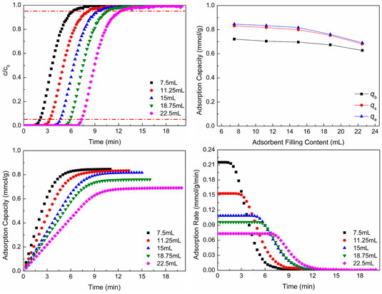
FIGURE 7. CO2 adsorption properties at different adsorbent filling contents: (A) breakthrough curves; (B) adsorption capacity; (C) adsorption process; (D) adsorption rate.
As revealed in Figures 7C,D, as the adsorbent filling content increases, the CO2 adsorption equilibrium time increases, which is the same as the result of breakthrough curves, but the CO2 adsorption capacity per mass of adsorbent and adsorption rate reduce with the increase of adsorbent filling content.
The larger amount of adsorbent makes the breakthrough time increase, but the CO2 adsorption capacity per mass of adsorbent and adsorption rate reduce. The larger amount of adsorbent also leads to the further decrease of pressure drop of gas, and the adsorbent cannot be utilized effectively, which is disadvantageous to CO2 adsorption. However, the smaller amount of adsorbent makes the CO2 adsorption capacity per mass of adsorbent and adsorption rate be bigger, and the breakthrough time is small, which is disadvantageous to the cycle of adsorbent. Hence, the amount of adsorbent should be chosen according to the actual situation. In this way, the breakthrough time is enough, and the adsorbent can be utilized well.
The CO2 adsorption capacity of WIRAC has been compared with that of some other ACs. And the comparison results can be seen in Table 2. As shown in Table 2, the adsorption capacity of WIRAC is just at a middle level. And in consideration of the precursor of WIRAC, WIRAC shows great potential as an adsorbent for post-combustion CO2 capture.
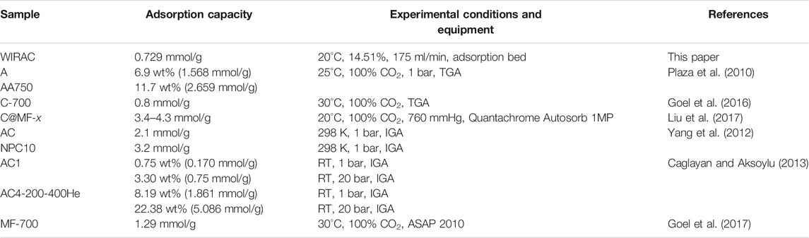
TABLE 2. Adsorption capacity of CO2 by ACs in different literature studies.
After the CO2 adsorption process, the WIRAC is regenerated and can be recycled. The different operation parameters can affect the desorption properties of WIRAC. In the following experiments, the effect of different desorption temperatures and sweep gas flows on CO2 desorption performance of WIRAC was researched. And the sweep gas in the CO2 desorption process is pure N2.
Figure 8 shows CO2 desorption properties at different desorption temperatures. As shown in Figure 8A, at the chosen experimental desorption temperature, as the desorption temperature increases, the CO2 concentration of desorption gas increases. Although CO2 concentration increases to a certain extent, the magnitude of increase is not significant, and the time of desorption increases. The higher CO2 concentration of desorption gas dependent on a higher desorption temperature makes the time of CO2 concentration reduction be longer than the lower CO2 concentration in a certain condition of sweep gas flow. So, the higher the desorption temperature is, the longer the desorption time will be. As revealed in Figure 8B, at the chosen experimental desorption temperature, the second CO2 adsorption capacity is almost the same as the first adsorption capacity, and the regeneration degree of WIRAC remains at about 1.0. It indicates that, at the chosen experimental desorption temperature, the WIRAC can be regenerated well and the CO2 adsorption capacity of regenerated WIRAC is not affected by the desorption temperature.
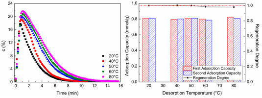
FIGURE 8. CO2 desorption properties at different desorption temperatures: (A) CO2 desorption concentration; (B) adsorption capacity and regeneration degree.
From the results of Figure 8, it can be seen that, at the chosen experimental desorption temperature, the WIRAC can be regenerated well and the higher purity of CO2 depends on the higher desorption temperature. With the increase of desorption temperature, the energy required for regeneration increases, while the increased scope of the purity of CO2 in product gas is not big. In order to obtain the higher purity CO2 product gas, increasing the desorption temperature simply makes the input more than the output and lost than gained. Hence, a suitable desorption temperature not only makes the WIRAC be regenerated well but also makes the input energy be not too much and the purity of CO2 in product gas be relatively high.
Figure 9 shows CO2 desorption properties at different sweep gas flows. As shown in Figure 9A, with the increase of sweep gas flow, the CO2 concentration in desorption gas and desorption time reduce. When the adsorption process and desorption condition are unchanged, the amount of CO2 in desorption gas is unchanged, too. As the sweep gas flow increases, the CO2 in desorption gas is diluted. Hence, the CO2 concentration in desorption gas and desorption time reduce with the increase of sweep gas flow. As revealed in Figure 9B, the second CO2 adsorption capacity is almost the same as the first adsorption capacity, and the regeneration degree of WIRAC remains at about 1.0 at different sweep gas flows. This indicates that the WIRAC can be regenerated well and the CO2 adsorption capacity of regenerated WIRAC is not affected by the sweep gas flow.
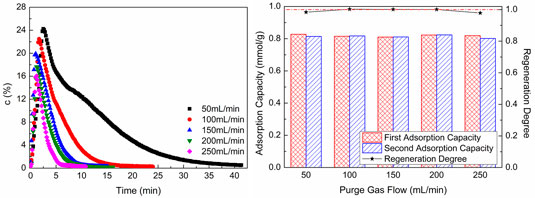
FIGURE 9. CO2 desorption properties at different sweep gas flows: (A) CO2 desorption concentration; (B) adsorption capacity and regeneration degree.
From the results of Figure 9, it can be seen that no matter what the sweep gas flow is, the WIRAC can be regenerated completely at the chosen regeneration condition. The regeneration of WIRAC is almost not affected by the sweep gas flow, while the CO2 concentration in product gas is affected by the sweep gas flow. The bigger the sweep gas flow, the lower the CO2 purity in product gas. And the shorter the desorption time is, the faster the desorption process will be. In the actual production, the suitable sweep gas flow should be chosen, so not only the higher CO2 purity in product gas can be obtained, but also the faster regeneration of WIRAC can be got.
In this paper, WIRAC is utilized as an adsorbent for CO2 adsorption. The adsorption and desorption properties of WIRAC on a fixed bed were researched. In the adsorption process, with the increase of adsorption temperature, the CO2 adsorption capacity and adsorption rate decrease; as the gas flow increases, the CO2 adsorption capacity decreases, but the adsorption rate increases; with the increase of CO2 concentration, the CO2 adsorption capacity and adsorption rate increase; as the adsorbent filling content increases, the CO2 adsorption capacity and adsorption rate increase. In order to make the CO2 adsorption capacity and adsorption rate of WIRAC be higher, the adsorption temperature should be low; the flue gas should be bypassed to enter into parallel adsorption beds; the amount of adsorbent should be chosen according to the actual situation. In the desorption process, the higher the desorption temperature and the smaller the sweep gas flow, the higher the CO2 purity of product gas and the longer the desorption time. Due to obtaining high CO2 purity of product gas in a short time, the desorption temperature and sweep gas flow should be chosen with suitable values.
The original contributions presented in the study are included in the article/Supplementary Material, and further inquiries can be directed to the corresponding author.
All authors listed have made a substantial, direct, and intellectual contribution to the work and approved it for publication.
This research was supported by the Jiangsu Planned Projects for Postdoctoral Research Funds (2019K119), Jiangsu Planned Projects for Postdoctoral Daily Funds (2019Z003), and Open Research Fund of Jiangsu Province Key Laboratory of Environmental Engineering (ZZ2020003).
The authors declare that the research was conducted in the absence of any commercial or financial relationships that could be construed as a potential conflict of interest.
All claims expressed in this article are solely those of the authors and do not necessarily represent those of their affiliated organizations, or those of the publisher, the editors, and the reviewers. Any product that may be evaluated in this article, or claim that may be made by its manufacturer, is not guaranteed or endorsed by the publisher.
Álvarez-Gutiérrez, N., Gil, M. V., Rubiera, F., and Pevida, C. (2017). Kinetics of CO2 Adsorption on Cherry Stone-Based Carbons in CO2/CH4 Separations. Chem. Eng. J. 307, 249–257. doi:10.1016/j.cej.2016.08.077
Bao, Z., Alnemrat, S., Yu, L., Vasiliev, I., Ren, Q., Lu, X., et al. (2011). Kinetic Separation of Carbon Dioxide and Methane on a Copper Metal-Organic Framework. J. Colloid Interf. Sci. 357 (2), 504–509. doi:10.1016/j.jcis.2011.01.103
Botomé, M. L., Poletto, P., Junges, J., Perondi, D., Dettmer, A., and Godinho, M. (2017). Preparation and Characterization of a Metal-Rich Activated Carbon from CCA-Treated wood for CO 2 Capture. Chem. Eng. J. 321, 614–621. doi:10.1016/j.cej.2017.04.004
Bratek, K., Bratek, W., and Kułażyński, M. (2002). Carbon Adsorbents from Waste Ion-Exchange Resin. Carbon 40 (12), 2213–2220. doi:10.1016/s0008-6223(02)00091-x
Brunauer, S., Deming, L. S., Deming, W. E., and Teller, E. (1940). On a Theory of the van der Waals Adsorption of Gases. J. Am. Chem. Soc. 62, 1723–1732. doi:10.1021/ja01864a025
Caglayan, B. S., and Aksoylu, A. E. (2013). CO2 Adsorption on Chemically Modified Activated Carbon. J. Hazard. Mater. 252-253, 19–28. doi:10.1016/j.jhazmat.2013.02.028
Chen, Y., Lv, D., Wu, J., Xiao, J., Xi, H., Xia, Q., et al. (2017). A New MOF-505@GO Composite with High Selectivity for CO 2/CH 4 and CO 2/N 2 Separation. Chem. Eng. J. 308, 1065–1072. doi:10.1016/j.cej.2016.09.138
Cheung, O., Bacsik, Z., Liu, Q., Mace, A., and Hedin, N. (2013). Adsorption Kinetics for CO2 on Highly Selective Zeolites NaKA and Nano-NaKA. Appl. Energ. 112, 1326–1336. doi:10.1016/j.apenergy.2013.01.017
Delgado, J. A., Águeda, V. I., Uguina, M. A., Brea, P., and Grande, C. A. (2017). Comparison and Evaluation of Agglomerated MOFs in Biohydrogen Purification by Means of Pressure Swing Adsorption (PSA). Chem. Eng. J. 326, 117–129. doi:10.1016/j.cej.2017.05.144
Goel, C., Bhunia, H., and Bajpai, P. K. (2017). Prediction of Binary Gas Adsorption of CO2/N2 and Thermodynamic Studies on Nitrogen Enriched Nanostructured Carbon Adsorbents. J. Chem. Eng. Data 62, 214–225. doi:10.1021/acs.jced.6b00604
Goel, C., Kaur, H., Bhunia, H., and Bajpai, P. K. (2016). Carbon Dioxide Adsorption on Nitrogen Enriched Carbon Adsorbents: Experimental, Kinetics, Isothermal and Thermodynamic Studies. J. CO2 Utilization 16, 50–63. doi:10.1016/j.jcou.2016.06.002
Gun’ko, V. M., Leboda, R., Skubiszewska-Zięba, J., Charmas, B., and Oleszczuk, P. (2005). Carbon Adsorbents from Waste Ion-Exchange Resins. Carbon 43 (6), 1143–1150. doi:10.1016/j.carbon.2004.09.032
Hoseinzadeh Hesas, R., Wan Daud, W. M. A., Sahu, J. N., and Arami-Niya, A. (2013). The Effects of a Microwave Heating Method on the Production of Activated Carbon from Agricultural Waste: A Review. J. Anal. Appl. Pyrolysis 100, 1–11. doi:10.1016/j.jaap.2012.12.019
Jiao, J., Cao, J., Xia, Y., and Zhao, L. (2016). Improvement of Adsorbent Materials for CO 2 Capture by Amine Functionalized Mesoporous Silica with Worm-Hole Framework Structure. Chem. Eng. J. 306, 9–16. doi:10.1016/j.cej.2016.07.041
Kierzkowska, A. M., Poulikakos, L. V., Broda, M., and Müller, C. R. (2013). Synthesis of Calcium-Based, Al2O3-Stabilized Sorbents for CO2 Capture Using a Co-Precipitation Technique. Int. J. Greenhouse Gas Control. 15, 48–54. doi:10.1016/j.ijggc.2013.01.046
Kishor, R., and Ghoshal, A. K. (2016). Polyethylenimine Functionalized As-Synthesized KIT-6 Adsorbent for Highly CO2/N2 Selective Separation. Energy Fuels 30 (11), 9635–9644. doi:10.1021/acs.energyfuels.6b02082
Krishna, R., and van Baten, J. M. (2012). A Comparison of the CO2 Capture Characteristics of Zeolites and Metal-Organic Frameworks. Separat. Purif. Technol. 87, 120–126. doi:10.1016/j.seppur.2011.11.031
Liu, L., Xie, Z.-H., Deng, Q.-F., Hou, X.-X., and Yuan, Z.-Y. (2017). One-Pot Carbonization Enrichment of Nitrogen in Microporous Carbon Spheres for Efficient CO2 Capture. J. Mater. Chem. A. 5, 418–425. doi:10.1039/c6ta09782k
Ozcan, D. C., Ahn, H., and Brandani, S. (2013). Process Integration of a Ca-Looping Carbon Capture Process in a Cement Plant. Int. J. Greenhouse Gas Control. 19, 530–540. doi:10.1016/j.ijggc.2013.10.009
Plasynski, S. I., Litynski, J. T., McIlvried, H. G., and Srivastava, R. D. (2009). Progress and New Developments in Carbon Capture and Storage. Crit. Rev. Plant Sci. 28 (3), 123–138. doi:10.1080/07352680902776440
Plaza, M. G., Pevida, C., Martín, C. F., Fermoso, J., Pis, J. J., and Rubiera, F. (2010). Developing almond Shell-Derived Activated Carbons as CO2 Adsorbents. Separat. Purif. Technol. 71, 102–106. doi:10.1016/j.seppur.2009.11.008
Samanta, A., Zhao, A., Shimizu, G. K. H., Sarkar, P., and Gupta, R. (2012). Post-Combustion CO2 Capture Using Solid Sorbents: A Review. Ind. Eng. Chem. Res. 51 (4), 1438–1463. doi:10.1021/ie200686q
Sanz-Pérez, E. S., Dantas, T. C. M., Arencibia, A., Calleja, G., Guedes, A. P. M. A., Araujo, A. S., et al. (2017). Reuse and Recycling of Amine-Functionalized Silica Materials for CO 2 Adsorption. Chem. Eng. J. 308, 1021–1033. doi:10.1016/j.cej.2016.09.109
Shi, Q., Li, A., Zhu, Z., and Liu, B. (2013). Adsorption of Naphthalene onto a High-Surface-Area Carbon from Waste Ion Exchange Resin. J. Environ. Sci. 25 (1), 188–194. doi:10.1016/s1001-0742(12)60017-5
Sing, K. S. W., Everett, D. H., Haul, R. A. W., Moscou, L., Pierotti, R. A., Rouquerol, J., et al. (1985). Reporting Physisorption Data for Gas Solid Systems with Special Reference to the Determination of Surface Area and Porosity. Pure Appl. Chem. 54, 603–619.
Wang, D., Ma, X., Sentorun-Shalaby, C., and Song, C. (2012). Development of Carbon-Based "Molecular Basket" Sorbent for CO2 Capture. Ind. Eng. Chem. Res. 51 (7), 3048–3057. doi:10.1021/ie2022543
Wang, M., Yao, L., Wang, J., Zhang, Z., Qiao, W., Long, D., et al. (2016). Adsorption and Regeneration Study of Polyethylenimine-Impregnated Millimeter-Sized Mesoporous Carbon Spheres for Post-combustion CO2 Capture. Appl. Energ. 168, 282–290. doi:10.1016/j.apenergy.2016.01.085
Wang, Q., Luo, J., Zhong, Z., and Borgna, A. (2011). CO2 Capture by Solid Adsorbents and Their Applications: Current Status and New Trends. Energy Environ. Sci. 4 (1), 42–55. doi:10.1039/c0ee00064g
Watabe, T., and Yogo, K. (2013). Isotherms and Isosteric Heats of Adsorption for CO2 in Amine-Functionalized Mesoporous Silicas. Separat. Purif. Technol. 120, 20–23. doi:10.1016/j.seppur.2013.09.011
Wee, J.-H. (2013). A Review on Carbon Dioxide Capture and Storage Technology Using Coal Fly Ash. Appl. Energ. 106, 143–151. doi:10.1016/j.apenergy.2013.01.062
Wei, M., Yu, Q., Duan, W., Zuo, Z., Hou, L., and Dai, J. (2018). CO2adsorption and Desorption Performance of Waste Ion-Exchange Resin-Based Activated Carbon. Environ. Prog. Sustain. Energ. 37 (2), 703–711. doi:10.1002/ep.12743
Wei, M., Yu, Q., Mu, T., Hou, L., Zuo, Z., and Peng, J. (2016). Preparation and Characterization of Waste Ion-Exchange Resin-Based Activated Carbon for CO2 Capture. Adsorption 22 (3), 385–396. doi:10.1007/s10450-016-9787-8
Yang, H., Yuan, Y., and Tsang, S. C. E. (2012). Nitrogen-enriched Carbonaceous Materials with Hierarchical Micro-Mesopore Structures for Efficient CO2 Capture. Chem. Eng. J. 185-186, 374–379. doi:10.1016/j.cej.2012.01.083
Zhang, D., Cheng, W., Ma, J., and Li, R. (2016). Influence of Activated Carbon in Zeolite X/Activated Carbon Composites on CH4/N2 Adsorption Separation Ability. Adsorption 22 (8), 1129–1135. doi:10.1007/s10450-016-9836-3
Keywords: CO2 adsorption, waste ion-exchange resin–based activated carbon, fixed bed, breakthrough curve, desorption
Citation: Wei M and Zhao Q (2021) CO2 Adsorption and Desorption by Waste Ion-Exchange Resin–Based Activated Carbon on Fixed Bed. Front. Energy Res. 9:772710. doi: 10.3389/fenrg.2021.772710
Received: 08 September 2021; Accepted: 28 September 2021;
Published: 02 November 2021.
Edited by:
Siyi Luo, Qingdao University of Technology, ChinaReviewed by:
Lu Chen, Dalian University of Technology, ChinaCopyright © 2021 Wei and Zhao. This is an open-access article distributed under the terms of the Creative Commons Attribution License (CC BY). The use, distribution or reproduction in other forums is permitted, provided the original author(s) and the copyright owner(s) are credited and that the original publication in this journal is cited, in accordance with accepted academic practice. No use, distribution or reproduction is permitted which does not comply with these terms.
*Correspondence: Mengqi Wei, bWVuZ3FpX3dlaUAxNjMuY29t
Disclaimer: All claims expressed in this article are solely those of the authors and do not necessarily represent those of their affiliated organizations, or those of the publisher, the editors and the reviewers. Any product that may be evaluated in this article or claim that may be made by its manufacturer is not guaranteed or endorsed by the publisher.
Research integrity at Frontiers
Learn more about the work of our research integrity team to safeguard the quality of each article we publish.