 Yong Zhu1
 Yi Yang
- 1Shenzhen Jingquanhua Electronics Co., Ltd., Shenzhen, China
- 2National-Local Joint Engineering Laboratory of Digitalize Electrical Design Technology, Wenzhou University, Wenzhou, China
- 3College of Electrical and Information Engineering, Hunan Institute of Engineering, Xiangtan, China
In order to further improve the device utilization of a modular inverter system after the failure of a single inverter unit, a silicon (Si)/silicon-carbide (SiC) hybrid switch with high redundancy can be taken to achieve this goal. However, when the failure of the Si/SiC hybrid switches in the inverter unit occurs, the performance of this modular inverter adopting the fixed switching strategy (Fixed switching pattern and switching frequency) may be reduced. In this paper, a redundancy management strategy is proposed to prevent the performance of the Si/SiC hybrid switch-based modular inverter from reducing after the failure of the Si/SiC hybrid switches occurs. Taking the modular inverter system composed of two inverter units as an example, the experiment results demonstrate that compared to the healthy operating conditions, the increase of the voltage’s THD is smaller than 1.4%, and the increase of the total loss is smaller than 0.89%.
1 Introduction
A modular inverter system is composed of multiple inverter units in parallel, which has high reliability (Zou et al., 2018). The power devices inside each inverter unit are the key to the reliable operation of the inverter unit. A silicon (Si)/silicon-carbide (SiC) hybrid switch is considered to be the core of high-power density, high efficiency, high reliability, and low-cost inverter applications. Meanwhile, it is composed of two switches in parallel (Huang et al., 2015; Jiang et al., 2020), which brings higher redundancy to the inverters. The current application is mainly based on the pure Si IGBT and the pure SiC MOSFET. However, due to the theoretical limit of performance determined by the characteristics of the Si material, the development of Si IGBT has encountered a bottleneck (Fathi et al., 2018; Peng et al., 2019a; Shi et al., 2020). Moreover, SiC MOSFETs are currently still five times more expensive than their silicon insulated-gate bipolar transistor (IGBT) counterparts, and this cost barrier is still one of the main reasons why silicon carbide has not been recognized by the larger market (Madishetti et al., 2016; Sebaaly et al., 2016). Hybrid devices exhibit not only excellent performance and cost tradeoff but also inherent switch-level redundancy for potential power converter fault-tolerant operation. Even if the SiC MOSFET or Si IGBT has an open-circuit fault, the hybrid device can still ensure the stable operation of the inverter unit, which greatly avoids the short-term idle behavior of the faulty inverter unit after the device fails (Li et al., 2020; Peng et al., 2020).
At present, the research on the redundancy strategy of a single inverter unit has been proposed. In Khanaki et al., 2019, the author integrated a single inverter into an extra low-voltage (ELV) battery module and modularized it and compared the reliability of the 48 V battery module with different redundancy strategies through experiments. In Yu et al., 2020, a five-level inverter single-tube open-circuit fault tolerance method based on redundant space vector optimization and topology reconstruction was proposed, and a new fault circuit space vector pulse width modulation control strategy was obtained, but the maximum output voltage of the inverter will be reduced to 3/4 of the normal inverter voltage. For many types of multilevel circuits, the voltage will be reduced to some extent after the failure occurs (Lee and Lee, 2016; Lee and Lai, 2021; Guan and Liu, 1109). In these articles, it may be necessary to lower the voltage to reduce the device pressure after a failure occurs, which is not sustainable for many applications. In Zhang et al., 2018, the input-series-output-series (ISOS) inverter combined system is proposed, and a hot plugging scheme dedicated to the ISOS grid-connected inverter system is put forward to actualize redundancy. In Qu et al., 2017, the input-series-output-series connection scheme is also used in the high-voltage DC/DC converters. However, there are few fault-tolerant strategies for the topology proposed in this paper, and the effective fault-tolerant strategy is urgently needed.
In order to solve these problems, a redundancy management strategy is proposed for the Si/SiC hybrid switch-based modular inverter system. It includes the fault-tolerant strategy of the switch-level and fault-tolerant strategy of the system level. When the failure of the Si/SiC hybrid switches occurs, the switch-level fault-tolerant strategy can improve the reliability and performance of a single inverter unit, and the system-level fault-tolerant strategy can improve the reliability and performance of the Si/SiC hybrid switch-based modular inverter system. Therefore, the performance of the Si/SiC hybrid switch-based modular inverter can be prevented from reducing after the failure occurs.
The rest of this paper is organized as follows: in Section 2, the redundancy topology of the Si/SiC hybrid switch-based modular inverter system is analyzed. In Section 3, a redundant fault-tolerant control strategy is proposed. In Section 4, experiments are presented. Section 5 concludes the paper.
2 Redundant Topology of the Si/SiC Hybrid Switch-Based Modular Inverter System
2.1 Redundant Topology Analysis of the Si/SiC Hybrid Switch-Based Modular Inverter System
This section analyzes the topology of the Si/SiC hybrid switch-based modular inverter system at first. Then, the switch-level fault tolerance of the Si/SiC hybrid switch and the system-level fault tolerance of the modular inverter system are analyzed. In fact, for the system-level fault tolerance, only the system-level changes due to the failure of the Si/SiC hybrid switch are considered. Meanwhile, the fault diagnosis method of the power electronic switches has been successfully applied in various converters, so the fault diagnosis procedure will not be considered in this paper (Dhumale et al., 2017; Yang et al., 2018). Details are shown as follows:
2.1.1 Structure of the Si/SiC Hybrid Switch-Based Modular Inverter System
Just taking two three-phase inverter units as examples, the topology of the Si/SiC hybrid switch-based modular inverter system is shown in Figure 1. As can be seen from Figure 1, UDC1/UDC2, T1n/T2n (n = 1, 2, … , 6), L1/L2), Cs1/Cs2, and Z represent the DC voltage, Si/SiC hybrid switches, filter capacitor, filter inductance, and load, respectively. VGM, VGI, ton, and toff represent the gate drive signal of the SiC MOSFET, the gate drive signal of the Si IGBT, the turn-on delay time, and the turn-off delay time, respectively. The Si/SiC hybrid switch is composed of the large-capacity Si IGBT and small-capacity SiC MOSFET in parallel, and the SiC MOSFET is generally turned on earlier and turned off later to achieve the lower switching loss of the Si/SiC hybrid switch. In addition, there is P1 (output power of “Inverter 1”) + P2 (output power of “Inverter 2”) = P (total power of the modular inverter system).
(1) Fault-tolerant topology of the switch level
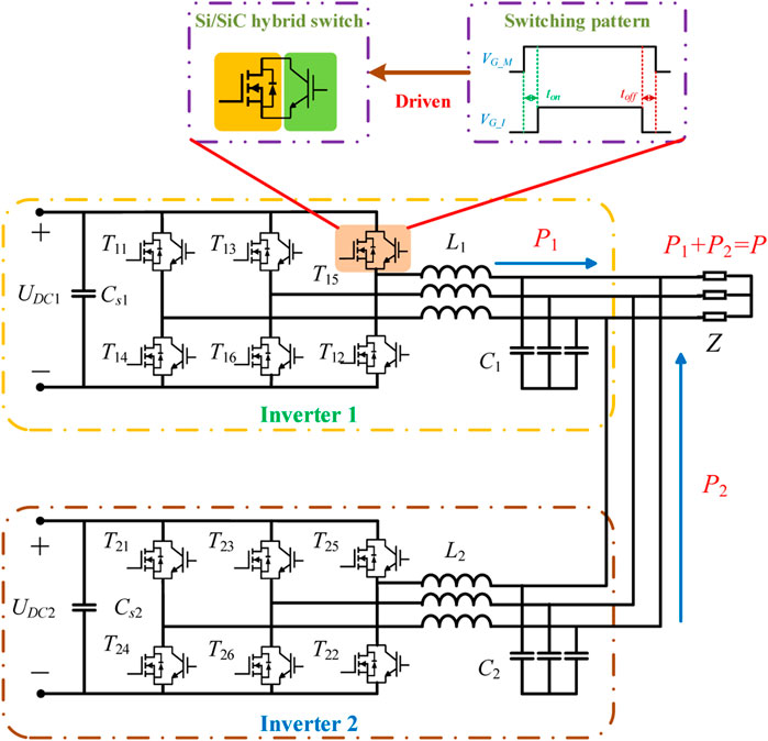
FIGURE 1. Structure of Si/SiC hybrid switch based modular inverter system.
According to Zhang et al., 2014, when the failure of the Si IGBT or SiC MOSFET inside the Si/SiC hybrid switch occurs, the switch-level fault-tolerant topology is shown in Figure 2, and details are presented in the following.
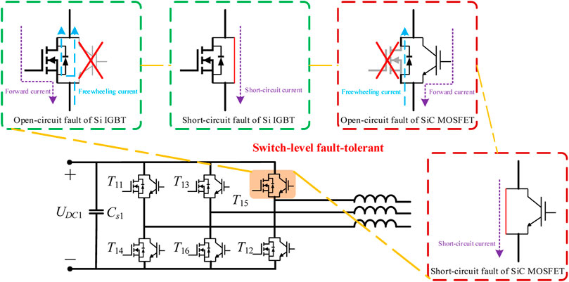
FIGURE 2. Switch-level fault-tolerant topology.
As can be seen from Figure 2, when the open-circuit fault of the Si IGBT occurs, the forward current can flow through the SiC MOSFET, and the freewheeling current can flow through the body diode or channel of the SiC MOSFET. Under these conditions, if the forward current is larger than the rated current of the SiC MOSFET, its reliability will be greatly reduced.
When the open-circuit fault of the SiC MOSFET occurs, the forward current can flow through the Si IGBT, and the freewheeling current can flow through the body diode of the SiC MOSFET. Under these conditions, the output voltage harmonics of the inverter unit will be increased, and its power loss will also be increased. Meanwhile, if the forward current is larger than the rated current of the Si IGBT, its reliability will be greatly reduced.
When the short-circuit fault of the Si IGBT or SiC MOSFET occurs, the short-circuit current will be increased sharply, resulting in the damage of the healthy Si/SiC hybrid switch.
(2) Fault-tolerant topology of the system level
Based on the switch-level fault tolerance, the system-level fault-tolerant topology is shown in Figure 3. As can be seen from Figure 3, Uo1∠θo1 (Uo2∠θo2), Up∠0, ll1 (ll2), and rl1 (rl2) represent the output voltage of the inverter unit (“Inverter 1” and “Inverter 2”), the voltage of point of common coupling (PCC), the line reactance, and the line resistance, respectively.
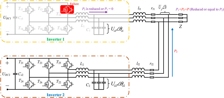
FIGURE 3. System-level fault-tolerant topology.
According to Fathi et al., 2018; Peng et al., 2019b; Li et al., 2019, there is
where Rl1 and Xl1 represent the value of the line reactance and the value of the line resistance, respectively. Assuming that there are Rl1 = Rl2, Xl1 = Xl2, sinθ01 ≈ θ01, and cosθ01 ≈ 1, when “Inverter 1” and “Inverter 2” operate in parallel, there is
According to Eq. 2, the accurate power sharing of “Inverter 1” and “Inverter 2” is affected by their own output voltage waveforms.
Taking “Inverter 1” as an example, when the open-circuit fault of the Si/SiC hybrid switch occurs, the output power of the inverter unit should be reduced to prevent its reliability from decreasing. Therefore, the output power of “Inverter 1” will be reduced, resulting in the reduction of the total power (P). Meanwhile, according to Eq. 2, if the failure of the SiC MOSFET occurs, the increase of the output voltage harmonics will increase the power circumfluence, resulting in the reduction of the accurate power sharing. Therefore, the power loss of the modular inverter system will be increased.
3 Redundancy Management Strategy
3.1 Principle of the Redundancy Management Strategy
According to the above theoretical analysis, when the failure of the Si/SiC hybrid switch occurs, this section proposes the redundancy management strategy to prevent the performance and reliability of the Si/SiC hybrid switch-based modular inverter system from greatly decreasing. The principle of the redundancy management strategy is shown in Figure 4. As can be seen from Figure 4, it comprises the redundancy management strategy of the switch level and the redundancy management strategy of the system level. For the redundancy management strategy of the switch level, the fault is detected at first. Then, the types of the fault devices (failure of the Si IGBT or SiC MOSFET) and types of the fault (open-circuit fault or short-circuit fault) are determined. Finally, the fault signals and the operating states of the single inverter are sent to the redundancy management strategy of the system level (output power level of the single inverter), and a new switching strategy for the Si/SiC hybrid switch is adopted. For the redundancy management strategy of the system level, the switch-level signals are obtained at first. Then, according to the operating states of the system-level and switch-level signals, the output power of each inverter unit is adjusted. Taking “Inverter 1” as an example, details about the redundancy management strategy of the switch level and system level are described as follows.
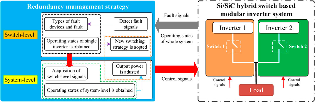
FIGURE 4. Principle of the redundancy management strategy.
3.1.1 Redundancy Management Strategy of the Switch Level
For the redundancy management strategy of the switch level, some switching strategies can be referred (Ou et al., 2020), and its classification is shown in Table 1. As can be seen from Table 1, I1max and I2max represent the rated current of the Si IGBT and SiC MOSFET, respectively. Details are presented in the following.
1) Open-circuit fault of the Si IGBT or SiC MOSFET
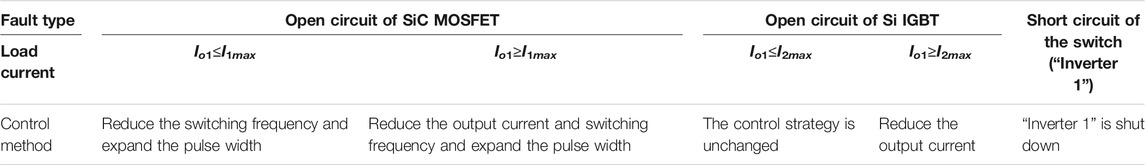
TABLE 1. Classification of the redundancy management strategy of the switch level.
When the open-circuit fault of the SiC MOSFET occurs, if the output current of “Inverter 1” (Io1) is smaller than I1max, the pulse width of the Si IGBT inside the faulty Si/SiC hybrid switch should be expanded to reduce the voltage ripples, and the switching frequency should be reduced to decrease the switching loss of “Inverter 1”. If Io1 is larger than I1max, the switching frequency should also be reduced, and the reduction of the output power can be achieved in the redundancy management strategy of the system level.
When the open-circuit fault of the Si IGBT occurs, if Io1 is smaller than I2max, the switching strategy is unchanged. If Io1 is larger than I2max, the reduction of the output power can be achieved in the redundancy management strategy of the system level.
2) Short-circuit fault of the Si IGBT or SiC MOSFET
When the short-circuit fault of the Si IGBT or SiC MOSFET occurs, “Inverter 1” must be shut down to prevent itself from being damaged by the short-circuit current.
3.1.2 Redundancy Management Strategy of the System Level
The redundancy management strategy of the system level can achieve the energy adjustment of each inverter unit when the failure of the Si/SiC hybrid switch occurs, and its principle is shown in Figure 5. As can be seen from Figure 5, detailed steps about the redundancy management strategy of the system level are shown in the following.
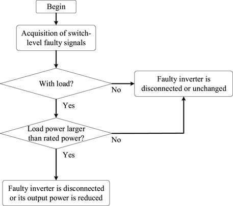
FIGURE 5. Principle of the redundancy management strategy of the system level.
Case 1 The switch-level faulty signal is obtained at first. If the fault occurs, go to the next step.
Case 2 The load status is detected. If the inverter is not running with load, the faulty inverter is disconnected or unchanged. If the inverter is running with the load, go to the next step.
Case 3 The load power is detected. If the load power is greater than that of the faulty inverter, return to the previous step. If the load power is smaller than that of the faulty inverter, go to the next step.
Case 4 The faulty inverter is disconnected, or its output power is reduced.In order to achieve the energy adjustment of each inverter, the virtual synchronous generator (VSG) control strategy is taken in this paper. The VSG control strategy enables the inverter to have the same good dynamic characteristics and parallel operation capability as the synchronous generator. In addition, it has superior power self-adjustment ability and stronger frequency inertia than the traditional droop control strategy. The formula of the torque governor and rotor motion in the VSG control strategy is written as (Liu et al., 2019; Jiang et al., 2020; Shi et al., 2020)
where Pm, Po, kω, J, D, Tm, T, ωr, and ω represent the mechanical power, the initial value of mechanical power, the coefficient of the angular frequency regulation, the virtual inertia, the damping factor, the mechanical torque, the electromagnetic torque, the angular frequency reference signal, and the output angular frequency, respectively.The formula of the excitation in the VSG control strategy is written as (Liu et al., 2019; Jiang et al., 2020; Shi et al., 2020)
where Uv, kv, Ur, Qr, and Qo represent the output voltage signal, voltage adjustment coefficient, command voltage signal, reactive power reference signal, and reactive power initial signal, respectively. In order to verify the correctness of the proposed energy management strategy, the load used in the test in this article is only a resistive load, which means that the reactive power flowing through the line is relatively small, and the impact on the result of the inverter is also small. Therefore, only the active power adjustment of each inverter is considered for the convenience of analysis. According to (3), kω can achieve this goal.
3.2 Classification of Redundant Management Strategies
Different control methods in the fault state are shown in Figure 6. As can be seen from Figure 6, I1max and I2max represent the rated current of the Si IGBT and SiC MOSFET, respectively. Details are presented in the following.
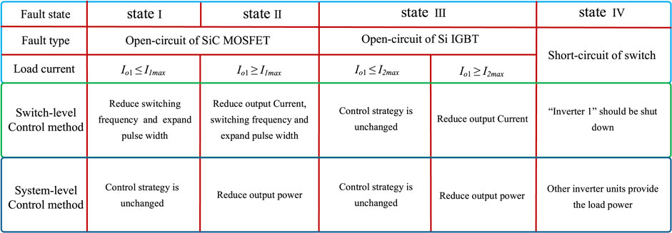
FIGURE 6. Classification of redundant management strategies.
3.2.1 Fault State I
When the open-circuit fault of the SiC MOSFET occurs, if the output current of “Inverter 1” (Io1) is smaller than I1max, the VSG parameters of “Inverter 1” remain unchanged, and the power output remains consistent with the normal state. Meanwhile, the pulse width of the Si IGBT inside the faulty Si/SiC hybrid switch should be expanded to reduce the voltage ripples, and the switching frequency should be reduced to decrease the switching loss of “Inverter 1”.
3.2.2 Fault State II
When the open-circuit fault of the Si IGBT or SiC MOSFET occurs, if the output current of “Inverter 1” (Io1) is larger than I1max, the output power of “Inverter 1” should be decreased, and the pulse width of the Si IGBT inside the faulty Si/SiC hybrid switch should be expanded. Meanwhile, the switching frequency should be reduced.
3.2.3 Fault State III
When the open-circuit fault of the Si IGBT occurs, if the output current of “Inverter 1” (Io1) is smaller than I2max, the VSG parameters of “Inverter 1” and the switching strategy are unchanged. In addition, if the output current of “Inverter 1” (Io1) is larger than I2max, the output power of “Inverter 1” should be decreased.
3.2.4 Fault State IV
When the short-circuit fault of the Si IGBT or SiC MOSFET occurs, “Inverter 1” must be shut down to prevent itself from being damaged by the short-circuit current.
4 Experimental Results
In order to verify the effectiveness of the fault-tolerant control strategy, the corresponding experimental platform is established, which is shown in Figure 7. In addition, the experimental parameters are described in Table 2. The failure of “Inverter 1” is taken as an example.
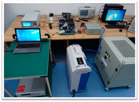
FIGURE 7. Experimental platform.
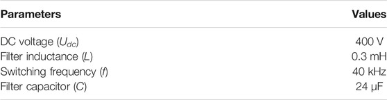
TABLE 2. Experimental parameters.
4.1 Switch-Level Redundancy Experiment
4.1.1 Open-Circuit Fault of SiC MOSFET Occurs (Load Current is Smaller than I1max)
In this case, the voltage THD and switching loss of “Inverter 1” increase. The switching loss and voltage distortion can be reduced by reducing the switching frequency.
The experimental waveforms are shown in Figure 8, including the output voltage of “Inverter 1” (Uo1), the driving voltage of the MOSFET (GMOSFET), and the driving voltage of the IGBT (GIGBT). When the redundancy management strategy of the switch level is adopted, the switching frequency reduces from 40 to 20 kHz, and the pulse width of the Si IGBT inside the faulty Si/SiC hybrid is expanded. The THD of the output voltage of “Inverter 1” under faulty conditions is 0.990%, which is close to that under the healthy conditions (1.027%). In addition, the efficiency of “Inverter 1” under faulty conditions is 97.95%, which is close to that under the healthy conditions (98.22%).
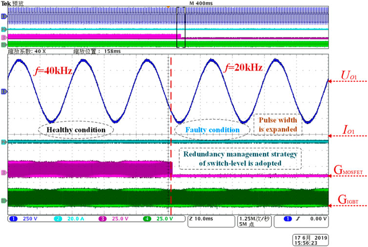
FIGURE 8. Experimental waveforms (open-circuit fault of MOSFET occurs, Io is smaller than I1max).
4.1.2 Open-Circuit Fault of Si IGBT Occurs (Load Current is Larger than I2max)
In this case, overcurrent can damage the SiC MOSFET inside the fault hybrid switch. The reliability of the modular inverter can be improved by reducing the output current of the fault inverter unit.
The experimental waveforms are shown in Figure 9. When the redundancy management strategy of the switch level is adopted, the modulation ratio m is reduced rapidly from 0.8 to 0.55, which can prevent the SiC MOSFET from being corrupted. The THD of the output voltage of “Inverter 1” under faulty conditions is 1.389%, which is close to that under the healthy conditions (1.017%). In addition, the efficiency of “Inverter 1” under faulty conditions is 97.40%, which is close to that under the healthy conditions (98.29%).
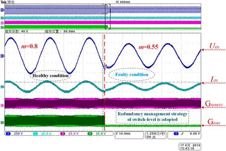
FIGURE 9. Experimental waveforms (open-circuit fault of IGBT occurs, Io is larger than I2max).
4.2 System-Level Redundancy Experiment
4.2.1 Short-Circuit Fault of the Power Switch Inside “Inverter 1” Occurs
When the short-circuit fault of the power switch inside “Inverter 1” occurs, “Inverter 1” needs to be shut down immediately. At this time, the load power is provided by “Inverter 2”.
The waveforms of active power and voltage are shown in Figure 10, including the output current of “Inverter 2” (Io2). When the redundancy management strategy of the system level is adopted, “Inverter 1” is shut down, and the output power of “Inverter 2” can be increased to full power. In fact, when the power changes, the voltage does not oscillate obviously. Meanwhile, the THD of Up before the disconnection of “Inverter 1” is 1.07%, and after the disconnection of “Inverter 1”, the THD of Up has little change (1.03%).
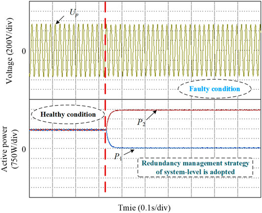
FIGURE 10. Waveforms of active power and voltage (short-circuit fault of the power switch).
4.2.2 Open-Circuit Fault of Si IGBT Inside “Inverter 1” Occurs, and Load Current is Larger than I2max
In this case, the output power of “Inverter 1” and “Inverter 2” is unchanged. The waveforms of active power and voltage are shown in Figure 11. When the fault occurs, the THD of Up is consistent with that before the failure of the Si IGBT (1.07%).
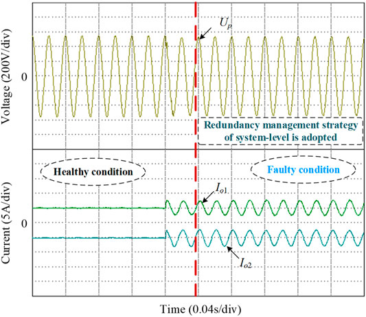
FIGURE 11. Voltage and current waveforms (open-circuit fault of Si IGBT).
4.3 Discussion
Based on the above experiments, the following conclusions can be drawn:
(1) When the open-circuit fault of Si IGBT occurs, if the redundancy management strategy of the switch level is adopted, the THD of the output voltage is close to that under the healthy conditions, and the efficiency of the inverter unit does not change much after the failure occurs. Meanwhile, the redundancy management strategy of the system level has little influence on the performance of the modular inverter system.
(2) When the short-circuit fault occurs, even if the faulty inverter unit is shut down, the output power of the healthy inverter unit can be steadily increased to the power required by the load, and the switching process of the faulty inverter has little influence on the modular inverter system.
5 Conclusion
In this paper, a fault-tolerant control strategy is proposed to improve the device utilization of the modular inverter system when the failure occurs. It consists of the redundancy management strategy of the switch level and the redundancy management strategy of the system level. The redundancy management strategy of the switch level can prevent the single inverter unit from damaging, and the redundancy management strategy of the system level can enhance the reliability and performance of the Si/SiC hybrid switch-based modular inverter system. Experimental results show that even if a bad failure occurs, it will not have a serious impact on a single inverter. Meanwhile, the modular inverter system can adjust the output power adaptively according to the demand of the faulty inverter unit to ensure the stable power supply of the load.
In fact, the fault-tolerant control strategy is applicable not only to the DC/AC converters but also to the DC/DC converters. In addition, it is also suitable for different applications, such as coastal engineering, industrial automation, electric vehicles, and other fields.
Data Availability Statement
The original contributions presented in the study are included in the article/Supplementary Material; further inquiries can be directed to the corresponding authors.
Author Contributions
YZ and ZP provided experimental ideas, YD provided experimental equipment, ZZ and ZL were responsible for technical guidance, and YY was responsible for experimental verification.
Funding
This project was supported by the State Key Laboratory of Power System and Generation Equipment (SKLD21KM05), the Hunan Provincial Natural Science Foundation of China (Grant No. 2019JJ60034), and the Scientific Research Foundation of Hunan Provincial Department of Education (No. 19A106).
Conflict of Interest
YZ and YY were employed by Shenzhen Jingquanhua Electronics Co., Ltd.
The remaining authors declare that the research was conducted in the absence of any commercial or financial relationships that could be construed as a potential conflict of interest.
Publisher’s Note
All claims expressed in this article are solely those of the authors and do not necessarily represent those of their affiliated organizations or those of the publisher, the editors, and the reviewers. Any product that may be evaluated in this article or claim that may be made by its manufacturer is not guaranteed or endorsed by the publisher.
References
Dhumale, R. B., Thombare, N. D., and Lokhande, S. D. “Modeling and Diagnosis of Open Switch Fault in Three Phase VSI,” in Proceedings of the 2017 2nd IEEE International Conference on Recent Trends in Electronics, Information & Communication Technology (RTEICT), Bangalore, May 2017, 314–319.
Fathi, A., Shafiee, Q., and Bevrani, H. (2018). Robust Frequency Control of Microgrids Using an Extended Virtual Synchronous Generator. IEEE Trans. Power Syst. 33 (6), 6289–6297. doi:10.1109/tpwrs.2018.2850880
Guan, B., and Liu, Z. (1109). Hybrid Modulation Strategy with Neutral Point Potential Balance of T-type Three-Level Converter under Switch Open-Circuit Fault. IEEE Trans. Ind. Electron., 1. doi:10.1109/TIE.2021.3120477
Huang, A. Q., Song, X., and Zhang, L. “6.5 kV Si/SiC Hybrid Power Module: An Ideal Next Step,” in Proceedings of the 2015 IEEE International Workshop on Integrated Power Packaging (IWIPP), Chicago, IL, May 2015, 64–67.
Jiang, K., Su, H., Lin, H., He, K., Zeng, H., and Che, Y. (2020). A Practical Secondary Frequency Control Strategy for Virtual Synchronous Generator. IEEE Trans. Smart Grid 11 (3), 2734–2736. doi:10.1109/tsg.2020.2974163
Khanaki, R., Walker, G. R., Ledwich, G. F., and Broadmeadow, M. A. H. “Impact of Inverter Distribution and Redundancy on Reliability of Battery-Integrated-Converter Systems,” in Proceedings of the 2019 29th Australasian Universities Power Engineering Conference (AUPEC), Nadi, Fiji, November 2019, 1–6.
Lee, J.-S., and Lee, K.-B. (2016). Open-Circuit Fault-Tolerant Control for Outer Switches of Three-Level Rectifiers in Wind Turbine Systems. IEEE Trans. Power Electron. 31 (5), 3806–3815. doi:10.1109/tpel.2015.2464803
Lee, M., and Lai, J.-S. (2021). Unified Voltage Balancing Feedforward for Three-Level Boost PFC Converter in Discontinuous and Critical Conduction Modes. IEEE Trans. Circuits Syst. 68 (1), 441–445. doi:10.1109/tcsii.2020.3003113
Li, Z., Wang, J., He, Z., Yu, J., Dai, Y., and Shen, Z. J. (2020). Performance Comparison of Two Hybrid Si/SiC Device Concepts. IEEE J. Emerg. Sel. Top. Power Electron. 8 (1), 42–53. doi:10.1109/jestpe.2019.2947252
Li, Z., Wu, Z., and Hu, W. “Control Strategy Design and Dynamic Analysis of Grid-Connected Inverter Based on Virtual Synchronous Generator,” in Proceedings of the 2019 IEEE 4th Advanced Information Technology, Electronic and Automation Control Conference (IAEAC), Chengdu, China, December 2019, 1235–1240.
Liu, G., Jing, Y., Wang, W., and Blaajerg, F. “An Improved Reactive Power Control Strategy for the Parallel Inverter System Based on VSG,” in Proceedings of the 2019 22nd International Conference on Electrical Machines and Systems (ICEMS), Harbin, China, August 2019, 1–6. doi:10.1109/icems.2019.8922222
Madishetti, S., Singh, B., and Bhuvaneswari, G. (2016). Three-Level NPC-Inverter-Based SVM-VCIMD with Feedforward Active PFC Rectifier for Enhanced AC Mains Power Quality. IEEE Trans. Industry Appl. 52 (2), 1865–1873. doi:10.1109/TIA.2015.2496906
Ou, L., Peng, Z., Liu, Z., Peng, X., and Wang, J. “Redundancy Operation of Modular Inverter Based on Si/SiC Hybrid Switch,” in Proceedings of the 2020 IEEE 9th International Power Electronics and Motion Control Conference (IPEMC2020-ECCE Asia), Nanjing, China, November-December 2020, 1880–1883. doi:10.1109/ipemc-ecceasia48364.2020.9367712
Peng, Z., Wang, J., Liu, Z., Dai, Y., Zeng, G., and Shen, Z. J. (2020). Fault-Tolerant Inverter Operation Based on Si/SiC Hybrid Switches. IEEE J. Emerg. Sel. Top. Power Electron. 8 (1), 545–556. doi:10.1109/jestpe.2019.2952170
Peng, Z., Wang, J., Wen, Y., Bi, D., Dai, Y., and Ning, Y. (2019). Virtual Synchronous Generator Control Strategy Incorporating Improved Governor Control and Coupling Compensation for AC Microgrid. IET Power Electron. 12 (6), 1455–1461. doi:10.1049/iet-pel.2018.6167
Peng, Z., Wang, J., Wen, Y., Bi, D., Dai, Y., and Ning, Y. (2019). Virtual Synchronous Generator Control Strategy Incorporating Improved Governor Control and Coupling Compensation for AC Microgrid [J]. IET Power Electron. 12 (6), 1455–1461.
Qu, L., Zhang, D., and Bao, Z. (2017). Active Output-Voltage-Sharing Control Scheme for Input Series Output Series Connected DC-DC Converters Based on a Master Slave Structure. IEEE Trans. Power Electron. 32 (8), 6638–6651. doi:10.1109/tpel.2016.2623352
Sebaaly, F., Vahedi, H., Kanaan, H. Y., Moubayed, N., and Al-Haddad, K. (2016). Design and Implementation of Space Vector Modulation-Based Sliding Mode Control for Grid-Connected 3L-NPC Inverter. IEEE Trans. Ind. Electron. 63 (12), 7854–7863. doi:10.1109/tie.2016.2563381
Shi, K., Song, W., Ge, H., Xu, P., Yang, Y., and Blaabjerg, F. (2020). Transient Analysis of Microgrids with Parallel Synchronous Generators and Virtual Synchronous Generators. IEEE Trans. Energ. Convers. 35 (1), 95–105. doi:10.1109/tec.2019.2943888
Yang, S., Tang, Y., and Wang, P. (2018). Seamless Fault-Tolerant Operation of a Modular Multilevel Converter with Switch Open-Circuit Fault Diagnosis in a Distributed Control Architecture. IEEE Trans. Power Electron. 33 (8), 7058–7070. doi:10.1109/tpel.2017.2756849
Yu, Y., Li, X., and Wei, L. (2020). Fault Tolerant Control of Five-Level Inverter Based on Redundancy Space Vector Optimization and Topology Reconfigruation. IEEE Access 8, 194342–194350. doi:10.1109/access.2020.3033805
Zhang, W., Xu, D., Enjeti, P. N., Li, H., Hawke, J. T., and Krishnamoorthy, H. S. (2014). Survey on Fault-Tolerant Techniques for Power Electronic Converters. IEEE Trans. Power Electron. 29 (12), 6319–6331. doi:10.1109/tpel.2014.2304561
Zhang, X., Fang, T., and Ruan, X. “Distributed Control and Redundancy for Input-Series-Output-Series LCL-type Grid-Connected Inverter System,” in Proceedings of the IECON 2018 - 44th Annual Conference of the IEEE Industrial Electronics Society, Washington, DC, USA, October 2018, 4365–4370. doi:10.1109/iecon.2018.8591557
Keywords: redundancy management, Si/SiC hybrid switch, inverter, energy management, parallel inverter control
Citation: Zhu Y, Peng Z, Dai Y, Zhao Z, Liu Z and Yang Y (2022) Redundancy Management Strategy for a Silicon/Silicon-Carbide Hybrid Switch-Based Modular Inverter System. Front. Energy Res. 9:768832. doi: 10.3389/fenrg.2021.768832
Received: 01 September 2021; Accepted: 13 December 2021;
Published: 23 February 2022.
Edited by:
Miguel Angel Reyes-Belmonte, Rey Juan Carlos University, SpainReviewed by:
Nasir Ahmed Algeelani, Al-Madinah International University, MalaysiaEnrique Hernández Balaguera, Rey Juan Carlos University, Spain
Copyright © 2022 Zhu, Peng, Dai, Zhao, Liu and Yang. This is an open-access article distributed under the terms of the Creative Commons Attribution License (CC BY). The use, distribution or reproduction in other forums is permitted, provided the original author(s) and the copyright owner(s) are credited and that the original publication in this journal is cited, in accordance with accepted academic practice. No use, distribution or reproduction is permitted which does not comply with these terms.
*Correspondence: Zhenxing Zhao, MjIwMDZAaG5pZS5lZHUuY24=; Yuxing Dai, ZGFpeXhAaG51LmVkdS5jbg==