 Wang Lianjie
 Wei Yanqin
94% of researchers rate our articles as excellent or good
Learn more about the work of our research integrity team to safeguard the quality of each article we publish.
Find out more
ORIGINAL RESEARCH article
Front. Energy Res., 08 December 2021
Sec. Nuclear Energy
Volume 9 - 2021 | https://doi.org/10.3389/fenrg.2021.764897
This article is part of the Research TopicReactor Physics: Methods and ApplicationsView all 27 articles
Based on the requirement of Hexagonal Casing Type Fuel Reactor (HCTFR) nuclear design and the critical physical experiment design method introduced by a single factor, 11 core critical physical experiments are proposed to validate the calculation accuracy and reliability of the nuclear design code CPLEV2. The experiment loading scheme fully takes into account the various components and more than one irradiate hole in the HCTFR core, which is used as critical physical experiment schemes successfully. According to the critical physical experiment data, the reactivity calculation deviations of all critical physical experiments are within ±1.0%. The validation results show that the nuclear design code CPLEV2 has high calculation accuracy and reliability for the core of hexagonal casing type fuel, and it can be used for HCTFR nuclear design.
The nuclear design of Hexagonal Casing Type Fuel Reactor (HCTFR) adopted nuclear design program CPLEV2, which is a specific nuclear design code of the test reactor. As the hexagonal casing fuel core, irradiate hole scheme, fuel assembly, and control rod assembly of HCTFR are different from those of the existing reactor (Xu et al., 1990; Liu et al., 2000; Tang et al., 2011), it is necessary to carry out the critical physical experiment to test the calculation accuracy and reliability of nuclear design code CPLEV2 which has been applied to the design of HCTFR (Xie, 1994). The critical physical experiment of HCTFR included critical mass measurement, critical rod position measurement, shutdown depth measurement, and differential and integral value measurement of control rods.
According to the content of the critical physical experiment, in this paper 11 core critical physical experiment schemes and 2 supplemental schemes are proposed to validate the calculation accuracy and reliability of the nuclear design program CPLEV2. The validation results show that CPLEV2 has high calculation accuracy and reliability for the core of HCTFR, and it can be used for the nuclear design of HCTFR.
The calculation of the core critical physical experiment used program CELL and CPLEV2, which constitute a two-step calculation framework.
CELL is a code for calculating the parameters of the few-group cross section of layered ring assembly. After calculating the effective absorption cross section of the resonance energy region and the thermal group cross section of temperature interpolation, the few-group micro or macro cross-section parameters of each nuclide are calculated, and the multigroup neutron integral transport equation is solved by the collision probability method. CELL can be used not only to calculate the few group cross-section parameters of fuel assembly and strong absorber assembly but also to calculate the few group constants of test loop or test fuel assembly.
CPLEV2 is a three-dimensional multigroup fuel management code based on the fine mesh finite difference method, which has both core fuel management calculation function and test loop calculation function. CPLEV2 can be used to calculate the core refueling and give the radial and axial power peak factors, core power density distribution, neutron flux distribution, the remaining amount of important nuclides at each burning time, the differential and integral values of control rods, and the effective delayed neutron yield. With multi-loop calculation function, CPLEV2 can give the power distribution and flux distribution in the test loop, as well as the fuel consumption of test fuel assembly at each fuel consumption moment.
The structure and materials of core components such as fuel assembly, beryllium assembly, aluminum assembly, control rod assembly (including absorber, follower and connecting section) and target assembly, and core water quality should be consistent with HCTFR.
Considering the experiment requirements and fuel manufacturing problems, it was determined that no more than 20 fuel assemblies should be used in the critical physical experiment of HCTFR. Considering the positional relationship between control rod assemblies, target assemblies, aluminum assemblies, beryllium assemblies, and fuel assemblies in the actual reactor core, 11 critical physical experiment schemes have been put forward, including 20 fuel assemblies, 72 aluminum assemblies, 47 beryllium assemblies, 4 target assemblies, and 12 control rod assemblies.
According to the principle of single-factor introduction, each assembly type was introduced one by one to form a series of critical physical experiment schemes, as shown in Table 1. All critical physical experiment schemes were generally divided into two categories. Scheme 1∼Scheme 6 were critical mass measurement schemes; that is, the core reached critical under the state of all control rods outall control rods out. Scheme 7∼Scheme 10-2 were critical rod position measurement schemes; that is, some control rods are not fully lifted out of the core when the core was critical.
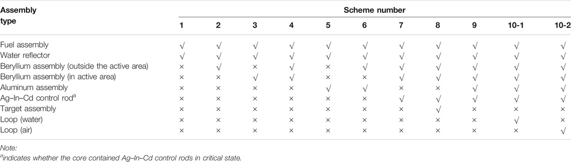
TABLE 1. Assembly type design in the experiment schemes.
Considering the critical experiment operation process, the control rod position in each experiment scheme should be kept as fixed as possible to simplify the experiment process. However, in the design it was found that the size of the active area in each experiment scheme was quite different, and the single control rod position and grouping design could not meet the reactivity control requirements.
According to the calculation and analysis, the control rod arrangement and grouping of all schemes were divided into three categories: the first type is shown in Figure 1, which was applicable to Scheme 1; the second type is shown in Figure 2, which was applicable to Schemes 2–6; and the third type is shown in Figure 3, which was applicable to Scheme 7∼Scheme 10-2.
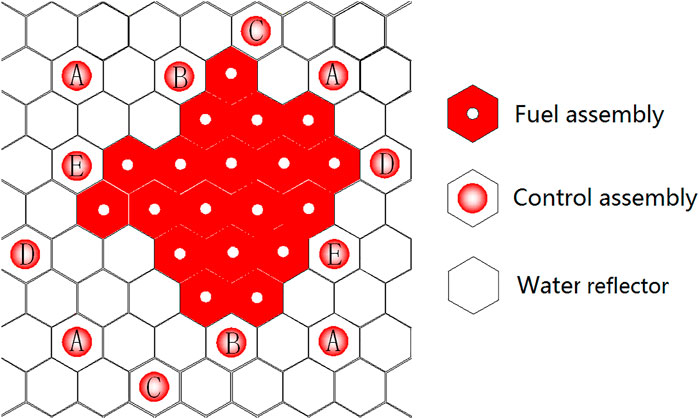
FIGURE 1. Layout of core and control rods in Scheme 1 (layout and grouping of type 1 control rods).
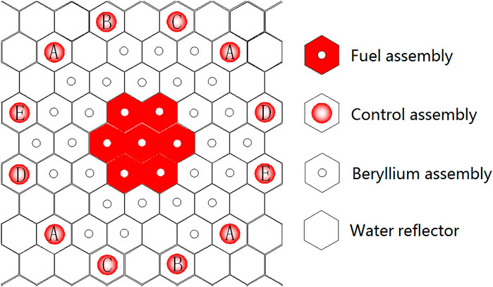
FIGURE 2. Layout of core and control rods in Scheme 2 (layout and grouping of type 2 control rods).
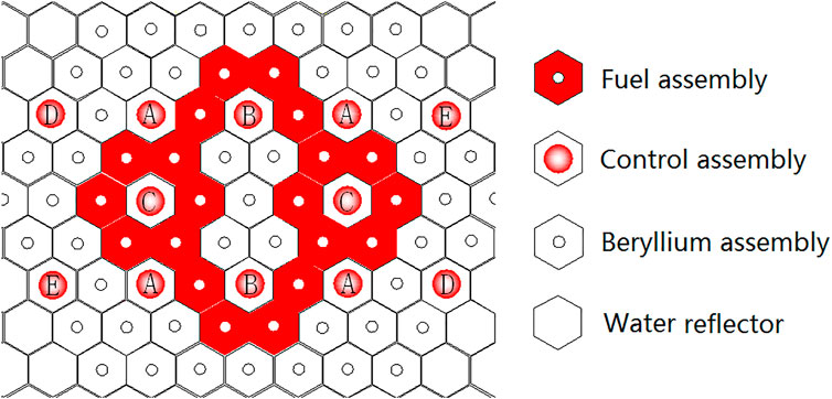
FIGURE 3. Layout of core and control rods in Scheme 7 (layout and grouping of type 3 control rods).
In Scheme 1, the core only contained fuel assemblies and the water reflector, and the active area of the core was smallest in size. If the second type control rod arrangement and grouping were arranged in Scheme 1, the value of rods would be too small to play the role of critical safety supervision. Scheme 2∼Scheme 6 adopted the second type control rod arrangement and grouping to meet the reactivity control requirements. The sizes of the core active area in Scheme 7∼Scheme 10-2 were further increased, and the arrangement and grouping of control rods of the first and second types could no longer meet the reactivity control requirements. Therefore, all critical experiment schemes were divided into the above three categories, which not only simplified the arrangement and grouping of control rods but also met the reactivity control requirements of each experiment scheme.
Figure 1 shows the core layout and control rod grouping in Scheme 1. The core contained fuel assemblies and water reflectors. There were 12 control rod assemblies in the core, which were divided into five groups, A∼E. There were four safety rods in the A rod group and two rods in the B, C, D, and E rod groups.
In this test, 19 fuel assemblies were loaded, and the keff of all control rods out was 1.0016. The fuel assemblies could be adjusted when the calculation deviated from the actual situation. By adjusting the position of the fuel assemblies radially and increasing or decreasing fuel assemblies, the keff of the core could be increased or decreased, thus making the core critical.
Figure 2 shows the core arrangement and control rod grouping in Scheme 2. The core contained fuel assemblies, beryllium assemblies (outside the active area) and water reflector. There were 12 control rod assemblies in the core, the positions of which were different from those in Scheme 1, but the grouping situation were the same.
In this test, 7 fuel assemblies and 27 beryllium assemblies were loaded, and the keff of all control rods out was 1.0002. When the calculation deviated from the actual situation, the beryllium assemblies could be adjusted. By adjusting the position of beryllium assemblies radially and increasing or decreasing beryllium assemblies, the keff of the core could be increased or decreased, thus making the core critical.
Figure 4 shows the core arrangement of Scheme 3. The core contained fuel assemblies, beryllium assemblies (in the active area), and water reflector. The arrangement of control rod assemblies in the core was the same as Scheme 2.
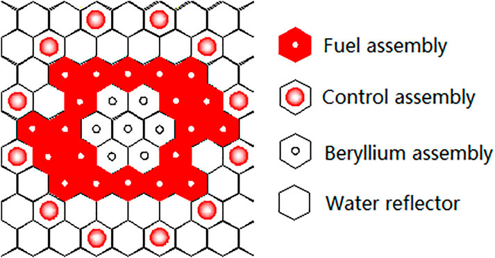
FIGURE 4. Core arrangement of Scheme 3.
In this test, 20 fuel assemblies and 7 beryllium assemblies were loaded, and the keff of the full lifting rod was 1.0003. When the calculation deviated from the actual value, the assemblies could be adjusted. By adjusting the position of the fuel assemblies radially, the keff of the core could be increased or decreased, thus making the core critical.
Figure 5 shows the core arrangement of Scheme 4. The core contained fuel assemblies, beryllium assemblies (inside the active area), beryllium assemblies (outside the active area), and water reflector. The arrangement of control rod assemblies in the core was the same as that of Scheme 2.
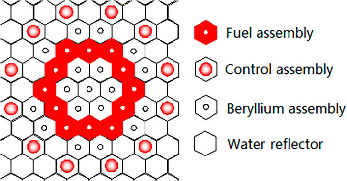
FIGURE 5. Core arrangement of Scheme 4.
In this test, 12 fuel assemblies and 18 beryllium assemblies (including 7 beryllium assemblies in the active area) were loaded, and the keff of all control rods out was 1.0031. When the calculation deviated from the actual situation, the beryllium assemblies could be adjusted. By adjusting the position of beryllium assemblies radially and increasing or decreasing beryllium assemblies, the keff of the core could be increased or decreased, thus making the core critical.
Figure 6 shows the core arrangement of Scheme 5. The core contained fuel assemblies, aluminum assemblies, and water reflector. The arrangement of control rod assemblies in the core was the same as that of Scheme 2.
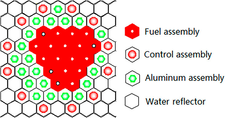
FIGURE 6. Core arrangement of Scheme 5.
In this test, 18 fuel assemblies and 21 aluminum assemblies were loaded, and the keff of all control rods out was 1.0000. When there was a deviation between calculation and practice, the core keff could be increased or decreased by adjusting the position of fuel assemblies and aluminum assemblies radially, increasing or decreasing aluminum assemblies and fuel assemblies, thus making the core critical.
Figure 7 shows the core arrangement of Scheme 6. The core contained fuel assemblies, beryllium assemblies, aluminum assemblies, and water reflector. The arrangement of control rod assemblies in the core was the same as that of Scheme 2.
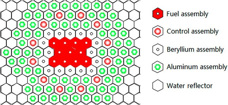
FIGURE 7. Core arrangement of Scheme 6.
In this test, 11 fuel assemblies, 16 beryllium assemblies, and 72 aluminum assemblies were loaded, and the keff of all control rods out was 1.0015. When there was a deviation between calculation and practice, the keff of the core could be increased or decreased by adjusting the position of aluminum and beryllium assemblies radially, increasing or decreasing aluminum and beryllium assemblies, thus making the core critical.
Figure 3 shows the core layout and control rod grouping in Scheme 7. The core contained fuel assemblies, beryllium assemblies (inside the active area), beryllium assemblies (outside the active area), water reflector, and Ag–In–Cd control rods. There were 12 control rod assemblies in the core, which were divided into five groups A∼E. There were four safety rods in the A rod group and two rods in the B, C, D, and E rod groups.
In this test, 20 fuel assemblies and 47 beryllium assemblies were loaded, among which 5 beryllium assemblies were loaded in the active area. The keff of all control rods in was 0.8451, and that of all control rods out was 1.2226. Scheme 7 would measure the critical rod position, control rod value, and shutdown depth.
Figure 8 shows the core arrangement of scheme 8. The core contained fuel assemblies, beryllium assemblies (inside the active area), beryllium assemblies (outside the active area), water reflector, Ag–In–Cd control rods, and target assemblies. The arrangement of control rod assemblies in the core was the same as that of Scheme 7.
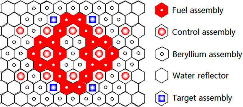
FIGURE 8. Core arrangement of Scheme 8.
This test was loaded with 20 fuel assemblies, 43 beryllium assemblies (including 5 beryllium assemblies in the active area), and 4 target assemblies. The keff of all control rods in was 0.8026, and that of all control rods out was 1.1352. Scheme 8 would measure the critical rod position, control rod value, and shutdown depth.
Figure 9 shows the core arrangement of scheme 9. The core contained fuel assemblies, beryllium assemblies, aluminum assemblies, water reflector, and Ag–In–Cd control rod assemblies. The arrangement of control rod assemblies in the core was the same as that of Scheme 7.
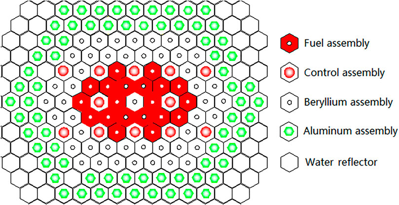
FIGURE 9. Core arrangement of Scheme 9.
This test was loaded with 20 fuel assemblies, 47 beryllium assemblies (including 1 beryllium assembly in the active area), and 71 aluminum assemblies. The keff of all control rods in was 0.8836, and that of all control rods out was 1.2137. Scheme 9 would measure the critical rod position, control rod value, and shutdown depth.
Figure 10 shows the core layout of Scheme 10-1. The core contained fuel assemblies, beryllium assemblies, aluminum assemblies, water reflector, Ag–In–Cd control rod assemblies, and irradiate holes, and the irradiate holes were filled with water. The arrangement of control rod assemblies in the core was the same as that of Scheme 7.
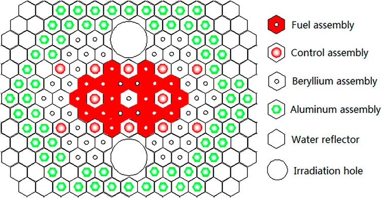
FIGURE 10. Core arrangement of Scheme 10-1 and Scheme 10-2.
This test was loaded with 20 fuel assemblies, 37 beryllium assemblies (including 1 beryllium assembly in the active area) and 67 aluminum assemblies. The keff of all control rods in was 0.8684, and that of the full lifting rod was 1.1808. Scheme 10-1 would measure the critical rod position, control rod value, and shutdown depth.
Scheme 10-2 had the same core layout as Scheme 10-1, with the only difference being that the irradiate holes were filled with air.
The keff of all control rods in was 0.8721, and that of the full lifting rod was 1.1878. Scheme 10-2 would measure the critical rod position, control rod value, and shutdown depth.
During the critical physical experiment, it was found that full height differential and integral value measurement of some control rods could not be carried out because the loading schemes had large excess reactivity. According to the specific situation, two schemes of critical rod position measurement with less excess reactivity were supplemented by reducing the number of assemblies of Scheme 9 and Scheme 10-1, which were named as Scheme 9A and Scheme 10A.
Figure 11 shows the core arrangement of Scheme 9A. The core contained 16 fuel assemblies, 25 beryllium assemblies (including 1 beryllium assembly in the active area), and 71 aluminum assemblies. The keff of all control rods in was 0.8118, and that of all control rods out was 1.0955. Scheme 9A would measure the critical rod position, control rod value, and shutdown depth.
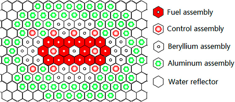
FIGURE 11. Core arrangement of Scheme 9A.
Figure 12 shows the core arrangement of Scheme 10A. The core contained 16 fuel assemblies, 25 beryllium assemblies (including 1 beryllium assembly in the active area), and 60 aluminum assemblies. The keff of all control rods in was 0.8055, and that of all control rods out was 1.0920. Scheme 10A would measure the critical rod position, control rod value, and shutdown depth.
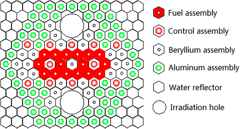
FIGURE 12. Core arrangement of Scheme 10A.
Table 2 shows the verification calculation results of core keff for critical mass measurement schemes. It could be seen that the deviation of verification calculation in Scheme 1 is only 0.3%, which is in good agreement with the experimental result, which indicates that the nuclear design code has high accuracy in calculating the core of pure fuel assemblies. The calculation deviations of Schemes 2∼4 are all within 0.8%, and they are all negative deviations, which indicates that the nuclear design code has higher accuracy in calculating the cores containing beryllium assemblies. Scheme 5 used fuel assemblies and aluminum assemblies, and the core keff calculation deviation is small and positive, which indicates that the aluminum assembly calculation model has high calculation accuracy. Scheme 6 used fuel assemblies, beryllium assemblies, and a large number of aluminum assemblies, and the core keff calculation deviation is negative and the absolute value is about 1.0%, which still can be accepted.
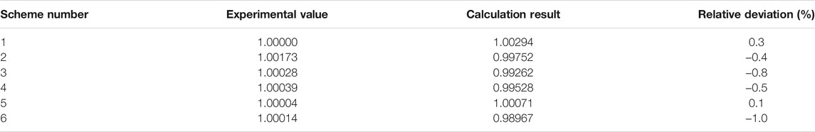
TABLE 2. keff verification calculation results of critical mass measurement test.
Table 3 shows keff verification calculation results of the core critical rod position. It could be seen that the calculation deviations of Scheme 7∼Scheme 10 are within ±0.8%, which are in good agreement with the test results and indicate that the nuclear design code has high accuracy in calculating the critical rod positions of various core layout schemes.
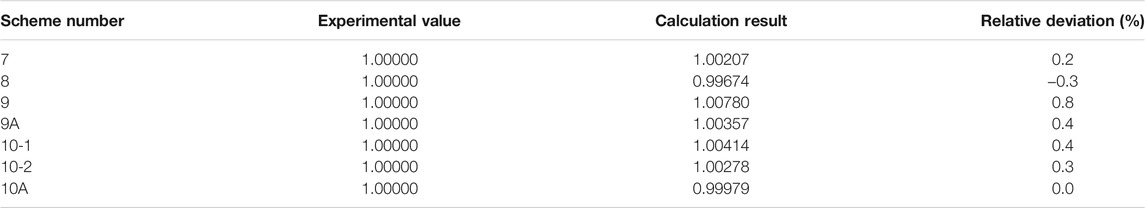
TABLE 3. keff verification calculation results of core critical rod position.
Table 4 shows the calculation results of the cold integral value of single control rod and rod groups with different schemes. It can be seen that the calibration deviation of the control rod integral value is within 20% except for B2 rod and B rod groups in Scheme 10A.
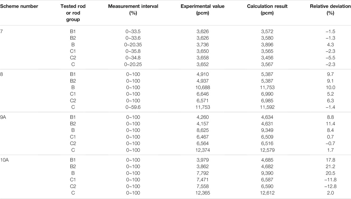
TABLE 4. Calculation results of integral value of control rods.
Figures 13–15 and Supplementary Figures S1–S3 show the cold differential value curves of different rod groups with different schemes. It can be seen that the calculated values of differential value curves of control rods in other cases are in good agreement with the experimental values except for the calculated values in Scheme 8.
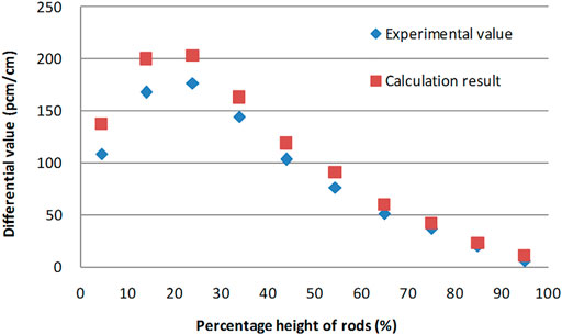
FIGURE 13. Differential value curve of B rod group (Scheme 8).
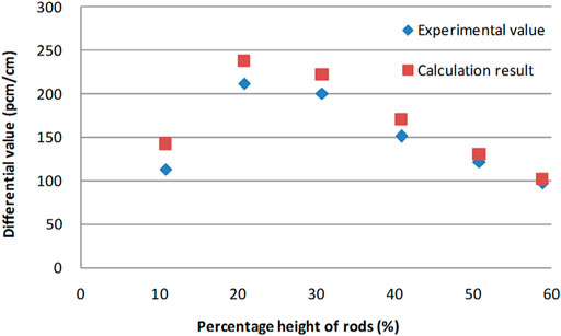
FIGURE 14. Differential value curve of C rod group (Scheme 8).
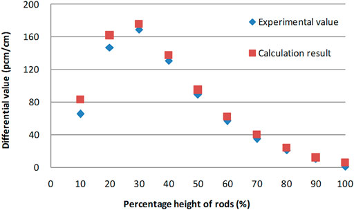
FIGURE 15. Differential value curve of B rod group (Scheme 9A).
Table 5 shows the calculation results of cold shutdown depth of each scheme. It can be seen that the calculated deviations of all schemes are within 20%, which is in good agreement with the experimental values.
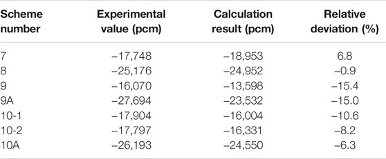
TABLE 5. Calculation results of shutdown depth.
Based on the requirement of the core critical physical experiment of HCTFR, 11 core critical physical experiment schemes and 2 supplemental schemes were proposed to validate the calculation accuracy and reliability of the nuclear design code CPLEV2. According to the critical physical experiment data, the reactivity calculation deviations of all critical rod position measurement schemes are within ±1.0%. The validation results show that the nuclear design code CPLEV2 has high calculation accuracy and reliability for the core of hexagonal casing type fuel and it can be used for HCTFR nuclear design.
The original contributions presented in the study are included in the article/Supplementary Material; further inquiries can be directed to the corresponding author.
WL: conceptualization, methodology, and software. WY: methodology, visualization, and investigation. LL: methodology, visualization, and investigation. HS: investigation, funding acquisition, and supervision.
The authors declare that the research was conducted in the absence of any commercial or financial relationships that could be construed as a potential conflict of interest.
All claims expressed in this article are solely those of the authors and do not necessarily represent those of their affiliated organizations, or those of the publisher, the editors, and the reviewers. Any product that may be evaluated in this article, or claim that may be made by its manufacturer, is not guaranteed or endorsed by the publisher.
The Supplementary Material for this article can be found online at: https://www.frontiersin.org/articles/10.3389/fenrg.2021.764897/full#supplementary-material
Supplementary Figure S1 | Differential value curve of C rod group (scheme 9A).
Supplementary Figure S2 | Differential value curve of B rod group (scheme 10A).
Supplementary Figure S3 | Differential value curve of C rod group (scheme 10A).
Liu, J., Yao, D., Zeng, D., and Wang, Y. (2000). Low-enriched Core Nuclear Design of HFETR, Compilation of Literatures on the Twenty –Year Operation of HFETR (1980-2000). Shanghai: Nuclear Power Institute of China.
Tang, X., Wang, G., and Wu, Q. (2011). The Zero Power Physical Experiment of the HFETR LEU Core, Compilation of Literatures on the Thirty –Year Operation of HFETR (1980-2010). Shanghai: Nuclear Power Institute of China.
Xie, Z. (1994). Physical Analysis of Nuclear Reactor Property [M]. Beijing: Atomic Energy Press, 68–71.
Keywords: hexagonal casing type fuel reactor (HCTFR), critical physical experiment, nuclear design code, experiment schemes, code validation
Citation: Lianjie W, Yanqin W, Lei L and Shien H (2021) Scheme Design and Data Analysis of Critical Physical Experiment for Hexagonal Casing Type Fuel Reactor. Front. Energy Res. 9:764897. doi: 10.3389/fenrg.2021.764897
Received: 26 August 2021; Accepted: 05 November 2021;
Published: 08 December 2021.
Edited by:
Tengfei Zhang, Shanghai Jiao Tong University, ChinaReviewed by:
Xiang Wang, Harbin Engineering University, ChinaCopyright © 2021 Lianjie, Yanqin, Lei and Shien. This is an open-access article distributed under the terms of the Creative Commons Attribution License (CC BY). The use, distribution or reproduction in other forums is permitted, provided the original author(s) and the copyright owner(s) are credited and that the original publication in this journal is cited, in accordance with accepted academic practice. No use, distribution or reproduction is permitted which does not comply with these terms.
*Correspondence: Wang Lianjie, bWNkMjI2NEAxMjYuY29t
Disclaimer: All claims expressed in this article are solely those of the authors and do not necessarily represent those of their affiliated organizations, or those of the publisher, the editors and the reviewers. Any product that may be evaluated in this article or claim that may be made by its manufacturer is not guaranteed or endorsed by the publisher.
Research integrity at Frontiers
Learn more about the work of our research integrity team to safeguard the quality of each article we publish.