- 1Sino-French Institute of Nuclear Engineering and Technology, Sun Yat-Sen University, Zhuhai, China
- 2Disease Prevention Department, The Second Hospital Affiliated to Heilongjiang University of Chinese Medicine, Harbin, China
- 3College of Petroleum Engineering, Liaoning Shihua University, Fushun, China
Mechanical seals prevents flow leakages in reactor coolant pumps thus playing an important role in their operational safety. However, their operational performance depends on different parameters, the seal geometrical design and the sealing medium characteristics among others. This study investigates the main performances of the waviness end-face mechanical seal, considering the effect of fluid flow and thermal characteristics. The involved coupled thermal-hydraulic process is simulated using the OpenFOAM, based on the coupled Navier-Stokes and energy balance equations. Study results showed that the viscosity-temperature effect may increase the flow leakage, and decrease both the opening force and the liquid film stiffness. The later may be decreased to negative values under specific conditions. It’s therefore generally found that visco-thermal characteristics of the sealing medium may negatively affect mechanical seal’s operational stability. On the other hand, from the perspective of liquid film temperature rise, the visco-thermal effect may lead to the regulation of the temperature rise in the liquid film, which improves the mechanical seal’s operational safety in some aspects. Through a comprehensive analysis, the optimal structural parameters of the waviness mechanical seal investigated in this study are found to be hi = 2.5μm, β = 900μrad (Rd-Ri)/(Ro-Ri) = 0.2, α = 0.8, and k = 9.
Introduction
The shaft seal is an isolation device to prevent the leakage of reactor coolant pumps (RCP) (Salant et al., 2018), which is directly related to the safe operation of the nuclear power plant (Nilsson et al., 2009; Baraldi et al., 2011; Feng et al., 2016; Kok and Benli, 2017; Luqman et al., 2019). As one of the key components of shaft seals, the mechanical seal (Harp and Salant, 1998; Clark et al., 2002; Simon, 2018) plays a vital role in the safety and reliability of the entire structure, where different shapes of its end face lead to the different hydraulic effects (hydrodynamic and hydrostatic effects). In comparison with the hydrostatic seals, hydrodynamic seals can reach better performance owing to its hydrodynamic effect (Pascovici and Etsion, 1992; Batten et al., 2008).
Many researches on hydrodynamic seal’s structure and operational mechanism have been conducted in the past decades (Stanghan‐Batch and Iny, 1973; Wen et al., 2013; Falaleev, 2015; Han and Tan, 2020). Among others, in order to analyze the pressure and temperature distribution within a mechanical seal, Merati et al. (1999) established a computational model for flow and thermal analysis, which could effectively predict both the flow field characteristics in the seal chamber and the temperature distribution within the stator. On the other hand, wanting to improve the performance of a mechanical seal, Clark et al. (2002) established a coupled thermal-hydraulic model based on the CFD method. Based on the associated model, they proposed some effective measures to improve the cooling effect of the stationary ring’s end faces. In the same respect, Danos et al. (2000) established a numerical model for thermo-hydrodynamic lubrication, involving heat transfer analysis through the rings. This model tackled a three-dimensional general case of misaligned faces and a wavy rotor face in a stable dynamic tracking regime. The results showed the influence of different parameters such as the interface geometry, the nature of the lubricant, the fluid flow, the ring materials, and heat transfer conditions on the ring surfaces. Tournerie et al. (2001), analyzing the mechanical seal’s thermal behavior, investigated the influence of mechanical seal end-face tilt, where they built a three-dimensional thermal-hydraulic coupling model to study the temperature distribution of the seal ring liquid film, as well as the heat transfer process between seals.
In some cases, complicated conditions should be considered, especially in the special pump types. To say the least, wanting to analyze the applicability of the wave-tilt dam seal, Young et al. (Young and Lebeck, 1989; Young et al., 2003) experimentally studied the characteristics of the wave-tilt dam seal, in which both the hydrostatic and hydrodynamic effects are produced on the radial taper and circumferential waves of the seal, respectively. Due to these properties, this seal can provide sufficient opening force and can be used under complex conditions. In addition to the wave-tilt dam seal, Mayer (Mayer, 1989) proposed a mechanical seal with a deep groove structure on the sealing end face. During this research, the experiment of the end-face mechanical seal of the rectangular deep-buried water cushion body is mainly considered, and its mathematical model for the elastic flow is established using the relaxation iteration method. It was shown that the pressure effect would lead to the wave deformation of the hydropads seal. Djamaï et al. (2010) put forward a numerical model of thermal-fluid analysis in deep groove seal, and the influences of operation and design parameters on sealing performance were analyzed. It was shown that the hydrodynamic effect of the deep groove seal was negligible, while the opening force was mainly provided by the hydrostatic effect.
In addition to the thermal-hydraulic properties, another important property that should be focused on is the thermos-elastic property, which in addition to thermal characteristics, describes the elastic characteristics in the sealing mechanism. To this end, some improved research works involving thermo-elastic properties coupling have been conducted. Among others, Liu et al. (2011); Liu et al. (2015) with a target of studying the sealing mechanism of the wave-tilt dam end-face mechanical seal under different working conditions, established a three-dimensional thermo-elastic coupling model and analyzed the sealing mechanism of the mechanical seal under the starting and stable operating conditions. Peng et al. (2012) established a coupled thermal-fluid-solid model for a convergent double tapered hydrostatic mechanical seal and experimentally investigated the effect of thermo-elastic deformation on the seal performance. Among other parametric studies, Hu et al. (Chandramoorthy, Hadjiconstantinou) studied the effect of speed and closing pressure on the sealing behavior for a grooved end-face seal ring, where the increase of both parameters led to a correspondingly increasing volume leakage rate. As for Gustafsson et al. (2017), the shape of micro-grooves on the end-face of the sealing ring may considerable influence the thermohydrodynamic characterstics of the liquid film in its seal gap region.
Taking from the above presented literature and other works from different sources, it’s obvious that previously conducted works have systematically established the analytical method to study mechanical seal operations. Most of the previous works on mechanical seals are mainly based on the bearing lubrication theory, in which the Reynolds equation (Chandramoorthy, Hadjiconstantinou; Gustafsson et al., 2017) is often used as the governing equation to solve the pressure distribution of the liquid film in the seal ring gap. The Reynolds equation is a simplified approximation of the Navier-Stokes equation (Temam, 2001; Pietarila Graham et al., 2008; Sinchev et al., 2018; Danchin and Mucha, 2019) to solve the narrow gap laminar flow. In this approximation, the pressure change along the film thickness direction is neglected by assuming that the thickness of the seal ring gap liquid film is small enough. However, for the complicated mechanical seal conditions (e.g., the wave-tilt dam end-face mechanical seal), the pressure change along the film thickness direction should be considered for more reliable results. When neglecting this pressure change, some errors will be introduced and the numerical solutions may deviate from the real life conditions. This situation requires more accurate equations to describe the fluid flow and heat transfer phenomenon in the mechanical seal. To this end, the Navier-Stokes equations, being a more detailed description than the Reynolds equation, can be considered. Therefore, in the present study, in order to study the waviness end-face mechanical seal more accurately, the coupled Navier-Stokes and Energy equations are used based on the open-source software OpenFOAM to analyze the pressure and temperature distributions (Jasak et al., 2007; Gebreslassie et al., 2013a; Gebreslassie et al., 2013b; Chen et al., 2014). The viscosity-temperature effect (visco-thermal effect) of the sealing medium is also considered to calculate the heat-flow coupling process. Based on this model, the influences of structural parameters on seal performance are studied, and the optimal parameters of the seal design are proposed.
The present article is organized as follows. In Research Object and Methodology, both the investigated case and the utilized research methodology are established and explained. This includes the seal geometric model, sealed medium governing equations, the utilized boundary conditions, and the definitions of main sealing performance variables. Results and Discussion studies the effects of structural parameters on the sealing performances, including the leakage rate, the film opening force, the film stiffness, and the temperature distribution. The main conclusions of this work are given in Conclusion.
Research Object and Methodology
Geometric Model
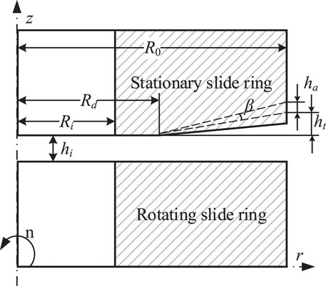
The geometry of the investigated mechanical seal in the RCP is shown in Figure 1. It consists of two sliding rings, namely the rotating ring and stationary ring. The inside and outside radius of the seal face are set as Ri = 140.25 mm and Ro = 151.25 mm, respectively. The rotating slide ring rotates counterclockwise at an angular speed of w. Between the rotating and stationary slide rings, the sealed medium (deionizer water is used in this case) flows from the outside zone to the inside chamber via the main leakage path with thickness hi.
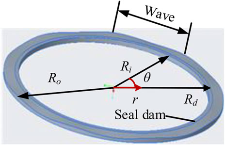
The end face of the rotating slide ring is flat, and its roughness is less than 1 μm. The end face of the stationary slide ring consists of 9 wavinesses and a flat plane, as shown in Figure 2. The film thickness between the frictional pair is described as in Eq. 1 (Liu et al., 2011):
where hi, β, r, and θ stand for the thickness of the inner radius, radial angle on the stator face, and the coordinate of radial and rotating directions, respectively. Moreover, Ri, Rd, and Ro are the inner radius, dam radius, and outer radius, respectively. The dimensionless parameter α is defined as shown in Eq. 2:
ha and ht stand for the wave amplitude and taper height of the outer radius; k is the wave number.
Governing Equations
The coupled thermal-hydraulic behavior within the mechanical seal is analyzed using the numerical technique, which starts from the establishment of the governing equations. To simplify the numerical simulation, some basic and reasonable assumptions are applied as follows:
1) The sealed fluid is incompressible since the flow velocity is very small; and the viscosity-temperature effect is considered.
2) Only the steady-state condition under the normal operations is considered, and the seal faces are always parallel to each other.
3) According to the relevant parameters, the Re number is about 210 and the flow factor number is 0.354. Therefore, the fluid film is laminar.
4) The pressure variation in the direction of the fluid film is considered.
5) The cavitation phenomenon is neglected.
6) The seal gap is considered as full-film lubrication, and no face contact happens during the operation.
Under these conditions, the governing equations to describe the lubrication film flow are written as:
where u is the fluid velocity, ρ is the density of deionized water, p is the pressure, and ν is the kinematic viscosity.
Due to the very narrow seal gap, the large frictional heat will be produced by viscosity shear force in the process of operation, which will increase the temperature of the fluid film. Therefore, to simulate the temperature field, the energy equation including the dissipation item should be considered as in Eq. 5 (Shen et al., 2019):
where Φ is the dissipation function, and is defined as shown in Eq. 6:
In this equation, μ is the dynamic viscosity while u, v, and w are the components of fluid velocity u along with the directions of x, y, and z coordinates. When considering the viscosity-temperature effect, the viscosity is strictly dependent on the temperature distribution of the fluid film as shown in Eq. 7:
where T0 is the reference temperature and μ0 is the reference viscosity, β0 is the parameter that indicates the influence of temperature change on viscosity, namely the viscosity-temperature coefficient.
In this study, the initial operating parameters are kept constant: the viscosity-temperature coefficient keeps β0 keeps the value of 0.0175 K−1; the reference temperature keeps T0 stays 323.15K; and the reference viscosity keeps μ0 stays 0.05494 × 10⁻³ Pa·s.
Boundary Conditions
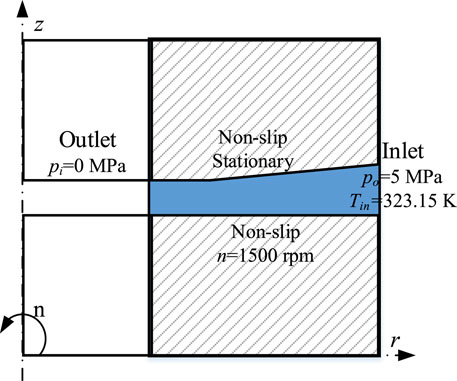
The fluid region (blur region) is the area enclosed by the inner and outer boundaries (r = Ri, and r = Ro) and the upper and lower sealing surfaces, as shown in Figure 1. To simulate the behavior of the proposed seal numerically, the boundary conditions should be determined.
The schematic of the boundary conditions is shown in Figure 3. For simplification, one of the waviness widths in the circumferential direction is taken, and the periodic cyclic boundaries are applied to the circumferential boundaries, i.e., the front and back boundaries. The considered mechanical seal is an external pressure structure. During the normal operation, the working fluid flows from the external high-pressure side to the internal low-pressure side, i.e., the outer boundary (r = Ro) is the inlet pressure boundary with po = 5 MPa, and the inner boundary (r = Ri) is the outlet pressure boundary with pi = 0 MPa. Since there is no slip between the boundary fluid and the sealing surface of the stationary slide ring, the no-slip boundary condition is applied to up and bottom boundaries (i.e., the upper and lower seal surfaces). The rotating speed of the sealing surface of the rotating slide ring is n = 1,500 rpm. The temperature boundary is applied to the inlet boundary, in which the inlet temperature is set as Tin = 323.15 K. The zero-gradient boundary of heat transfer is applied to the outlet, up, and bottom boundaries. The tolerance of all the simulations is set as 10−6.
Sealing Performance
To study the characteristics of the waviness end-face mechanical seal in reactor coolant pumps with the viscosity-temperature effect, some typical and concerned parameters are analyzed, including the leakage rate Q, the opening force Fopen and the liquid film stiffness kz. The leakage rate is one of the main parameters to ensure the safe and stable operation, which is defined as:
where Vr is the fluid velocity in the radial direction defined as:
The appropriate leakage rate is important to ensure stable and safe operation. On the one hand, too low leakage may lead to the direct wear of seal ring end face, and on the other hand, the excessive leakage may cause seal failure.
Similarly, another important parameter, namely sealing opening force that characterizes the bearing capacity of the liquid film can be obtained by integrating the liquid film pressure along the sealing end face as:
Near the steady-state equilibrium position of the liquid film, the increase of opening force caused by a slight axial disturbance is the liquid film stiffness, which can be defined as:
Results and Discussion
This section analyzes the influences of the structural parameters on sealing performance considering the viscosity-temperature effect. The effects of thermo-hydrodynamic lubrication (THD) and hydrodynamic lubrication (HD) are compared and analyzed, and the optimal design parameters of the waviness mechanical seal are obtained.
Effects of Structural Parameters on the Leakage Rate
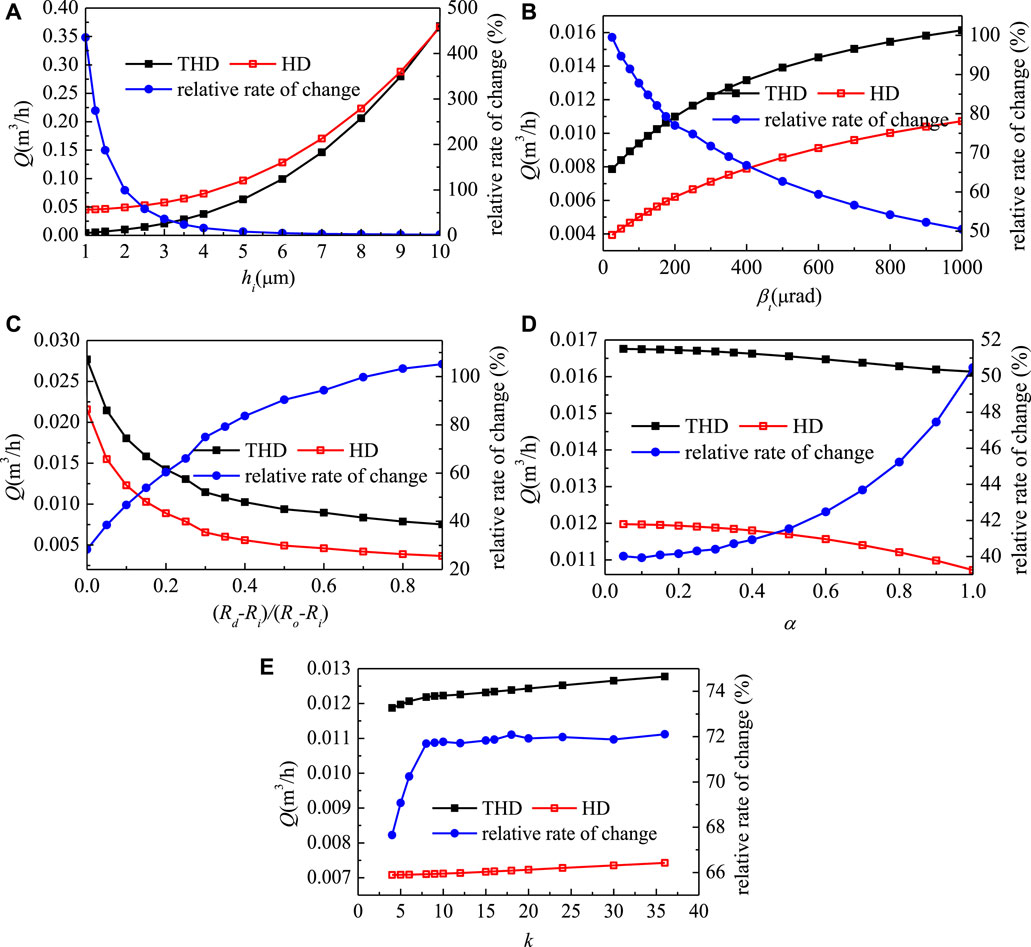
Due to the small sealing clearance, when the sealing ring rotates at high speed, the viscous shear friction heat will be generated, which reduces the viscosity and correspondingly, reduces the leakage. Figure 4 shows the effects of the structural parameters of the waviness end-face mechanical seal on the leakage rate when considering the viscosity-temperature effect. The effect of film thickness on the leakage is shown in Figure 4A, in which the relative rate of change is the relative deviations of the HD solutions from the THD solutions. In general, as the film thickness increases, the leakage rates obtained from the THD and HD processes gradually close to each other, since that, as the film thickness increases, the viscous shear friction heat effect decreases correspondingly. When the film thickness is small enough, the HD process will strongly overestimate the leakage rate, while when the film thickness reaching 10 μm, the HD solution is much closed to the THD solution and the relative change rate decreases to 1.75%. These conditions indicate that the viscosity-temperature effect will be obvious when the liquid film is thin and will decrease as the thickness of the liquid film increases. Therefore, from this point of view, the film thickness should be large enough to ensure small viscosity-temperature. However, if the base film is too thick, the leakage will increase and the sealing effect will not be achieved. Therefore, the base film thickness of the seal design should be kept within the appropriate range.
Figure 4B shows the effect of the taper of the stationary slide ring end-face on the leakage. Similar to that of the base film thickness, as the taper increases, the viscosity-temperature effect on the leakage rate decreases. As the taper increases, the film thickness of the taper zone in the seal clearance increases, and the viscous shear friction heat decreases correspondingly. Considering the viscosity-temperature effect, the relative change rate of the leakage decreases from the maximum of 99.49–50.47% with the increase of the taper, which indicates that the taper should be large enough to reduce the viscosity-temperature effect.
Figure 4C shows the effect of the dam width ratio (Rd-Ri)/(Ro-Ri) on the leakage rate. Different from the film thickness and the taper, the leakage rate decreases as the dam width ratio increases, and the relative change rate increases correspondingly. The increase of the dam width ratio directly increases the dam area, which increases the viscous shear friction heat and the temperature rise in the liquid film. Due to this effect, the viscosity-temperature effect of the dam width ratio will increase as the dam-width ration increases. As the dam width ratio increases, the relative change rate of leakage will increase from the minimum 28.27% to the maximum 105.19%. Therefore, to reduce the viscosity-temperature effect, a relatively lower dam width ratio is required.
Figure 4D shows the effect of the dimensionless parameter α on the leakage rate, i.e., the effect of waviness amplitude of stationary slide ring end-face on the leakage rate. The increase of α means the increase of the waviness amplitude, which will reduce the film thickness of the waviness region, and increase the viscous shear friction heat. Therefore, with α increasing, the effect of viscosity-temperature on the leakage increases correspondingly. On the other hand, the decrease in film thickness is still limited due to the increase of waviness amplitude. Therefore, from the point of the relative change rate variation, it does not change much, which varies between 40.02 and 50.17%. However, from the point of the relative change rate value, the viscosity-temperature effect is still large. Figure 4E shows the effect of the wave number on the leakage rate. In general, the variation of wavenumber has little effect on the relative change rate of leakage. The relative change rate of leakage remains between 67.66 and 72.1%.
Effects of Structural Parameters on the Film Opening Force
This part analyzes the influence of the viscosity-temperature effect on the opening force. As the temperature increase, the fluid viscosity will decrease and the viscosity-temperature effect for the waviness end-face mechanical seal will be reduced correspondingly. Meanwhile, the hydrodynamic effect and the hydrostatic effect will be reduced. Therefore, the opening force considering the viscosity-temperature effect (THD solutions) will be less than that without considering the viscosity-temperature effect (HD solutions). Figure 5 shows the effects of different structural parameters on the opening force, the solutions with and without considering the viscosity-temperature effect are compared with each other. Different from the leakage, the relative change rate is always less than 0, i.e., the opening force with considering the viscosity-temperature effect is lower than that without considering the viscosity-temperature effect.
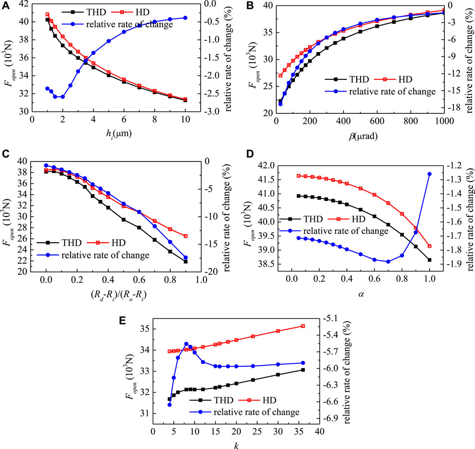
FIGURE 5. Effect of structural parameters on the opening force under the viscosity-temperature effect.
Figure 5A shows the effect of the base film thickness on the opening force. As the base film thickness increases, the opening force decreases and the relative change rate of the opening force increases first and then decreases. The relative change rate varies from −0.39 to −2.59%. As the base film thickness increases, viscous shear friction heat reduces and the viscosity-temperature effect has less effect on the opening force.
Figure 5B shows the effect of the taper of stationary slide ring end-face on the opening force, in which the opening force increases as the taper increases and the relative change rate decreases as the taper increases. As the taper increases, the film thickness in the waviness region increases and the viscous shear friction heat decreases. Therefore, the effect on the viscosity of the sealing medium reduces. The effect on the opening force and the relative change rate of the opening force will decrease with the increase of taper, which varies from −1.26 to −17.38%.
Figure 5C shows the effect of the dam width ratio on the opening force, in which the opening force decrease as the dam width ratio increases, while the relative change rate increases as the dam width ratio increases. With the increase of the dam width ratio, the dam area increases, the viscous shear friction heat increases, and the influence on the viscosity of the sealing medium increase correspondingly. The increase of the dam width ratio increases the influence of opening force, and the relative change rate of opening force increases from −0.72 to −17.41%.
Figure 5D shows the effect of α on the opening force, in which the opening force decreases as α increases, and the relative change increases first and then decreases. As α increases, the waviness amplitude increases, and the viscous shear friction heat increases, thus the viscosity change increase also. Therefore, with the increase of α, the influence of viscosity-temperature on the opening force increases. When α increases to a certain value, the hydrodynamic effect of the waviness end-face seal becomes strong enough, leading to a decrease in the relative change rate of opening force, from −1.26 to −1.88%.
Figure 5E shows the effect of the wave number on the stationary slide ring end-face on the opening force. The opening force increases as the wave number increases and the viscosity-temperature effect makes the opening force lower. The increase of wave number will make the high-temperature region denser, thus weakening the hydrostatic effect, and the opening force will be relatively small. However, the hydrodynamic effect will be enhanced as the wavenumber increases. The relative change rate of the opening force is not large, which varies between 5.56 and 6.65%.
Effects of Structural Parameters on Film Stiffness
This part studies the influence of structural parameters of the mechanical end-face seal on the fluid film stiffness with considering the viscosity-temperature effect. The film stiffness under different structural parameters is shown in Figure 6, with and without considering the viscosity-temperature effect, respectively. To analyze the effect of the viscosity-temperature effect on the fluid film stiffness, the relative change rate of the liquid film stiffness was calculated. The negative sign of the relative change rate indicates the decrease of film stiffness.
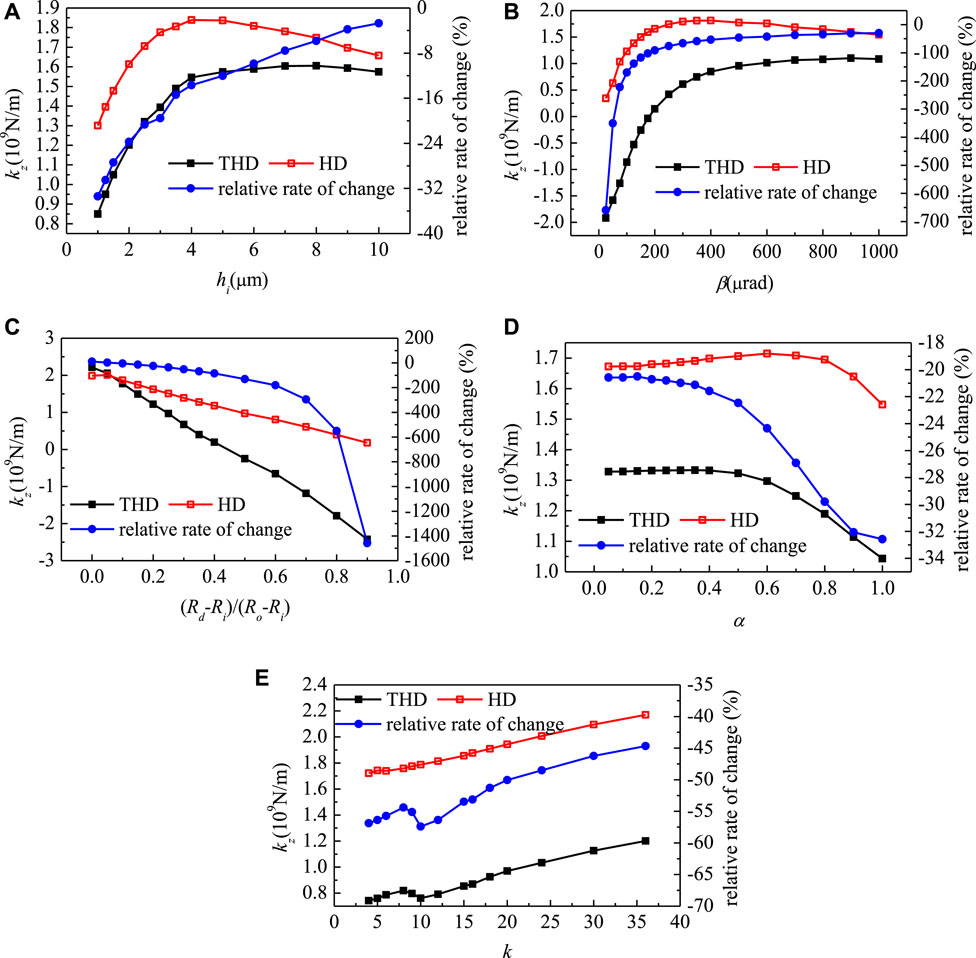
FIGURE 6. Effect of structural parameters on the fluid film stiffness under the viscosity-temperature effect.
Figure 6A shows the effect of film thickness on film stiffness. As the film thickness increases, the stiffness increases first and then decreases, while the relative change rate always decreases. In comparing to the HD results, the stiffness of the THD results is always lower than that of the HD results, due to the viscosity-temperature effect. With the increase of the film thickness, the relative change rate of the film stiffness decreases from −33.39 to −2.7%. This indicated that as the film thickness increases, the effect of the viscosity-temperature effect on liquid film stiffness will decrease. With the increase of the film thickness, the viscous shear friction heat and the weaker the viscosity-temperature effect will reduce.
Figure 6B illustrates the effect of the taper of stationary slide ring on the liquid film stiffness, in which both the film stiffness and the relative change rate increase first and then tend to stable. When considering the viscosity-temperature effect, the liquid film stiffness tends to be lower than that of the HD solutions. This effect will be decreased as the taper increases. As the taper degree decreases, the viscosity-temperature effect generates a more striking impact on the liquid film stiffness, and the liquid film stiffness can be negative, i.e., the opening force increases as h increases. This phenomenon is caused by the generated viscous shear friction heat, which could be very unfavorable for the stable operation of the seal if the taper angle is extremely small. Under the optimal circumstance with the largest taper degree, the relative rate of change can be as low as 44.67%, which could be much better for the stable operation. In consideration of this, credence should be given to a relatively larger taper degree when designing the mechanical seal.
Figure 6C depicts the effect of the dam width ratio on the fluid film stiffness. When the dam width ratio being equal to zero, there is no dam area and the viscosity-temperature effect will increase the liquid film stiffness. However, when the dam area exists, the viscosity-temperature effect, in turn, decreases the film stiffness. As the dam area increases, an increasing amount of viscous shear friction heat is generated, which leads to a non-negligible viscosity-temperature effect on the liquid film stiffness. According to Figure 6C, when the dam width ratio is large enough, the film stiffness without considering the viscosity-temperature effect is close to 0 and the film stiffness with considering the viscosity-temperature has a relative larger negative value. The relative change rate of the liquid film stiffness can reach a very large value, which will threaten the operation of the seal. As the dam width shrinks, the relative change rate of the liquid film stiffness can decline to 2.27%. The above result indicates the importance of the small dam width ratio in the design of the mechanical seal.
Figure 6D presents the effect of α on the liquid film stiffness. As α increases, both the stiffness and the relative change rate stabilize first and then decrease. From this picture, one can find that the viscosity-temperature effect will reduce the film stiffness. To be more specific, as α increases, the influence of the viscosity-temperature effect on the liquid film stiffness increases correspondingly. The relative change rate of the liquid film stiffness slightly increases from −20.57 to −32.57%.
Figure 6E shows the effect of the wave number on the liquid film stiffness, in which both the stiffness and relative change rate increase as the wavenumber increases. When considering the viscosity-temperature effect, the film stiffness will be reduced and the relative change rate in different wavenumber can reach 44.67–57.41%. The change of wave number will lead to a higher density of the high-temperature region in the liquid film. It is noteworthy that the changing wavenumber does not lead to a large temperature rise, thus the change of relative change rate is relatively gentle.
According to these analyses, the viscosity-temperature effect should be taken into consideration in analyzing the performance of the waviness end-face mechanical seal. The neglect of the viscosity-temperature effect will lead to the overestimation of the film stiffness, which will destroy the safe and stable operation of the seal. Besides, to control the leakage while ensuring the sufficient bearing capacity and stable operation, it is necessary to set appropriate structural parameters of the waviness end-face mechanical seal in the design. In this case, the mechanical seal with the base film thickness being kept at 2.5 μm, the taper being around 900 μrad, the dam width ratio being around 0.2, α being around 0.8, and the wave number being 9 can be one of the optimal combinations for the best performance.
Effects of Structural Parameters on Film Temperature Distribution
In the final part, the influence of the structural parameters of the waviness end-face mechanical seal on the temperature field of the liquid film is studied. When considering the viscosity-temperature effect, the viscosity of the working fluid decreases as the temperature increases. This property will reduce the generated viscous shear friction heat and suppresses the increase of temperature in turn. According to these characteristics, it can be predicted that the maximum temperature difference in the fluid film with considering the viscosity-temperature effect will be smaller than that without considering the viscosity-temperature effect.
Figure 7A illustrates the effect of the base film thickness on the maximum temperature difference in the liquid film, in which β = 300 μrad and α = 0.5. In general, as the base film thickness increases, the temperature increase in the fluid film becomes lower. In considering the viscosity-temperature effect, the temperature increases under different base file thicknesses when hi < 4 μm are always lower than that without considering the viscosity-temperature effect. When hi > 4 μm, the temperature increases of THD solutions and HD solutions are all the same, since the large film thickness makes the viscosity-temperature effect unobvious. Correspondingly, the relative change rate between THD and HD solutions decreases as the film thickness increases, which agrees with the regulation of temperature increases.
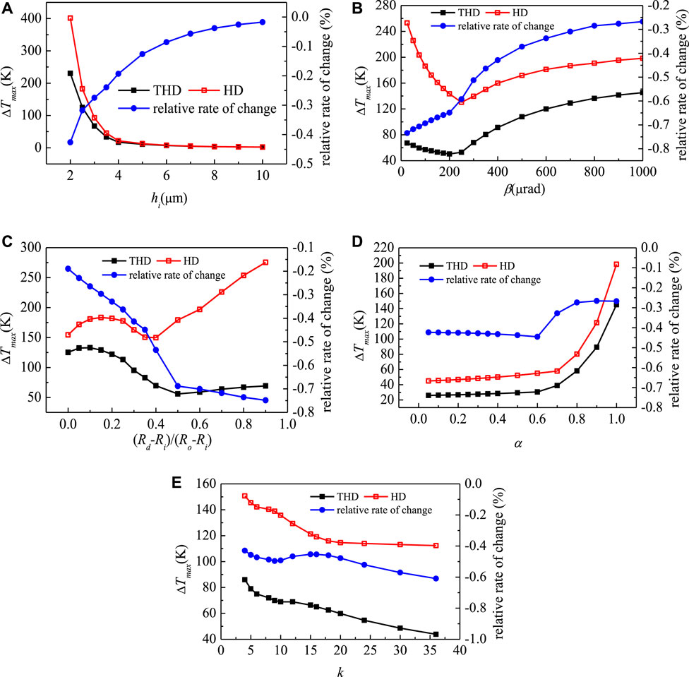
FIGURE 7. Effect of structural parameters under the viscosity-temperature effect on the maximum temperature difference in the liquid film.
Figure 7D depicts the effect of α on the maximum temperature difference in the liquid film at two stages. Under different α, the maximum temperature difference increases in different trends. When α < 0.6, the maximum temperature increases slowly, and after that, the temperature difference increases sharply. This condition is caused by the increase of α when α is big enough. At large α, the increase in α will cause a high temperature in the wave area of the outer diameter side, which results in a sharp increase in temperature difference. For the safe operation, this sharp increase should be avoided in designing the WTD mechanical seal, which requires that the value of α should be set no more than 0.8. The relative change rate between the THD and HD solutions slightly lowered, and always kept between 0.2–0.5%, indicating that the viscosity-temperature effect has a non-obvious influence under this condition.
Figure 7E shows the effect of the wavenumber of the mechanical seal on the maximum temperature difference in the liquid film. In general, as the wave number increase, the maximum temperature decreases with different trends. It can be found that around k = 9–15, the temperature difference has a plateau period, and then decreases slowly. Therefore, to ensure the relatively small temperature difference and reduce the mechanical difficulty, the wave number can be set as 9. The variation of the relative change rate ranges merely from 0.5 to 0.6%, which is relatively stable.
In short, the consideration of the viscosity-temperature effect in the liquid film of the sealing gap is important in controlling the temperature rise. It is presented in Figure 7 that, when the base film thickness is greater than 2.5 μm, the taper is greater than 600 μrad, the dam width ratio is less than 0.2, and α is at around 0.8, the viscosity-temperature effect on the temperature rise could be acceptable. Under such circumstances, the mechanical seal is expected to have a better performance.
Conclusion
The mechanical seal is one of the main components of the reactor coolant pump (RCP) in the nuclear power plant, whose performance strongly influences the safety and stability of nuclear reactor operation. This work studies the characteristics of the waviness end-face mechanical seal, where, considering both the viscosity dissipation and viscosity-temperature effects, the influence of heat transfer and fluid flow characteristics is revealed. The sealing medium flow is guided by Navier-Stokes and Energy balance equations, the simulations of which are performed using an open-source software OpenFOAM under different conditions. Since the effect of viscous shearing for the utilized fluid medium can result in a huge amount of heat waste in the seal ring, which may end up threatening the seal’s normal operations. This study also investigated the liquid film’s thermal evolution characteristics. Note also that, in line with the working fluid properties, thermal influence analysis requires the consideration of the liquid film’s viscosity characteristics. Concluding remarks on the present study can be summarized as follows:
1) The viscosity-temperature effect can increase the leakage, while this effect decreases the opening force and the liquid film stiffness. In particular, when considering the viscosity-temperature effect, the values of liquid film stiffness may have a negative value. These properties will lead to a higher risk in the safe and stable operation of the mechanical seal. According to these analyses, it can be concluded that the viscosity-temperature effect plays a negative role in the mechanical seal performance, which cannot be ignored in the design of the mechanical seal.
2) From the perspective of liquid film temperature rise, the viscosity-temperature effect can reduce the temperature rise in the liquid film, which improves its safe operations. Based on the above considerations, when designing the waviness mechanical seal, the optimal structural parameters can be set as hi = 2.5μm, β = 900μrad (Rd-Ri)/(Ro-Ri) = 0.2, α = 0.8, and k = 9.
More research endavours are still needed to extend the present study to farther operating conditions where for instance the sealing medium (utilized working fluid in the seal gap) would be changed to other commonly utilized fluids in these system to investigate the associated impact of the sealing performance. Moreover, it will be more informative to explore the eventual changes in flow field characteristics such the pressure and temperature contours using the CFD post-processing component.
Data Availability Statement
The original contributions presented in the study are included in the article/Supplementary Material, further inquiries can be directed to the corresponding authors.
Author Contributions
H-CZ provided the background of this work. YM, W-TS and H-CZ contributed to conception and design of the study. YM and Y-HW conducted the computation work and the analysis the work with H-CZ and W-TS. YM wrote the first draft of the manuscript. Y-HW, H-CZ and W-TS revised the manuscript and W-TS submitted it.
Funding
This work is supported by National Natural Science Foundation of China (U1830118, 51976043) and LiaoNing Revitalization Talents Program (XLYC2007083), Liaoning BaiQianWan Talents Program (LNBQW2020Q0141).
Conflict of Interest
The authors declare that the research was conducted in the absence of any commercial or financial relationships that could be construed as a potential conflict of interest.
Publisher’s Note
All claims expressed in this article are solely those of the authors and do not necessarily represent those of their affiliated organizations, or those of the publisher, the editors and the reviewers. Any product that may be evaluated in this article, or claim that may be made by its manufacturer, is not guaranteed or endorsed by the publisher.
References
Baraldi, P., Compare, M., Despujols, A., and Zio, E. (2011). Modelling the Effects of Maintenance on the Degradation of a Water-Feeding Turbo-Pump of a Nuclear Power Plant. Proc. Inst. Mech. Eng. O: J. Risk Reliability 225, 169–183. doi:10.1243/1748006xjrr336
Batten, W. M. J., Bahaj, A. S., Molland, A. F., and Chaplin, J. R. (2008). The Prediction of the Hydrodynamic Performance of marine Current Turbines. Renew. Energ. 33. doi:10.1016/j.renene.2007.05.043
Chen, G., Xiong, Q., Morris, P. J., Paterson, E. G., Sergeev, A., and Wang, Y.-C. (2014). OpenFOAM for Computational Fluid Dynamics. Notices Amer. Math. Soc. 61, 354–363. doi:10.1090/noti1095
Clark, R., Azibert, H., and Oshinowo, L. (2002). Computer Simulation of Mechanical Seal Leads to Design Change that Improves Coolant Circulation. Mater. Des. 23, 113–117. doi:10.1016/s0261-3069(01)00048-6
Danchin, R., and Mucha, P. B. (2019). The Incompressible Navier‐Stokes Equations in Vacuum. Comm. Pure Appl. Math. 72, 1351–1385. doi:10.1002/cpa.21806
Danos, J. C., Tournerie, B., and Frêne, J. (2000). Notched Rotor Face Effects on Thermohydrodynamic Lubrication in Mechanical Face Seal. Tribology 38, 251–259. doi:10.1016/s0167-8922(00)80130-3
Djamaï, A., Brunetière, N., and Tournerie, B. (2010). Numerical Modeling of Thermohydrodynamic Mechanical Face Seals. Tribology Trans. 53, 414–425. doi:10.1080/10402000903350612
Falaleev, S. V. (2015). Techniques for Calculating the Hydrodynamic Characteristics of Mechanical Face Seals with Gaps of Complex Forms. J. Friction Wear. 36(2):177–183. doi:10.3103/S1068366615020063
Feng, X. D., Dazhuan, W. U., Yang, L. F., and Jia, Y. (2016). Technology for CNP1000 Shaft Sealed Reactor Coolant Pump. J. Drainage Irrigation Machinery Eng. 34 (7):553–560. doi:10.3969/j.issn.1674-8530.15.0162
Gebreslassie, M. G., Tabor, G. R., and Belmont, M. R. (2013). Numerical Simulation of a New Type of Cross Flow Tidal Turbine Using OpenFOAM - Part I: Calibration of Energy Extraction. Renew. Energ. 50, 994–1004. doi:10.1016/j.renene.2012.08.065
Gebreslassie, M. G., Tabor, G. R., and Belmont, M. R. (2013). Numerical Simulation of a New Type of Cross Flow Tidal Turbine Using OpenFOAM - Part II: Investigation of Turbine-To-Turbine Interaction. Renew. Energ. 50, 1005–1013. doi:10.1016/j.renene.2012.08.064
Gustafsson, T., Hakula, H., and Leinonen, M. (2017). Stochastic Galerkin Approximation of the Reynolds Equation with Irregular Film Thickness. Comput. Math. Appl. 74, 1590–1606. doi:10.1016/j.camwa.2017.06.012
Han, Y., and Tan, L. (2020). Dynamic Mode Decomposition and Reconstruction of Tip Leakage Vortex in a Mixed Flow Pump as Turbine at Pump Mode. Renew. Energ. 155, 725–734. doi:10.1016/j.renene.2020.03.142
Harp, S. R., and Salant, R. F. (1998). Analysis of Mechanical Seal Behavior During Transient Operation. J. Tribology 120, 191–197. doi:10.1115/1.2834409
Jasak, H., Jemcov, A., and Tukovic, Z. (2007). OpenFOAM: A C++ Library for Complex Physics Simulations,” in International workshop on coupled methods in numerical dynamics, IUC Dubrovnik Croatia, 2007, 1–20.
Kok, B., and Benli, H. (2017). Energy Diversity and Nuclear Energy for Sustainable Development in Turkey. Renew. Energ. 111, 870–877. doi:10.1016/j.renene.2017.05.001
Liu, W., Liu, Y., Wang, Y., and Peng, X. (2011). Parametric Study on a Wavy-Tilt-Dam Mechanical Face Seal in Reactor Coolant Pumps. Tribology Trans. 54, 878–886. doi:10.1080/10402004.2011.611325
Liu, Y., Liu, W., Li, Y., Liu, X., and Wang, Y. (2015). Mechanism of a Wavy-Tilt-Dam Mechanical Seal under Different Working Conditions. Tribology Int. 90, 43–54. doi:10.1016/j.triboint.2015.03.020
Luqman, M., Ahmad, N., and Bakhsh, K. (2019). Nuclear Energy, Renewable Energy and Economic Growth in Pakistan: Evidence from Non-linear Autoregressive Distributed Lag Model. Renew. Energ. 139, 1299–1309. doi:10.1016/j.renene.2019.03.008
Merati, P., Okita, N. A., Phillips, R. L., and Jacobs, L. E. (1999). Experimental and Computational Investigation of Flow and Thermal Behavior of a Mechanical Seal. Tribology Trans. 42, 731–738. doi:10.1080/10402009908982276
Chandramoorthy, N., and Hadjiconstantinou, N., A Reynolds Lubrication Equation for Dense Fluids Valid beyond Navier-Stokes, E22.
Nilsson, J., Wojciechowski, A., Stromberg, A. B., Patriksson, M., and Bertling, L. (2009). An Opportunistic Maintenance Optimization Model for Shaft Seals in Feed-Water Pump Systems in Nuclear Power Plants. IEEE Bucharest, Powertech, 1–8. doi:10.1109/ptc.2009.5281892
Pascovici, M. D., and Etsion, I. (1992). A Thermo-Hydrodynamic Analysis of a Mechanical Face Seal. Stle Tribology Trans. 114, 639–645. doi:10.1115/1.2920930
Peng, X. D., Liu, X., Meng, X. K., Sheng, S. E., and Li, J. Y. (2012). Thermo-elasto-hydrostatic Effect Analysis of a Double Tapered Hydrostatic Mechanical Seal in Reactor Coolant Pumps. Tribology 32, 244–250. doi:10.1109/APPEEC.2012.6306984
Pietarila Graham, J., Holm, D. D., Mininni, P. D., and Pouquet, A. (2008). Three Regularization Models of the Navier-Stokes Equations. Phys. Fluids 20, 035107. doi:10.1063/1.2880275
Salant, R. F., Payne, J. W., Johnson, W. R., and Boles, G. (2018). Simulation of a Hydraulically Controllable Reactor Coolant Pump Seal. Tribology Int. 122, 163–168. doi:10.1016/j.triboint.2018.02.024
Shen, S., Qian, Z., and Ji, B. (2019). Numerical Analysis of Mechanical Energy Dissipation for an Axial-Flow Pump Based on Entropy Generation Theory. Energies 12, 4162. doi:10.3390/en12214162
Simon, A. (2018). Robust, Gas-Lubricated Mechanical Seal for Processing Natural Gas. Sealing Technology. 2018 (5), 5–6. doi:10.1016/S1350-4789(18)30206-X
Sinchev, B., Sibanbayeva, S. E., Mukhanova, A. M., Nurgulzhanova, A. N., Zaurbekov, N. S., Imanbayev, K. S., et al. (2018). Some Methods of Training Radial Basis Neural Networks in Solving the Navier-Stokes Equations. Int. J. Numer. Meth Fluids 86, 625–636. doi:10.1002/fld.4470
Stanghan‐Batch, B., and Iny, E. H. (1973). A Hydrodynamic Theory of Radial‐face Mechanical Seals. J. Mech. Eng. Sci. 15, 17–24. doi:10.1243/JMESJOUR197301500502
Temam, R. (2001). Navier-Stokes Equations: Theory and Numerical Analysis. Providence, RI: American Mathematical Soc.
Tournerie, B., Danos, J. C., and Frêne, J. (2001). Three-Dimensional Modeling of THD Lubrication in Face Seals. J. Tribology 123, 196–204. doi:10.1115/1.1327584
Wen, Q. F., Ying, L., Huang, W. F., Suo, S. F., and Wang, Y. M. (2013). The Effect of Surface Roughness on thermal-elasto-hydrodynamic Model of Contact Mechanical Seals. Sci. China(Physics,Mechanics Astronomy), 56, 112–121. doi:10.1007/s11433-013-5266-3
Young, L. A., Key, B., Philipps, R., and Svendsen, S. (2003). Mechanical Seals with Laser Machined Wavy SiC Faces for High Duty Boiler Circulation and Feedwater Applications. Lubrication Eng. 59, 30–39.
Keywords: openFOAM, mechanical seal, viscosity-temperature effect, reactor coolant pump, waviness end-face
Citation: Ma Y, Wang Y-H, Zhou H-C and Su W-T (2021) Characteristics of the Waviness End-Face Mechanical Seal in Reactor Coolant Pump Considering the Viscosity-Temperature Effect. Front. Energy Res. 9:763074. doi: 10.3389/fenrg.2021.763074
Received: 23 August 2021; Accepted: 28 September 2021;
Published: 15 October 2021.
Edited by:
Songtao Wang, Harbin Institute of Technology, ChinaReviewed by:
Lei Tan, Tsinghua University, ChinaYang Xiao, Xi’an University of Science and Technology, China
Junlian Yin, Shanghai Jiao Tong University, China
Copyright © 2021 Ma, Wang, Zhou and Su. This is an open-access article distributed under the terms of the Creative Commons Attribution License (CC BY). The use, distribution or reproduction in other forums is permitted, provided the original author(s) and the copyright owner(s) are credited and that the original publication in this journal is cited, in accordance with accepted academic practice. No use, distribution or reproduction is permitted which does not comply with these terms.
*Correspondence: Hai-Chun Zhou, emhjODAxMjExQDE2My5jb20=; Wen-Tao Su, c3V3ZW50YW9AbG5wdS5lZHUuY24=
 Yu Ma
Yu Ma Ya-Hui Wang1
 Hai-Chun Zhou
 Wen-Tao Su