 Chuanjin Jiang
 Yuan Xie
 Yiheng Tong
94% of researchers rate our articles as excellent or good
Learn more about the work of our research integrity team to safeguard the quality of each article we publish.
Find out more
ORIGINAL RESEARCH article
Front. Energy Res., 28 September 2021
Sec. Advanced Clean Fuel Technologies
Volume 9 - 2021 | https://doi.org/10.3389/fenrg.2021.760150
This article is part of the Research TopicAdvanced Technologies in Flow Dynamics and Combustion in Propulsion and PowerView all 25 articles
There is a lack of understanding of the spray characteristics of gas-centered swirl coaxial (GCSC) injectors during self-pulsation occurs. Therefore, the self-pulsation of a GCSC injector was investigated experimentally in this study. Experiments were conducted at atmospheric pressure with filtered water and dried air supplied through a propellant feed system. A back-lighting high-speed photography technique was used to capture unsteady spray features. A laser-based particle size analyzer (LPSA) was used to measure the size of the droplets in the spray. The effects of recess and gas-liquid ratio on spray self-pulsation were analyzed. It was found that the recess of the injector strongly determines the spray pattern. When spray self-pulsation occurs without recess, both the center and periphery of the spray oscillate. With an increase in the mass flow rate of the gas, the boundary between the center and the periphery of the spray becomes more noticeable. Meanwhile, small droplets in the spray center oscillate, with the periphery of the spray being characterized by a periodic “shoulder.” Under the same operating conditions but with a small recess (2 mm), the spray adheres to the injector faceplate. With a larger recess (7 mm), when spray self-pulsation occurs, the spray periodically forms “shoulder” and “neck,” similar to the behavior of self-pulsation in a liquid-centered coaxial injector. Therefore, it can be concluded that spray self-pulsation enhances atomization at the center of the spray to a certain extent. However, atomization becomes worse in the periphery with an oscillating spray.
Combustion instability has permanently restricted the development of liquid rocket engines. When combustion instability occurs, the pressure in the combustion chamber oscillates periodically, and the oscillation frequency ranges from hundreds to thousands or even tens of thousands of Hz (Harrje, 1972; Yuhui, 2001; Zhenguo, 2012). Self-pulsation, accompanied by the periodic oscillation of spray flow and pressure, is an important physical phenomenon of injectors under certain operating conditions. Self-pulsation is generally believed to induce combustion instability (Im et al., 2005; Im and Yoon, 2008; Zhongtao, 2016).
Gas-liquid swirl coaxial injectors have been widely used in liquid rocket engines. The liquid enters the swirling chamber through tangential holes and forms a rotating liquid film under the action of a centrifugal force. The gas passes through the gas channel and interacts with the liquid at the injector orifice to significantly enhance atomization. According to the type and location of the swirling propellant, there are two injector types: liquid-centered swirl coaxial (LCSC) injectors and gas-centered swirl coaxial injectors (Im et al., 2015).
In recent decades, a large number of studies have been carried out on the self-pulsation of LCSC injectors. However, researchers have not reached a consistent conclusion about the effect of self-pulsation on atomization characteristics. Bazarov (Bazarov, 1995; Ismailov and Heister, 2009) believed that the droplet size of a self-pulsation spray is smaller than that of a stable spray under the same operating conditions. From the point of spatial radial distribution of droplet size, the self-pulsation spray is more uniform than the stable spray. Therefore, spray self-pulsation can improve atomization quality and propellant mixing uniformity without causing combustion instability. Zhou (Jin et al., 1996) pointed out that screaming can strengthen atomization when the gas pressure drop is low. However, Im (Im and Yoon, 2008; Im et al., 2009) reported that self-pulsation increases the droplet diameter and weakens the atomization performance of the injector. Furthermore, mass flow pulsation caused by self-pulsation might lead to heat releases and acoustics in the combustion chamber. Thus, this pulsation can amplify unsteady combustion. Kang (Zhongtao et al., 2016) compared a stable spray with a self-pulsation spray and found that the latter could reach a farther radial region. From the perspective of the spatial distribution of the spray, self-pulsation is beneficial for combustion. However, self-pulsation causes the radial distribution of SMD (Sauter mean diameter) to change from an inverted V-shape to a hollow cone, and the SMD generally increases compared with the steady spray. Therefore, self-pulsation is harmful to atomization and must be suppressed.
Compared with the amount of research on LCSC injectors, research on GCSC injectors are few. Lightfoot (Lightfoot, 2005) analyzed the breakup of a liquid film and pointed out that the main breakup modes of liquid film are surface breakup, ribbon formation, perforation, and prompt atomization. Sivakumar (Sivakumar and Kulkarni, 2011) divided spray breakup modes into wave-assisted, perforated sheet, segmented sheet, and pulsation spray regimes. It was found that liquid film maintained an axisymmetric shape when the first two crushing modes appeared. When self-pulsation occurs, the Strouhal number of the spray is almost constant. Xu (Shun, 2016) summed up the method of liquid film breakup as segmented sheet, bubble, pure-pulsating, and perforated sheet breakups, by observing the spray image under conditions with different gas-liquid ratios. Furthermore, he found that self-pulsation led to an increase in the spray angle in the GCSC injector. Meanwhile, the size of droplets in the spray also oscillated severely, as the amount of large droplets increased. Im (Im et al., 2015) compared the GCSC injector to the LCSC injector and found that the GCSC injector spray angle decreased with an increase in the momentum ratio under a low momentum ratio. This is because the interspace gas between the liquid and gas is entrained into the high-velocity gas stream and liquid sheet. Therefore, the external ambient gas pressure was greater than the ambient gas pressure inside the space. Matas (Matas et al., 2014) found that the oscillation frequency of the surface wave of the liquid film is positively correlated with the gas velocity, but has nothing to do with the liquid velocity. Park (Gujeong et al., 2014) pointed out that at the high liquid Reynolds number, the gas Reynolds number has little effect on the spray angle. However, at a low liquid Reynolds number, the gas Reynolds number has a more significant influence on the spray angle. Li (Xuan et al., 2013) investigated that the effect of high pressure on the atomization of GCSC nozzles and found that backpressure causes the spray cone angle to decrease. Joseph (Joseph et al., 2020) conducted that the spray of the GCSC injector is comprised of two different spray patterns: a dense center spray of finer droplets and a rough outer spray. Jeon (Jeon et al., 2011) divided the liquid film breakup mode into internal mixed and external mixed modes. It is believed that when the liquid film is externally mixed, the spray cone angle decreases with an increase in the momentum ratio. However, when the liquid film is internally mixed, the spray angle increases with increasing momentum ratio. Furthermore, when the liquid film is broken inside the injector orifices, the spray angle is the smallest. Increasing the recess results in a reduction in the momentum ratio of the minimum spray angle. Park (Gujeong et al., 2014) pointed out that at a high liquid Reynolds number, the gas Reynolds number has a negligible effect on the spray angle and the thickness of the liquid film. By contrast, at a low liquid Reynolds number, the gas Reynolds number has a significant effect on the spray angle and thickness of the liquid film.
Many studies have shown that recess is an important factor in self-pulsation. A large or small recess weakens self-pulsation; therefore, there exists a specific recess length that leads to the strongest self-pulsation (Bazarov, 1995; Bazarov, 1996; Jin et al., 1996; Jin et al., 1997; Bazarov, 1998). Yang (Yang et al., 2008) proposed the theory of the recess angle, comparing the spray angle of the inner swirl port and the angle of the recess. According to the relative size of the recess angle and the spray angle, he identified three types flow patterns in the recess chamber of the LCSC injector: outer mixing flow, critical mixing flow, and inner mixing flow. Kang (Kang et al., 2016) and Bai (Bai et al., 2018; Bai et al., 2019; Bai et al., 2020) used Yang’s theory to develop the mechanism of self-pulsation for LCSC injectors. They believed that when the recess angle of the injector equals the angle of the liquid film, the spray is in a critical mixing mode. Yoon (Yoon et al., 2013) pointed out that the mechanism of self-pulsation is different under different recess lengths. In the case of a small recess ratio, the frequency of self-pulsation increases with the Reynolds number of the gas and liquid and decreases with the recess ratio. The self-pulsation frequency obtained in Yoon’s experiments was 2.6–5 kHz. However, with a high recess ratio, the gas and liquid mix might interact with each other in the recess chamber inside the injector. Furthermore, self-pulsation decreases with the liquid Reynolds number, when the characteristic frequency is 0.6–0.8 kHz.
In summary, a large number of studies have been conducted on the self-pulsation of LCSC injectors. However, studies on the self-pulsation of GCSC injectors are a few. Therefore, there is a lack of understanding of the spray characteristics of GCSC injectors when self-pulsation occurs. In this study, the effects of recess and gas-liquid ratio on the spray pattern, spray angle, and droplet size of a GCSC injector were studied experimentally using a high-speed photography system and laser particle size analyzer. Mechanisms of spray self-pulsation in a GCSC injector have also been proposed.
A schematic of the GCSC injector and a detailed view of the injector are shown in Figure 1. As shown in Figure 1, the coaxial swirl injector is composed of inner and outer injectors. Dried air is injected through an inner injector. The outer injector is a swirl injector, and the liquid (water) enters the swirl chamber through four tangential entries arranged circumferentially. Under centrifugal force, a rotating liquid film is formed, which interacts with the gas at the outlet. The key geometrical parameters of the injector are listed in Table 1.
FIGURE 1. Geometry of the injector.
TABLE 1. Dimensional parameters of the injector.
The experimental apparatus used in this study is shown in Figure 2 and is composed of a propellant feed system, a GCSC injector, a measurement and control system, an image acquisition system, and a spray collector. Pressure sensors with an accuracy of 0.25% FS (the 4,730 diffused silicon pressure sensors) were used to measure the pressure in the liquid and gas manifold. The liquid mass flow rate was measured using a turbine flow meter (LWGY) with an accuracy of 1% FS. The gas mass flow rate was measured using a Coriolis flow meter (MFC608) with an accuracy of 0.5% FS.
FIGURE 2. Experimental system.
In this study, experiments were conducted at atmospheric pressure with filtered water and air supplied through a propellant feed system. The operating conditions of the experiments are shown in Table 2.
TABLE 2. Operating conditions in experiments.
The spray images were collected using a high-speed camera. To obtain clear spray images, a backlighting imaging technology was employed for instantaneous spray images; LED light (Scienploer Light Tech, HLS-30, Maximum power: 250 W) was used to illuminate the spray. The resolution of the camera was 800 × 600 pixels with a frame rate of 31,784, and the exposure time was set to 1/478110 s. The droplet diameter was measured using a laser particle size analyzer (Spraylink, Linkoptik, 0.5%). The measurement plane was 130 mm downstream of the injector outlet. Inside this plane, the liquid film was observed to break into droplets. On the measurement plane (as shown in Figure 3), the measuring points were distributed along the radial direction with a distance of 10 mm from each other. The laser particle size analyzer collected 40 sets of droplet data within 20 s.
FIGURE 3. SMD measurement and spray angle extraction method.
In this study, the spray cone angle was extracted using a method proposed by Daviault (Ramadan et al., 2012). Two straight lines were taken at different distances downstream of the injector outlet to measure the spray width on the two lines (Figure 3B). Finally, the spray cone angle is calculated by Eq. 1,
Where L1, L2 is the width of the spray on the two lines, ΔH is the vertical distance of the two lines, β is spray cone angle. The specific method (as shown in Figure 3B) was as follows: first, raw images with and without spray were used to remove the background and then binarize the images without the background information. The threshold was determined by a threshold segmentation algorithm based on iterative computation, and then binarized images were obtained. Consequently, the spray boundary was determined. Then, 2000 images were processed using time-equalized processing. Finally, the spray angle was determined using the method described above. By applying these three steps to a series of spray images, the spray angles for all the operational conditions were obtained. In this paper, the spray angle is extracted from the spray width of four groups of different positions. The measurement results are 112°, 110°, 109°, 115°, and the relative error is about 2%. It can be seen that the spray cone angle will not vary depending on the measurement position. The upper boundary selected in this paper is the injector orifices, and the lower boundary is 30 mm downstream of the injector orifices.
Figures 4A,B show the stable and self-pulsation sprays of the GCSC injector, respectively. As seen in Figure 4A, the stable spray pattern remains constant over time. However, there are apparent differences between sprays of the GCSC and LCSC injectors. Tiny droplets are found at the center of the stable spray of the GCSC injector because high-speed airflow interacts with the spray and then generates some tiny droplets, because of which the spray appears as a solid cone. The stable spray of the LCSC injector has fewer droplets at the center, and the spray is hollow and conical.
FIGURE 4. Spray images of the GCSC injector: (A) Stable spray of the GCSC injector; (B) Self-pulsation spray of the GCSC injector.
When self-pulsation occurs, the spray oscillates periodically with time. For the self-pulsation spray of the GCSC injector (Figure 4B), similar to that proposed by Kang (Zhongtao et al., 2016), a larger liquid film width was defined as “shoulder” in this study. When self-pulsation occurs, “shoulders” are generated periodically at the injector orifice. The film primarily breaks at the shoulder, forming large droplets. In the process of downstream movement, “shoulder” development gradually becomes more expansive. At the same time, tiny droplets are periodically generated at the center of the spray. Compared with the “shoulder” droplets, the tiny droplets at the center are smaller and move faster under the action of air flow (Figure 4B). In the LCSC injector, the liquid film first breaks up at the second neck, and then the second shoulder begins to break up into liquid filaments. It is worth mentioning that the LCSC injector in a different recess length of its self-pulsation spray will produce a significant “neck” and “shoulder.” However, in GCSC injectors, the recess can significantly affect the shape of the spray. Sprays produce distinct “neck” and “shoulder” characteristics only in specific recess, which will be discussed in Effect of Recess on Spray Pattern Section of this paper.
As a crucial geometric structure of the injector, the recess has a significant effect on the spray. Figure 5 shows a stable spray under different recess lengths with ml (liquid mass flow rate) = 20 g/s and mg (gas mass flow rate) = 12.67 g/s. Under the same operating conditions, increasing the recess length would decrease the radial distribution of the stable spray. As a result, the spray is more concentrated, and the entire spray appears as a dense column of liquid. This is because as the recess length increases, the contact area of the gas liquid increases, and the gas-liquid interacts strongly in the recess chamber. As a result, the gas momentum is transferred to the liquid, increasing the axial velocity of the liquid. Therefore, with an increase in the recess length, the droplets diffusing along the radial direction decrease, and the central spray becomes denser. By comparing the sprays with recess lengths of 3 and 7 mm, it was observed that the two sprays had the same morphology under the same operating conditions. This indicates that the momentum exchange between the gas and liquid phases is completed in the recess chamber. Under these conditions, increasing the recess length had little influence on the spray pattern.
FIGURE 5. Stable spray patterns with various recess length (ml = 20 g/s, mg = 12.6 g/s).
The effect of recess on the spray self-pulsation was more significant. Figure 6A shows that when recess length is 0 mm, the spray peripheral periodically produces “shoulders,” and the center periodically produces tiny droplets. Compared with the “shoulder” droplets, the tiny droplets in the center are comparatively smaller and move faster than those droplets far from the center. When the recess length increased, the droplet adhered to the wall (Figure 6B). The spray angle increased instantly, approaching 180°, and many droplets gathered on the injector faceplate. Kim (Kim et al., 2013) also observed an adherent phenomenon in a backpressure environment, but a specific reason was not given. When the recess length was 0 and 7 mm, no adherent phenomenon was observed. Therefore, an adherent phenomenon can be inhibited by increasing or decreasing the recess. This study suggests that the adhesion phenomenon is caused by self-pulsation.
FIGURE 6. Effect of recess on self-pulsation spray pattern (ml = 20 g/s, mg = 6.8 g/s).
When the recess length increases to 3 and 7 mm (Figures 6C,D), the self-pulsation disappears under the same operating conditions. However, this does not mean that the self-pulsation completely disappears under recess length 3 and 7 mm, but only that the operation condition range of the self-pulsation has changed. Figure 7 shows the self-pulsation spray (ml = 20 g/s, mg = 3.6 g/s) with an injector Lr (recess length) = 7 mm. As observed in the figure, the morphology of the self-pulsation changes further. Like the LCSC injector, there are apparent “neck” and “shoulder” structures appearing alternately. There are still much fewer tiny droplets at the center of the spray compared with those under the same operating conditions without recess. When spray self-pulsation occurs with a recess of Lr = 7 mm, the noise produced by the spray was more prominent than that with other recess lengths. A variation in the recess length of the injector would lead to a shift in the self-pulsation operation conditions. This indicates that the self-pulsation mechanisms of the GCSC injector with different recess lengths are entirely different. The mechanisms are discussed in detail in Mechanism of Spray Self-pulsation Section.
FIGURE 7. Self-pulsation spray at the recess length of 7 mm (ml = 20 g/s, mg = 3.6 g/s).
Recess can improve the mixing efficiency of an injector. Figures 8A,B show the variation law of the spray angle of the stable and self-pulsation sprays with the recess lengths. For a stable spray, increasing the recess length leads to a decrease in the spray angle. Because the increase in recess changes the spray morphology (Figure 5), the radial distribution of the spray decreases. However, the self-pulsation spray can reach a farther radial region, and thus the spray angle increases. When the recess length was 2 mm, self-pulsation led to the wall adherent phenomenon, and the spray angle was as high as 180°. Therefore, the spray angle first increases and then decreases with an increase in recess length. This is because the self-pulsation mechanism of the spray is different under different recesses, which leads to different radial diffusion capacities of the spray.
FIGURE 8. Influence of recess on spray angle. (A) Stable spray angle (ml=30 g/s). (B) Self-pulsation spray angle (ml=20 g/s).
As shown in Figure 9, for both the stable spray (mg = 0 g/s and mg = 5.16 g/s) and self-pulsation spray (mg = 10.3 g/s), increasing the recess is beneficial for improving the atomization characteristics of the injector and reducing the spray particle size. When Lr = 0 mm, self-pulsation causes the SMD distribution to show a single peak distribution. This is because when self-pulsation occurs, a large number of small droplet groups are generated in the spray center, while a large number of large droplet groups are generated on the periphery. Therefore, the SMD increases sharply in the radial direction, the SMD distribution heterogeneity increases rapidly, and the spray quality deteriorates sharply. When the recess length was 2 mm, self-pulsation had little effect on the radial distribution of the SMD. Therefore, under the same operating conditions, increasing the recess length weakens the influence of self-pulsation on the SMD radial distribution of the spray.
FIGURE 9. Radial distribution of SMD with different recess lengths.
The gas-liquid ratio is an important parameter of operating conditions. When the gas mass flow rate was 0 g/s, the liquid film sheet breakup mode was characterized by a wave-assisted sheet breakup (Figure 10A). With an increase in gas flow, gas promotes the development of surface waves. The liquid film breaks at a significant wave amplitude on the surface to create holes. Subsequently, the hole gradually developed, causing the liquid film to break, forming a perforated broken hole (Figure 10B). The gas flow continued to increase, and the number of holes increased because the hole distribution was extremely uneven, resulting in a sizeable lumpy liquid film. The large lumpy liquid film gradually broke into liquid wire and developed into droplets downstream, forming a segmented sheet breakup (Figure 10C). When the gas flow rate continues to increase, the spray will cause violent pulsations. At the same time, there will be screaming, forming a self-pulsation breakup (Figures 10D–H). When the gas flow is sufficiently large, the gas has a powerful shearing effect on the liquid film. The liquid film was quickly cut into tiny droplets by airflow at the injector outlet. The spray formed a liquid column consisting of tiny droplets in the center, producing small droplets around it, forming an air-blasted breakup (Figure 10 (i)).
FIGURE 10. Effect of gas-liquid ratio on spray.
As shown in Figure 10, with the increase in the gas mass flow rate (mg = 6.8 g/s ∼ mg = 11.5 g/s), the tiny droplets in the center of the self-pulsation spray become dense gradually. This is because with the increase in the gas mass flow rate, the ejection and entrainment ability of the central gas to the droplet is enhanced. However, as the gas mass flow continued to increase, the self-pulsation phenomenon gradually disappeared. Because the gas-liquid interaction is powerful and the liquid film is quickly broken into tiny droplets, liquid drops are ejected from the injectors, making the formation of bubbles difficult. Thus, it can be seen that the gas flow rate has an essential effect on the self-pulsation of the spray.
Moreover, under the condition of self-pulsation (Figure 8B), the spray cone angle first decreased and then increased and then decreased with the increase in gas flow. This is because the periodic oscillation of the spray will make the radial distribution of the liquid film more expansive. Under the condition of no self-pulsation (Figure 8A), the spray cone angle generally decreases with an increase in gas flow.
The gas-liquid ratio also had an essential effect on the SMD. As shown in Figure 11, increasing the gas mass flow rate worsened the uniformity of the spray particle size distribution. With the increase in the gas mass flow rate (mg from 0 g/s to 8 g/s), the overall SMD showed an increasing trend caused by the droplet aggregation due to the ejection of the gas. As a result, the overall distribution gradually changed from the inclined “N" shape distribution to the hollow cone distribution in the radial direction. This is because a large number of tiny droplets were entrained to the center of the spray. When the gas mass flow rate is increased to 10.3 g/s, self-pulsation is generated. The overall SMD of the spray is decreased, and the reduction is more obvious in the spray center. It can be seen that the self-pulsation has a strengthening effect on atomization.
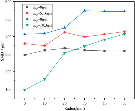
FIGURE 11. Radial distribution of SMD under conditions with different gas-liquid ratios.
Xu (Shun, 2016) found that the self-pulsation of the injector without recess was mainly caused by the attraction and polymerization of gas to the liquid film (Figure 12). When the momentum of gas reached a specific operating condition, the pressure inside the liquid film Pin decreased as the gas was entrained. In this case, the pressure of the outer gas was greater than that of the inside gas. The entrainment ability of the gas in the liquid film was greater than the inertial force of the liquid film. At this moment, the liquid film contracted and produced a bubble-like structure, resulting in an increase in pressure inside the bubble. When the internal pressure of the bubble was greater than its surface tension, the bubble broke, resulting in self-pulsation. Santanu (Sahoo and Gadgil, 2021)classified self-pulsation without recess into two types: large-amplitude pulsation (LAP) and small-amplitude pulsation (SAP).
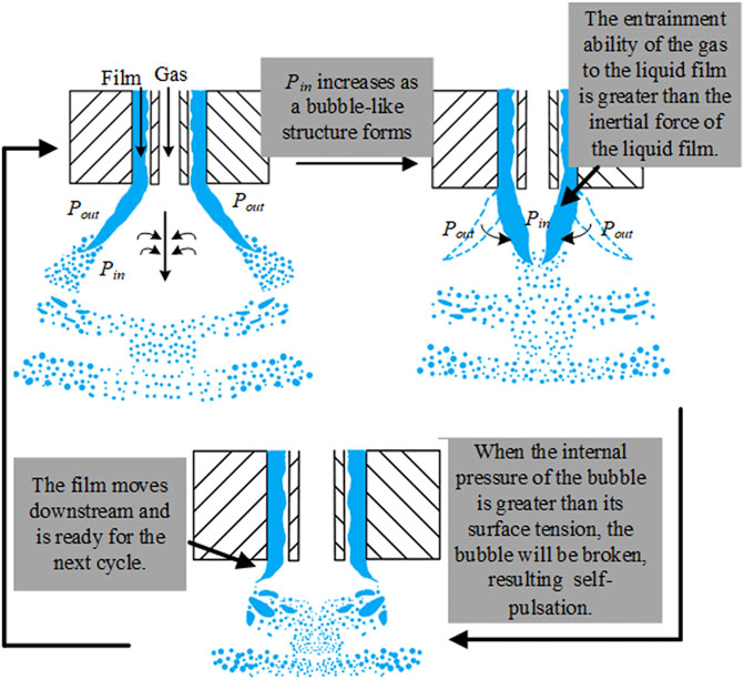
FIGURE 12. Spray self-pulsation mechanism without recess.
In this study, the adherent phenomenon was considered to be caused by self-pulsation. Figure 13A shows a cycle of the adherent phenomenon. As can be seen from Figure 13A, the liquid film contracted and then expanded in one cycle, and the liquid film touched the injector faceplate during expansion. Figure 13B shows the formation mechanism of the adherent phenomenon. Compared with no recess, when self-pulsation occurred under a small recess length, the position of the gas-liquid action moved upstream of the spray due to recess. Under the action of the airflow, the amplitude of the dominant surface wave increased. When the entrainment capacity of the gas was greater than the inertial force of the liquid, the liquid film contracted. When the internal pressure of the bubble was greater than its surface tension, the bubble broke at the trough of the dominant surface wave. Moreover, the pressure inside the bubble caused the crest of the liquid film near the injector orifices to impact the injector faceplate, forming adhesion. At Lr = 2 mm, when the gas mass flow rate or liquid mass flow rate was increased, the adhesion phenomenon weakened, which is due to the suppression of self-pulsation.
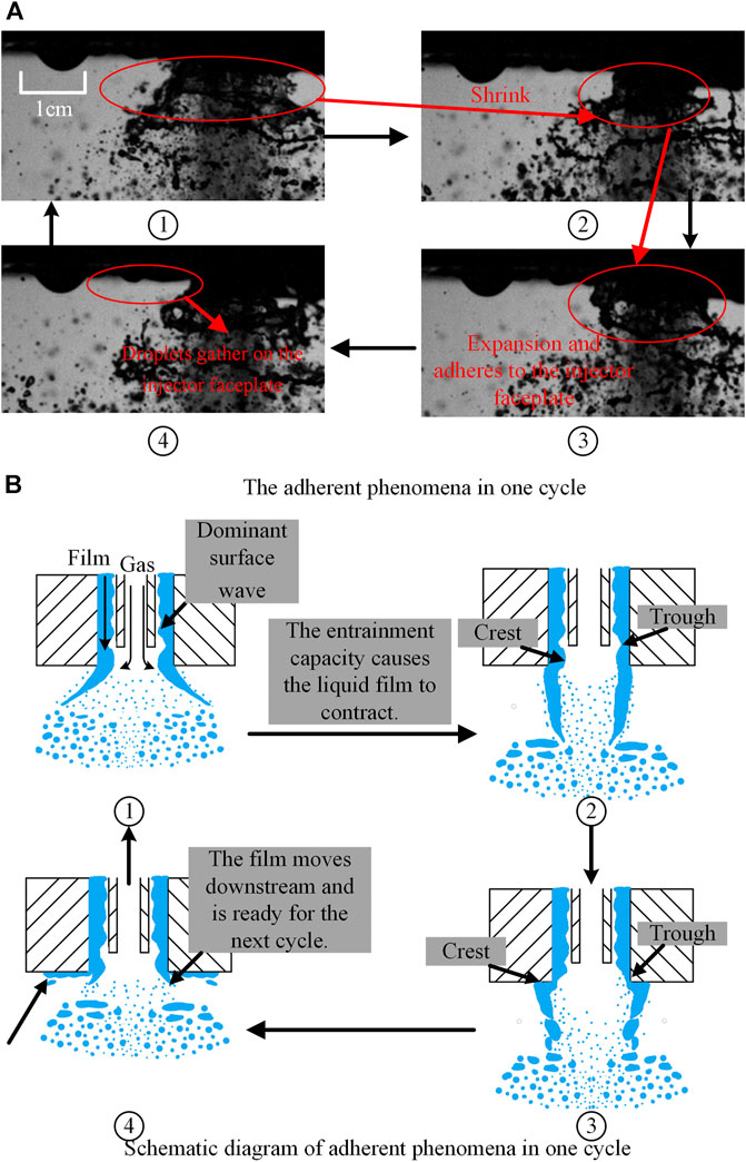
FIGURE 13. Mechanism of adherent phenomena with small recess. (A) The adherent phenomena in one cycle. (B) Schematic diagram of adherent phenomena in one cycle.
Lightfoot (Lightfoot et al., 2006) detected the gas-liquid shearing of the liquid film in the recess chamber, and shearing occurred in two forms. At a low momentum ratio, the surface waves appeared to grow uniformly. With an increase in the momentum ratio, the gas-liquid shearing effect became stronger. As a result, the thickness of the liquid film was unevenly distributed. The peaks of the surface waves increased and were stripped by the gas. This study considered that uneven surface waves under the injector in a long recess cause spray self-pulsation (Figure 14A). Moreover, this surface wave is formed by a strong gas-liquid shearing effect. Therefore, K-H instability is the root cause of spray self-pulsation under a long recess. As the liquid film flows in the recess chamber, the unstable shearing effect of K-H increases as the gas flow increases. This causes the surface wave of the liquid film to gradually change from a uniformly growing form to a form of gas stripping. When surface waves develop to a specific thickness (a more prominent peak is formed), they block the gas passageway. This causes the pressure of the gas passage to increase, pushing the liquid membrane rapidly downstream. When the gas and liquid move to the injector outlet, the liquid film loses wall constraints. Under the action of the central high-pressure gas, radial expansion occurs and breaks in the thinner part of the liquid film, and the thicker liquid film forms the “shoulder”. At the same time, the central high-pressure gas pressure is released and rapidly reduced. The thinner liquid film is squeezed to the center less than the external ambient gas pressure, forming a “neck.” Figure 14B is the image taken in the experiment, It can be seen from figure that the “shoulder” has been formed after the liquid film flows out injector orifice. This is consistent with the self-pulsation mechanism proposed in this study. In the experiment (Figure 7), it was found that the “shoulder” liquid flow of the spray was larger and the “neck” liquid flow was small. This is due to the thicker liquid film forming the “shoulder” and the thinner liquid film forming the “neck."
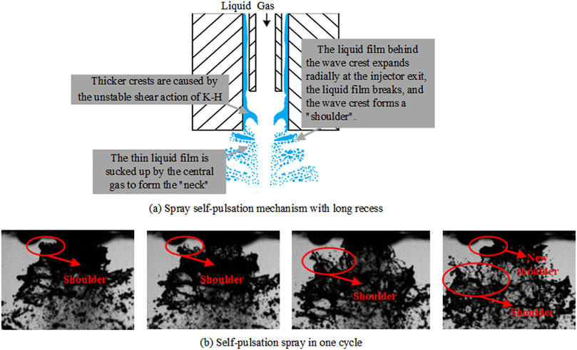
FIGURE 14. Self-pulsation mechanism with long recess.
Figure 15 shows the relationship between the operating condition range of the injector self-pulsation and the recess. It can be seen from the figure that when the recess length Lr = 0 mm, the spray produces self-pulsation. Under the same gas-liquid ratio, the recess length increases to 2 mm, and the spray adhesion phenomenon occurs. It is further confirmed that the adhesion phenomenon is caused by self-pulsation. When the recess length Lr = 7 mm, the self-pulsation operating condition range is very different from the range under the small recess length.
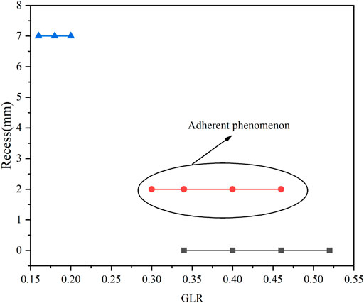
FIGURE 15. Self-pulsation operating condition range (ml = 20 g/s).
In the present study, the self-pulsation of a gas-centered swirl coaxial injector was investigated experimentally. The effects of recess and gas-liquid ratio on the spray pattern, spray angle, and droplet size of a GCSC injector were analyzed. The following conclusions can be drawn from this study:
1. Recess has a significant influence on the shape of self-pulsation. Without recess, when spray self-pulsation occurs, both the center and the outside of the spray oscillate. The tiny droplets at the spray center oscillate, with the periphery of the spray being characterized by periodic “shoulder.” The spray adheres to the panel plane under the same operating conditions but with a small recess (2 mm). With a long recess (7 mm), when spray self-pulsation occurs, the spray periodically forms “shoulder” and “neck."
2. The gas-liquid ratio is an important parameter of the injection conditions. With an increase in the gas-liquid ratio, the breaking modes of the liquid film are wave-assisted sheet breakup, perforated broken, segmented sheet breakup, self-pulsation breakup, and air-blasted breakup. In particular, with the increase in the gas mass flow rate, the tiny droplets at the center of the self-pulsation spray become dense gradually.
3. During self-pulsation, the spray particle size also oscillates. This will lead to a wider distribution of spray in the radial direction, which enhances the atomization effect of the central spray to a certain extent. The radial distribution of SMD is small at the center, but it increases sharply outward. With an increase in the spray particle size outside, the non-uniformity of the SMD distribution is rapidly increased, and the spray quality deteriorates sharply.
4. Recess determines the injector’s self-pulsation mechanism. The mechanism of self-pulsation of the injector without recess is the leading action of the central gas, and the mechanism of self-pulsation of the injector under large recess is the shearing action of the K-H instability on the liquid film.
The original contributions presented in the study are included in the article/Supplementary Material, further inquiries can be directed to the corresponding author.
CJ main contributions were experiments, data processing and writing, YX and YG were the main contributors to the experiment, WC and YT contributed primarily to data processing, XL and WN mainly provided financial support for the experiment.
The authors would like to express their sincere acknowledgments for support from the National Natural Science Foundation of China (Grant Nos. 12002386, 51876219).
The authors declare that the research was conducted in the absence of any commercial or financial relationships that could be construed as a potential conflict of interest.
All claims expressed in this article are solely those of the authors and do not necessarily represent those of their affiliated organizations, or those of the publisher, the editors and the reviewers. Any product that may be evaluated in this article, or claim that may be made by its manufacturer, is not guaranteed or endorsed by the publisher.
Bai, X., Cheng, P., Sheng, L., Li, Q., Zhang, X., and Kang, Z. (2019). Effects of Backpressure on Self-Pulsation Characteristics of Liquid-Centered Swirl Coaxial Injectors. Int. J. Multiphase Flow 116, 239–249. doi:10.1016/j.ijmultiphaseflow.2019.04.017
Bai, X., Li, Q., Cheng, P., Sheng, L., and Kang, Z. (2018). Investigation of Self-Pulsation Characteristics for a Liquid-Centered Swirl Coaxial Injector with Recess. Acta Astronautica 151, 511–521. doi:10.1016/j.actaastro.2018.07.002
Bai, X., Sheng, L., Li, Q., Cheng, P., and Kang, Z. (2020). Effects of Annulus Width and post Thickness on Self-Pulsation Characteristics for Liquid-Centered Swirl Coaxial Injectors. Int. J. Multiphase Flow 122, 103140. doi:10.1016/j.ijmultiphaseflow.2019.103140
Bazarov, V. (1996). Influence of Propellant Injector Stationary and Dynamic Parameters on High Frequency Combustion Stability, 32nd Joint Propulsion Conference and Exhibit, Cleveland, OH.
Bazarov, V. (1998). Non-linear Interactions in Liquid-Propellant Rocket Engine Injectors. AIAA/ASME/SAE/ASEE Joint Propulsion Conference and Exhibit. doi:10.2514/6.1998-4039
Bazarov, V. (1995). Self-pulsations in Coaxial Injectors with central Swirl Liquid Stage, 31st Joint Propulsion Conference and Exhibit, San Diego, CA, USA. doi:10.2514/6.2014-3411
Gujeong, P., Lee, I., Lee, J., and Yoon, Y. (2014). Measurement of Film Thickness in Gas-Centered Swirl Coaxial Injectors. 50th AIAA/ASME/SAE/ASEE Joint Propulsion Conference, Cleveland, OH. doi:10.2514/6.2014-3411
Harrje, D. T. (1972). Liquid Propellant Rocket Combustion Instability, Scientific and Technical Information Office. Washington, DC: National Aeronautics and Space.
Im, J.-H., Kim, D., Han, P., Yoon, Y., and Bazarov, V. (2009). Self-Pulsation Characteristics of A Gas-Liquid Swirl Coaxial Injector. Atomiz Spr 19, 57–74. doi:10.1615/atomizspr.v19.i1.40
Im, J. H., Cho, S., Yoon, Y., and Moon, I. (2015). Comparative Study of Spray Characteristics of Gas-Centered and Liquid-Centered Swirl Coaxial Injectors. J. Propulsion Power 26, 1196–1204. doi:10.2514/1.48436
Im, J. H., Kim, D. J., Yoon, Y. B., and Bazarov, V. (2005). Self-Pulsation Characteristics of A Swirl Coaxial Injector With Various Injection And Geometric Conditions. Aiaa/asme/sae/asee Joint Propulsion Conference & Exhibit, Tucson, Arizona. doi:10.2514/6.2005-3749
Im, J. H., and Yoon, Y. (2008). The Effects of the Ambient Pressure on Self-Pulsation Characteristics of a Gas/Liquid Swirl Coaxial Injector. AIAA/ASME/SAE/ASEE Joint Propulsion Conference & Exhibit, Hartford, CT. doi:10.2514/6.2008-4850
Ismailov, M., and Heister, S. (2009). Nonlinear Modeling of Classical Swirl Injector Dynamics. Aiaa/asme/sae/asee Joint Propulsion Conference & Exhibit, Denver, Colorado.
Jeon, J., Hong, M., Han, Y. M., and Lee, S. Y. (2011). Experimental Study on Spray Characteristics of Gas-Centered Swirl Coaxial Injectors. J. Fluids Eng. 133, 121303. doi:10.1115/1.4005344
Jin, Z., Xiaoping, H., Yuhui, H., and Zhenguo, W. (1997). A Study of the Mixing Characteristics of Gas-Liquid Coaxial Swirling Injector of Liquid Rocket Engine. J National University Defense Tech. 19, 9–13.
Jin, Z., Xiaoping, H., Yuhui, H., Zhenguo, W., Liangsheng, Z., and Xiaoqing, Y. (1996). AN EXPERIMENTAL STUDY ON ACOUSTIC Characteristics of Gas-liquid Coaxial Injector Of Liquid Rocket Engine. J Propulsion Technology 17, 37–41.
Joseph, A., Sakthikumar, R., and Sivakumar, D. J. J. o. F. E. (2020). Experimental Characterization of Sprays in a Recessed Gas-Centered Swirl Coaxial Atomizer. J. Fluids Eng. 142, 4. doi:10.1115/1.4045986
Kang, Z., Li, Q., Cheng, P., Zhang, X., and Wang, Z. (2016). Effects of Recess on the Self-Pulsation Characteristics of Liquid-Centered Swirl Coaxial Injectors. J. Propulsion Power 32, 1–9. doi:10.2514/1.b35632
Kim, J. G., Han, Y. M., Choi, H. S., and Yoon, Y. (2013). Study on spray Patterns of Gas-Centered Swirl Coaxial (GCSC) Injectors in High Pressure Conditions. Aerospace Sci. Technol. 27, 171–178. doi:10.1016/j.ast.2012.08.004
Lightfoot, M., Danczyk, S. A., and Talley, D. G. (2006). Atomization in GasCentered Swirl-Coaxial Injectors. ILASS Americas, 19th Annual Conference on Liquid Atomization and Spray Systems, Toronto, Canada, May 2006.
Matas, J. P., Hong, M., and Cartellier, A. (2014). Stability of a Swirled Liquid Film Entrained by a Fast Gas Stream. Phys. Fluids 26, 121303–121366. doi:10.1063/1.4871395
Ramadan, O. B., Matida, E. A., Hughes, P. M., and Hughes], R. J. F. (2012). Atomization Performance of Petroleum Coke and Coal Water Slurries from a Twin Fluid Atomizer. Fuel 98, 183–193. doi:10.1016/j.fuel.2012.02.042
Sahoo, S. K., and Gadgil, H. (2021). Dynamics of Self-Pulsation in Gas-Centered Swirl Coaxial Injector. An Exp. Study J Propulsion Power 37. doi:10.2514/1.b38043
Shun, X. (2016). Research on the Dynamic spray Characteristics of the Gas-Centered Swirl Coaxial Injector. National University of Defense Technology, Changsha.
Sivakumar, D., and Kulkarni, V. (2011). Regimes of spray Formation in Gas-Centered Swirl Coaxial Atomizers. Exp. Fluids 51, 587–596. doi:10.1007/s00348-011-1073-7
Xuan, L., Tian, L., Jinli, H., Shaohua, Z., and Xu, X. (2013). The Preliminary Study of Oxygen-Centered Kerosene-Swirl Coaxial Injector. Aiaa/asme/sae/asee Joint Propulsion Conference, Cleveland, OH.
Yang, L.-j., Ge, M.-h., Zhang, M.-z., Fu, Q.-f., and Cai, G.-b. (2008). Spray Characteristics of Recessed Gas-Liquid Coaxial Swirl Injector. J Propulsion Power 24, 1332–1339. doi:10.2514/1.23977
Yoon, J., Chung, J. M., and Yoon, Y. (2013). Study on Self-Pulsation Characteristics of Gas/Liquid Shear Coaxial Injector with Annular Liquid Sheets. Aiaa/asme/sae/asee Joint Propulsion Conference & Exhibit, Atlanta, Georgia.
Yuhui, H. (2001). Theoretical, numerical Simulation and Experimental Investigations of Combustion Instability in Liquid Rocket Engine. National University of Defense Technology, Changsha.
Zhenguo, W. (2012). Modeling and Numerical Simulations of Internal Combustion Process of Liquid Rocket Engines. National Defense Industry Press, Beijing.
Zhongtao, K., Li, Q., Peng, C., Xinqiao, Z., and Zhen-guo, W. (2016). Effects of Self-Pulsation on the spray Characteristics of gasCliquid Swirl Coaxial Injector. Acta Astronautica 127, 249–259. doi:10.1016/j.actaastro.2016.05.038
Zhongtao, K. (2016). The Unsteady Atomization Mechanism and Combustion Characteristics of Gas-Liquid Swirl Coaxial Injector. National University of Defense Technology, Changsha.
n Number of tangential holes of external injector
Do diameter of liquid orifice (mm)
Dg diameter of gas orifice (unit:mm)
hgap gap thickness (unit: mm)
dt diameter oftangential inlet (unit: mm)
Lr recess length (unit:mm)
Di droplet diameter(unit:mm)
Ni the number of droplets with a diameter of Di.
m mass flow rate
Subscripts
g gas
l liquid
Keywords: gas-centered coaxial swirl injector, self-pulsation, SMD, spray angle, atomization
Citation: Jiang C, Xie Y, Gao Y, Chu W, Tong Y, Li X and Nie W (2021) Influence of Self-Pulsation on Atomization Characteristics of Gas-Centered Swirl Coaxial Injector. Front. Energy Res. 9:760150. doi: 10.3389/fenrg.2021.760150
Received: 17 August 2021; Accepted: 13 September 2021;
Published: 28 September 2021.
Edited by:
Xiao Liu, Harbin Engineering University, ChinaReviewed by:
Jian Liu, Central South University, ChinaCopyright © 2021 Jiang, Xie, Gao, Chu, Tong, Li and Nie. This is an open-access article distributed under the terms of the Creative Commons Attribution License (CC BY). The use, distribution or reproduction in other forums is permitted, provided the original author(s) and the copyright owner(s) are credited and that the original publication in this journal is cited, in accordance with accepted academic practice. No use, distribution or reproduction is permitted which does not comply with these terms.
*Correspondence: Yiheng Tong, eWloZW5nX3RvbmdAc2luYS5jb20=
Disclaimer: All claims expressed in this article are solely those of the authors and do not necessarily represent those of their affiliated organizations, or those of the publisher, the editors and the reviewers. Any product that may be evaluated in this article or claim that may be made by its manufacturer is not guaranteed or endorsed by the publisher.
Research integrity at Frontiers
Learn more about the work of our research integrity team to safeguard the quality of each article we publish.