 Hongbo Liu
 Li Sun
95% of researchers rate our articles as excellent or good
Learn more about the work of our research integrity team to safeguard the quality of each article we publish.
Find out more
ORIGINAL RESEARCH article
Front. Energy Res. , 27 October 2021
Sec. Smart Grids
Volume 9 - 2021 | https://doi.org/10.3389/fenrg.2021.755524
This article is part of the Research Topic Women in Science: Energy Research View all 8 articles
In order to deeply explore the transient stability mechanism of the AC/DC hybrid system, this paper analyzes the rotor angle stability of the two-area AC/DC hybrid system. The system is analyzed after subjecting it to large disturbances in the AC system and for different operating conditions, qualitatively and quantitatively. The influence of factors, such as the AC operating point of the system and the proportion of DC transmission power, have been considered for improving the rotor motion equation. Subsequently, the transient characteristics of the hybrid system are analyzed after being subjected to disturbances. The power angle stability margin index is obtained, based on which the transient characteristics after DC blocking are analyzed, and the coordinated control strategy with the least control cost is proposed. The results are verified using the two-area AC/DC parallel transmission system network model. The study provides the reference for ensuring the security and stability of the hybrid AC/DC power grid.
High Voltage Direct Current (HVDC) has become the first choice for long-distance power transmission due to its advantages of low line loss, large transmission capacity, and adjustable power (Huang et al., 2009). China has formed a multi-area interconnected AC/DC transmission system. With the continuous development of AC/DC hybrid power grid, the grid pattern, its operational characteristics and the power supply structure are undergoing major changes (Barnes et al., 2017; Wang et al., 2021). However, the cross-regional coupling characteristics of the AC and the DC systems, enhance the mutual influence and thus, results in complex transient stability characteristics of the hybrid system (Mao et al., 2021).
Commutation failure (CF) is the abnormal behavior of a semi-controlled DC converter valve composed of thyristors. CFs at the DC inverter side threaten the stable operation of the power system (Wang et al., 2019; Hong et al., 2021). If the fault is not cleared in time, it may cause a power outage of the AC system on the inverter side (Xue et al., 2018). The instability of the system rotor angle caused by the CF is one of the main stability problems faced by the AC/DC hybrid system (Geeganage et al., 2015; Gonzalez-Torres et al., 2021). Most of the current researches on rotor angle stability aims at the transient rotor angle stability of the system. The characteristics of the DC power dip caused by the sending-side fault has been studied by (Tu et al., 2016), who also analyzed the rotor angle instability mode of the sending-side system caused by the DC fault dip from the mechanism. The problem of insufficient moment of inertia of the system after the accident has been studied by (Tina et al., 2018), who also proposed a method for evaluating the moment of inertia of the system using an independent system, to ensure the transient stability of the system. Siddiqui et al. (2016) used the data provided by the phasor measurement units to predict the system’s risk of instability, after a large disturbance. They also proposed an online emergency control strategy for possible situations. A new method for identifying the rotor angle stability of the power system has been proposed by establishing a multi-condition discrete Markov power system model with cascading failures and by using linear matrix inequality (LMI) tools (Ma et al., 2016). Some researchers have used advanced machine learning technology to warn and prevent the potential emergency of power system (Hiraiwa et al., 2015; Yang Shaobo et al., 2020; Zhou et al., 2021). To quickly quell the impact of large disturbances during faults and keep the system safe and stable, it is difficult for a single type of control measure to meet the control requirements (Haleem et al., 2019; Watson and Lestas, 2021). So it is necessary to formulate corresponding coordinated control strategies (Renedo et al., 2016; Gan et al., 2018; Wang et al., 2019).
The main contributions of the paper can be summarized as follows: Taking a two-area AC/DC parallel transmission system as the example, to study the influence of AC operating point on the transient rotor angle stability of AC/DC hybrid system. This paper reflects the change of AC operating point of the system through two different operating conditions of the hybrid system. Based on the equivalent rotor motion equation, the key factors affecting the stability of the hybrid system are quantitatively analyzed through the corresponding power characteristic curves of the hybrid system under two working conditions. It was proved that in a certain range, the increase of DC power transmission ratio has the opposite effect on the transient rotor angle stability of hybrid system under different working conditions. Then, based on the power characteristic curve of the system have adopted DC blocking and load cutting, the coordinated control strategy is determined quantitatively. These research results provide a basis for the distribution of DC transmission power and the adoption of system control strategy under different operation modes of AC/DC hybrid system.
The article is arranged as follows: The Power Characteristic Curve of System section determines the power characteristic curves of the system under different operating conditions. The Stability Margin Index and Transient Stability Analysis of System section analyzed main influencing factor of the transient rotor angle stability by the stability margin index. The Control strategy of Hybrid System section determines the coordinated control strategy with a minimum control cost. Simulation analysis section demonstrates the effectiveness of the theoretical results by the simulation of the two-area IEEE-39 network model using an advanced digital power system simulator (ADPSS).
The schematic diagram of the equivalent model of the two-area AC system is shown in Figure 1.
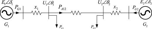
FIGURE 1. AC system equivalent model.
In the simplified model,
For the convenience of analysis, the following assumptions are made for the system:
1) Ignoring the mechanical power change of equivalent generators G1 and G2, it is assumed that the values of PG1 and PG2 are constant
2) The equivalent load of transmission network and receiving terminal is represented by constant power load model.
3) It is assumed that there is weak interconnection between area 1 and area 2, that is, when the reactance x12 of the tie line is much greater than the internal impedance of the power grid at the sending and receiving end x1,x2, it can be approximated that
Under this assumption, and the rotor motion of the equivalent generator in area 1 and area 2 of the hybrid power system is:
Where,
The Eq. 1, 2 is further simplified, and the results are as follows:
In the formula, the equivalent rotor angle is
According to Eq. 3, the power characteristic curve of AC system is shown in Figure 4A.
The two-area network model for AC/DC parallel transmission model was shown in Figure 2, and its schematic diagram of the equivalent model is shown in Figure 3.
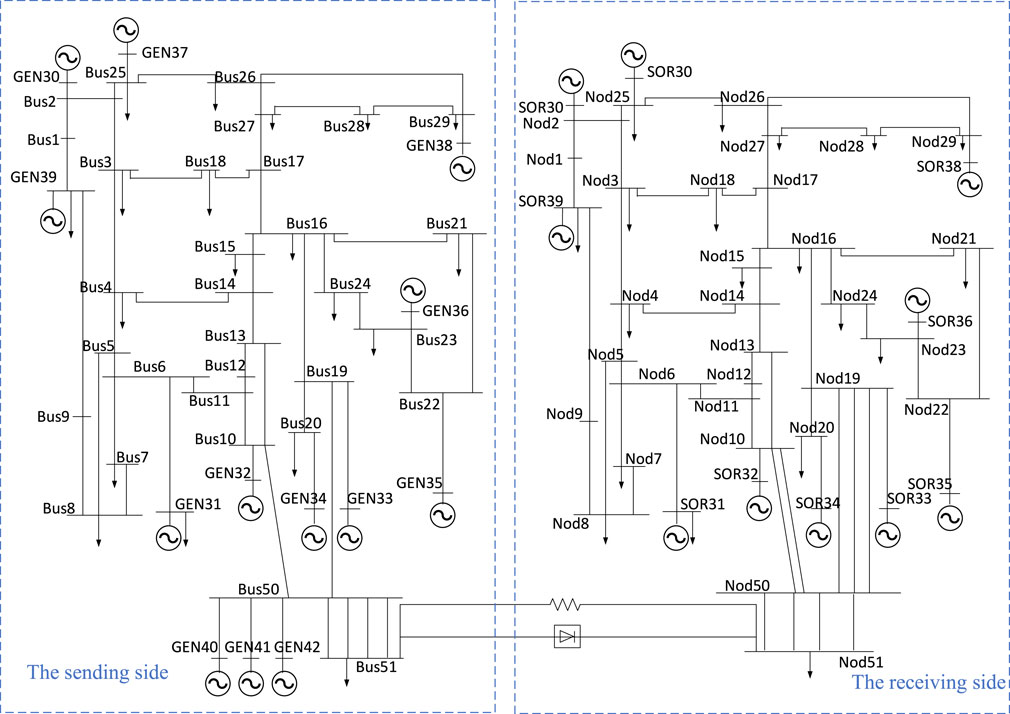
FIGURE 2. The two-area network model for AC/DC parallel transmission.
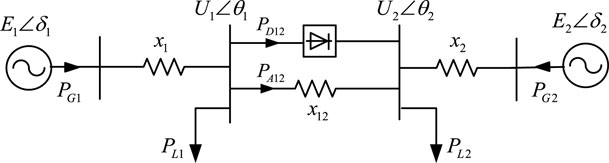
FIGURE 3. The equivalent model of system in Figure 2.
In the simplified model, the sending and the receiving power grids are interconnected synchronously through the AC/DC transmission channels.
Under this same assumption in previous section, the rotor motion equation of the equivalent generator in area 1 and area 2 of the hybrid power system is:
the two-machine system shown in Eq. 4 is further simplified, and the results are as follows:
In the formula, the equivalent rotor angle is; the equivalent mechanical power of the two-area AC/DC hybrid system is
According to Eqs 3, 5, when the DC line is connected to the system, the equivalent mechanical power of the system remains unchanged,
Point a is the stable operation point of the traditional AC system, in order to meet the operation conditions of the constant AC operation point, the stable operation point of the hybrid system shall be moved from point a to point A. After the DC line is connected to the traditional AC grid, the power characteristic curve in this operation state is shown in Figure 4B.
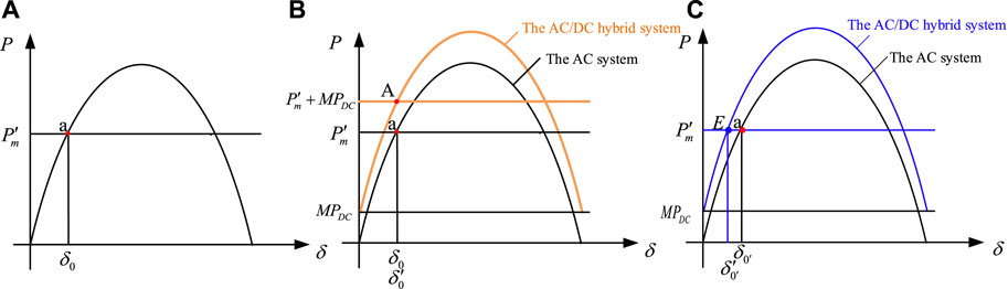
FIGURE 4. The power characteristic curve of systems. (A) Power characteristic curve of AC system (B) Power characteristic curve of AC/DC system under operation condition 1 (C) Power characteristic curve of AC/DC system under operation condition 2
After the DC system is connected to the traditional AC system, equivalent mechanical power remains unchanged and the operating point of the system has changed. The equivalent power characteristic curve of the total transmission power remains unchanged operating condition is shown in Figure 4C.
From the perspective of energy, the problem of the power system transient stability is whether the impact energy of the system can be essentially absorbed by itself (Bhui and Senroy, 2017). For the traditional two area AC system, when the three-phase grounding short-circuit fault occurs in the receiving AC system, the impact energy accumulated in the transient process of the system after the fault can be approximately expressed by the acceleration area
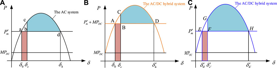
FIGURE 5. Schematic diagram of system acceleration and deceleration area (A) Power characteristic curve of AC system (B) Power characteristic curve of AC/DC system under operation condition 1 (C) Power characteristic curve of AC/DC system under operation condition 2.
It can be concluded that the criterion of power system transient power angle stability is the difference
Similarly, when the acceleration and deceleration areas of AC/DC hybrid system under different working conditions are determined, the transient rotor angle stability criterion of hybrid system under different working conditions can be obtained.
The power characteristic curve of constant AC operating point operation state is shown in Figure 5B. At
The power characteristic curve of constant total transmission power operation state is shown in Figure 5C. The system stability margin index
According to Eqs 6, 7, the main factors affecting the stability of AC/DC hybrid system are DC power transmission ratio
For Eqs 6, 7, the sensitivity of DC transmission power ratio
From the Eq. (8), when the AC operating point does not change, the system stability margin index
From the Eq. (9), when the total transmitted power remains unchanged, the system stability margin index
In the basic control strategy of the AC/DC hybrid system, the PI regulator on the rectifier side corresponds to the constant current control mode, and when its output reaches the lower limit (5°), it switches to the minimum firing angle control mode. Two different PI regulators on the inverter side correspond to two control modes of constant current and constant extinction angle respectively, and take the minimum output of the two regulators as the firing angle command on the inverter side (Faruque et al., 2005). The basic control strategy diagram of the inverter side is shown in Figure 6.
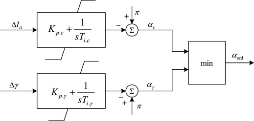
FIGURE 6.
In order to improve the commutation failure immunity performance of the inverter side, the commutation failure prevention control (CFPREV) is added into the control strategy of the hybrid system, and is shown in Figure 7.
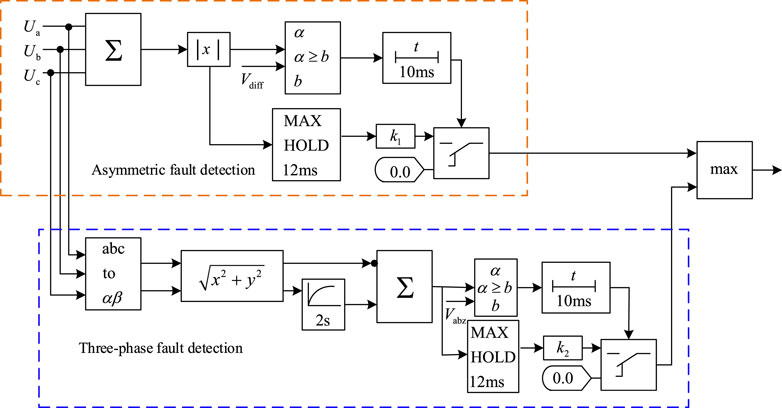
FIGURE 7. The CFPREV system control logic.
The upper part is the asymmetric fault detection, when the zero-sequence component of AC voltage exceeds the threshold
In order to avoid more serious damage to the system, the blocking strategy is usually adopted after three commutation failures in the DC system.
In Eqs 6, 7, set
The power characteristic curves of AC/DC hybrid system after two working conditions when the DC blocking strategy is adopted, are shown in Figure 8.
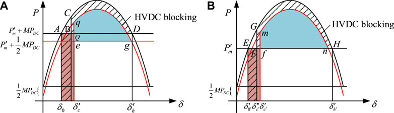
FIGURE 8. Power characteristic curve of single HVDC blocking (A) the AC operating point remains unchanged (B) the total transmission power remains unchanged.
During the HVDC single-pole blocking, the transmission power of the DC line is reduced to half of the original transmission power. When the AC operating point of the system remains unchanged, equivalent electromagnetic power and the curve of the equivalent mechanical power move down. When the total transmission power of the system does not change, only the equivalent electromagnetic power curve moves down.
To maintain the stability of the system, when the HVDC single-pole blocking strategy is only used the acceleration energy increases, the deceleration energy accumulated during two working conditions of the transient process decreases, the stability margin index
After the HVDC blocking, the sending side system has a large surplus of active power, and the difference in rotor angle between two-area equivalent units is further widened, it is necessary to combine the conventional stability control measures of the power grid to maintain the stability of the system rotor angle. Machine-cutting and load-cutting measures can reduce the transient accumulated energy during the process of system failure. In two area equivalent units, the increase in the difference between the generator’s speed and the rotor angle difference, is restrained, which is helpful to keep the rotor angle stable.
From the above analysis, when the system is unstable, only using DC blocking as an emergency control measure will worsen the rotor angle stability of the system. To maintain transient stability of AC/DC hybrid system, it is necessary to adopt coordinated control measures for DC blocking and for the generator and load cutting. The flow chart for coordinated control strategy of AC/DC hybrid system is shown in Figure 9.
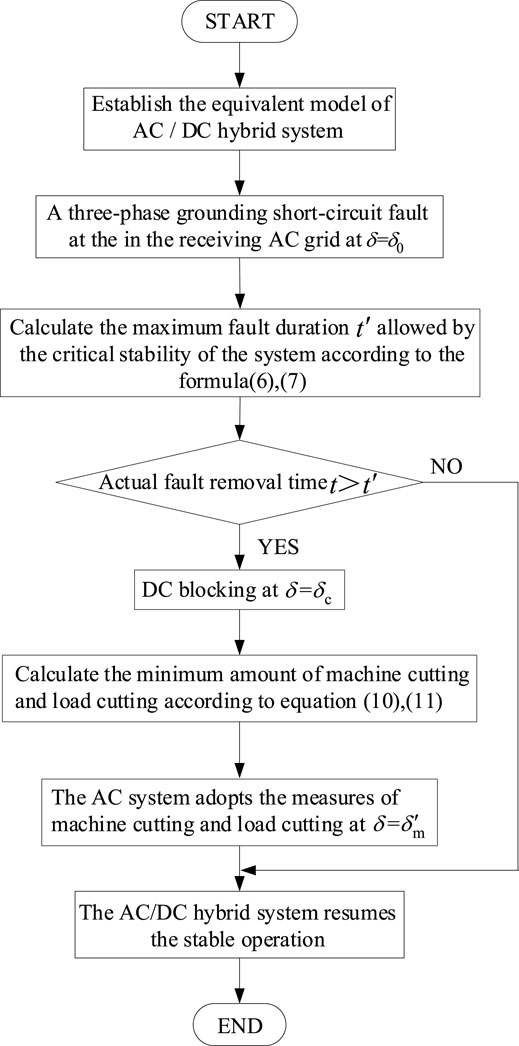
FIGURE 9. The flow chart for coordinated control strategy.
After the coordinated control strategy is adopted for the AC/DC hybrid system, the equivalent power characteristic curve for two operating condition is shown in Figure 10.
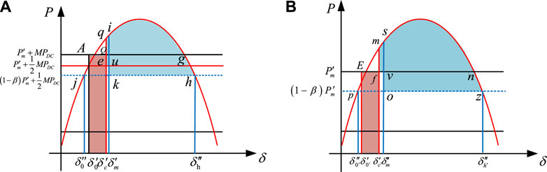
FIGURE 10. Power characteristic curve of coordinated control (A) the AC operating point remains unchanged (B) the total transmission power remains unchanged.
When using coordinated control, to minimize the impact on the stable operation of the AC/DC hybrid system, to maximize the reliability of the power supply, re-draw the stability margin index
According to Figure 10, after the coordinated control strategy is adopted, the stability margin index of two operation condition is
Let
To verify the influence of DC connection on the rotor angle stability under two different conditions, the relationship between the proportion of DC transmission power and the transient stability of the system, and the effectiveness of the cooperative control strategy, the two-area network model for AC/DC parallel transmission model was built in advanced digital power system simulator (ADPSS), which was developed by China electric power research institute. The extended IEEE39 bus system and the standard IEEE39 nod system are interconnected by AC and DC lines respectively as the sending and receiving sides (Sun et al., 2020), which were shown in Figure 2. The total output of 13 generator sets at the sending end is 5,612.8 MW, the total output of 10 generator sets at the receiving end is 5,632.8 MW, and the total load at the sending and receiving end is 10,595.7 MW. The sending and receiving end units are interconnected with AC transmission lines through a rated 500 kV DC transmission line.
Under different DC transmission ratios, the AC line transmission power is kept unchanged by changing the generator output and the load size to maintain the AC operating point of the AC/DC hybrid system. Setting a three-phase grounding short-circuit fault at the NOD_50 bus in the receiving side of the AC grid at 5s, the fault is removed after 0.15s, the relative rotor angle curves of the GEN_33-SOR_39 and GEN_35-SOR_39 units are shown in Figures 11, 12.
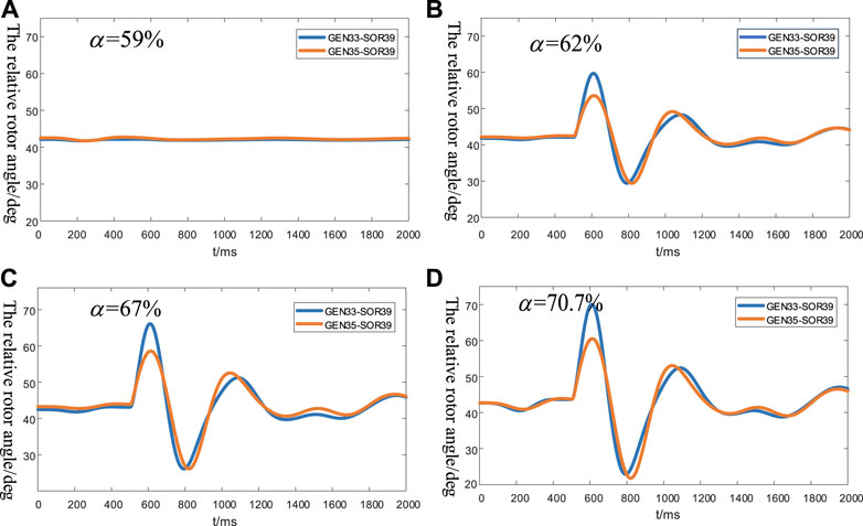
FIGURE 11. The relative angle curve of constant AC operating point (A) Relative angle curve of GEN33-SOR-39 and GEN35-SOR39 at α = 59% (B) Relative angle curve of GEN33-SOR-39 and GEN35-SOR39 at α = 62% (C) Relative angle curve of GEN33-SOR-39 and GEN35-SOR39 at α = 67% (D) Relative angle curve of GEN33-SOR-39 and GEN35-SOR39 at α = 70.7%.
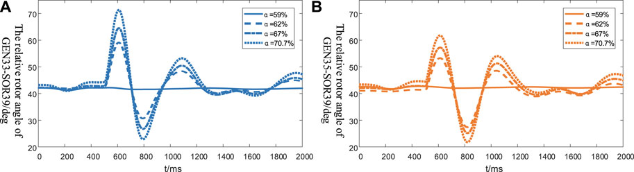
FIGURE 12. The relative angle curve under different DC power transmission ratio (A) The relative angle curve of GEN_33-SOR_39 (B) The relative angle curve of GEN_35-SOR_39.
When α = 59%, after removing the fault in 5.15 s, the relative rotor angle curve of the two sets of units has a small swing, when the system runs under this DC transmission ratio, it can absorb the impact energy of the fault in the hybrid system to a large extent, which can basically maintain the stable operation. With the gradual increase in the DC transmission ratio, the relative rotor angle swing amplitude gradually increases. When the DC ratio is the highest α = 70.7%, the swing amplitude of the relative rotor angle curve is the largest, the rotor angle instability of the AC/DC hybrid system is most obvious. In contrast, when α = 59%, the swing amplitude of the curve is the smallest, the hybrid system can basically maintain stability for the same failure.
Ensuring that the total transmission power of the system remains unchanged, with the above fault, the relative rotor angle curve of the above two groups is shown in Figures 13, 14.
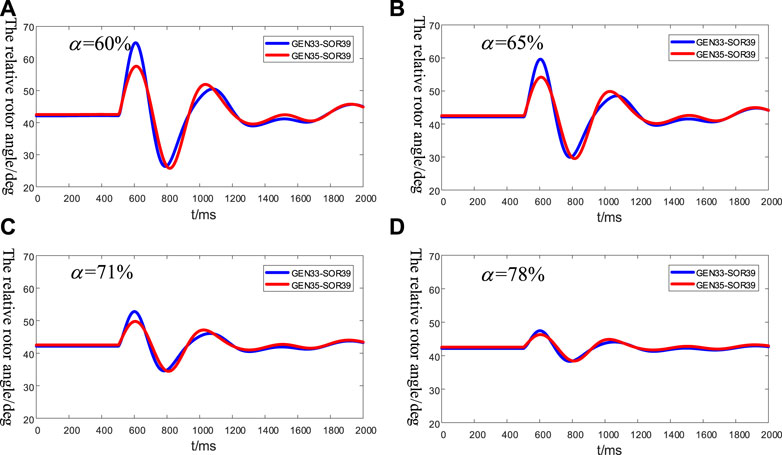
FIGURE 13. The relative angle curve of constant total transmission power (A) Relative angle curve of GEN33-SOR-39 and GEN35-SOR39 at α = 60% (B) Relative angle curve of GEN33-SOR-39 and GEN35-SOR39 at α = 65% (C) Relative angle curve of GEN33-SOR-39 and GEN35-SOR39 at α = 71% (D) Relative angle curve of GEN33-SOR-39 and GEN35-SOR39 at α = 78%.
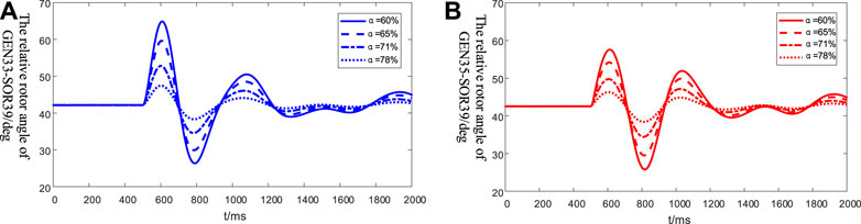
FIGURE 14. Relative angle curve under different DC power transmission ratio (A) The relative angle curve of GEN_33-SOR_39 (B)The relative angle curve of GEN_35-SOR_39.
When α = 60%, after the fault is removed, the corresponding relative rotor angle curve has the largest swing amplitude. When the system is running under this DC power transmission ratio, the ability to absorb the impact energy is weak, and after the failure, the instability is most obvious. With the gradual increase in the proportion of transmitted DC power, the relative rotor angle curve fluctuation amplitude gradually decreases. When α = 78%, the AC/DC hybrid system can basically maintain the stable operation of the rotor angle.
Under different DC ratios, the theoretical and simulation values of the maximum fault duration and limit cutting angle of the system corresponding to the two operating conditions are shown in Table 1.
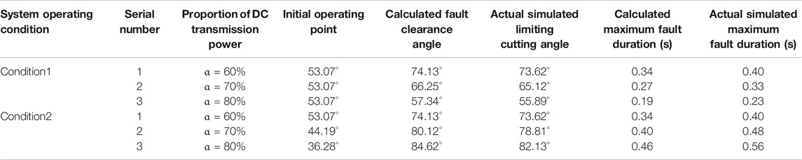
TABLE 1. Calculation and simulation results of limit cutting angle and maximum fault duration of hybrid system under different operating states.
From the simulation results and the theoretical analysis, the following conclusions can be drawn
When the system is in the operating condition the AC operating point remains unchanged, the higher the proportion of DC transmission power, the lower the stability margin of the system, and weaker the rotor angle stability of the system.
When the total transmission power of the system is unchanged and for the same fault, higher the proportion of DC power transmission, higher the stability margin of the system, and the stronger the rotor angle stability of the system.
Simulation Analysis of AC/DC Hybrid System Adopting Emergency Control Strategy.
To be close to the actual operating conditions, the transmission power of the DC line was changed to transmit 932 MW power, 267 MW power was transmitted by AC line, and so α = 71.75%. After the system operates stably for 5 s, a three-phase grounding fault is set at the NOD_50 bus at the receiving side in AC power grid, the fault is removed after 0.5s, the fault duration exceeds the maximum value that the system can sustain to maintain a stable operation. Figure 15 shows the relative rotor angle curves of the unit GEN_35-SOR_39 after the failure occurs.
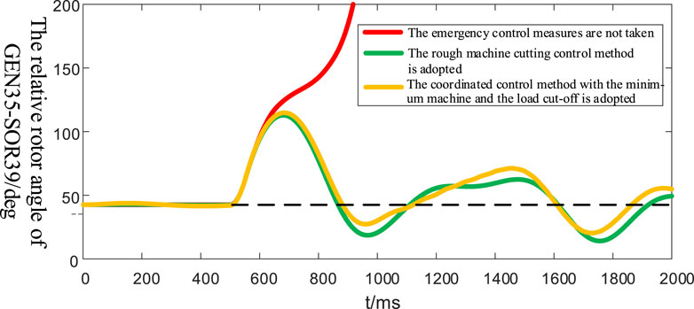
FIGURE 15. Relative angle curve of GEN_35-SOR_39 under different control measures.
From Figure 15, it can be observed that if emergency control measures are not taken, the AC/DC hybrid system cannot absorb the impact energy by itself, the rotor angle of the system loses stability. Using the other two emergency control measures can make the relative rotor angle of the unit return to a stable value, and they significantly improve the stability of the system’s rotor angle. When the coordinated control method with the minimum machine and the load cut-off is adopted, the difference between the relative rotor angle of the unit after the AC/DC hybrid system is restored to stability and the relative rotor angle during stable operation is small, which further improves the rotor angle stability of the system.
In Figure 16, when the emergency control measures are not taken, the bus voltage is obviously unstable and it fluctuates sharply. Although the bus voltage has increased, the degree of fluctuation has been reduced after adopting rough machine and load cutting control measures, but it is still unable to restore stability. After adopting the coordinated control measure with the minimum machine and load cut-off, the bus voltage can almost return to the steady-state value, and the trend of the voltage recovery process is relatively gentle and the voltage reaches stability.
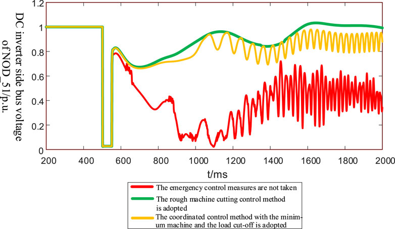
FIGURE 16. Voltage of NOD_51 under different control measures.
When the AC operation point of the hybrid system is changed, the comparison of theoretical calculation and simulation verification results of parameters such as minimum generator tripping and load shedding are shown in Table 2.
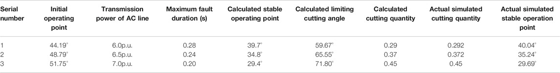
TABLE 2. Calculation and simulation results of generator tripping and load shedding of sending and receiving AC power systems with different operation points.
The simulation results show that the emergency control strategy is conducive to restoring the rotor angle stability of the system. Moreover, the coordinated control method with the minimum amount of machine and load cutting is an effective means to further ensure the safe and stable operation of the system.
This paper addresses the transient stability of the two-area system, considering two operating conditions. Based on the perspective of energy, the transient rotor angle stability margin index of the hybrid system is determined, and the key influencing factors are quantitatively analyzed. It can be concluded that when the AC operating point of the system does not change after DC is connected, the system rotor angle stability decreases with the increase in the DC power transmission ratio. When the total transmission power does not change, the opposite was observed. The influence of the control strategies on the rotor angle stability of the system was analyzed. After DC blocking, the stability of the system under the two working conditions further declines. To restore the stability of the system, the stability margin index was redefined, and the coordinated control strategy with a minimum control cost was determined. A two-area network model for the AC/DC parallel transmission was built with the ADPSS software, and the effectiveness of the theoretical results were demonstrated.
The raw data supporting the conclusions of this article will be made available by the authors, without undue reservation.
LS proposed the methodology. HL and SZ designed the model and the computational framework and analyzed the data. SZ wrote the original draft which was reviewed and edited by CZ and XP. All authors agree to be accountable for the content of the work.
This research was financially supported by National Key Research and Development Program of China (2017YFB0902000).
The authors declare that the research was conducted in the absence of any commercial or financial relationships that could be construed as a potential conflict of interest.
All claims expressed in this article are solely those of the authors and do not necessarily represent those of their affiliated organizations, or those of the publisher, the editors and the reviewers. Any product that may be evaluated in this article, or claim that may be made by its manufacturer, is not guaranteed or endorsed by the publisher.
Barnes, M., Van hertem, D., Teeuwsen, S. P., and Callavik, M. (2017). HVDC Systems in Smart Grids. Proc. IEEE 105, 2082–2098. doi:10.1109/jproc.2017.2672879
Bhui, P., and Senroy, N. (2016). Real Time Prediction and Control of Transient Stability Using Transient Energy Function. IEEE Trans. Power Syst. 32 (2), 1. doi:10.1109/tpwrs.2016.2564444
Daochun Huang, D., Yinbiao Shu, Y., Jiangjun Ruan, J., and Yi Hu, Y. (2009). Ultra High Voltage Transmission in China: Developments, Current Status and Future Prospects. Proc. IEEE 97 (3), 555–583. doi:10.1109/jproc.2009.2013613
Faruque, M. O., Zhang, Y., and Dinavahi, V. (2005). Detailed modeling of CIGRE HVDC benchmark system using PSCAD/EMTDC and PSB/SIMULINK. IEEE Trans. Power Deliv. [J] 21, 378–387.
Gan, G., Zhu, Z., Geng, G., and Jiang, Q. (2018). An Efficient Parallel Sequential Approach for Transient Stability Emergency Control of Large Scale Power System. IEEE Trans. Power Syst. (6), 1. doi:10.1109/tpwrs.2018.2826534
Geeganage, J., Annakkage, U. D., Weekes, T., and Archer, B. A. (2015). Application of Energy-Based Power System Features for Dynamic Security Assessment. IEEE Trans. Power Syst. 30 (4), 1957–1965. doi:10.1109/tpwrs.2014.2353048
Gonzalez-Torres, J. C., Damm, G., Costan, V., Benchaib, A., and Lamnabhi-Lagarrigue, F. (2021). A Novel Distributed Supplementary Control of Multi-Terminal VSC-HVDC Grids for Rotor Angle Stability Enhancement of AC/DC Systems. IEEE Trans. Power Syst. 36 (1), 623–634. doi:10.1109/tpwrs.2020.3030538
Haleem, N. M., Rajapakse, A. D., Gole, A. M., and Fernando, I. T. (2019). Investigation of Fault Ride-Through Capability of Hybrid VSC-LCC Multi-Terminal HVDC Transmission Systems. IEEE Trans. Power Deliv. 34 (1), 241–250. doi:10.1109/tpwrd.2018.2868467
Hiraiwa, T., Omi, T., Nakamura, K., and Iwamoto, S. (2015). A novel transient stability screening approach using prony analysis and SIME. New Jersey: IEEE.
Hong, L., Zhou, X., Xia, H., Liu, Y., and Luo, A. (2021). Mechanism and Prevention of Commutation Failure in LCC-HVDC Caused by Sending End AC Faults. IEEE Trans. Power Deliv. 36 (1), 473–476. doi:10.1109/tpwrd.2020.3028998
Ma, J., Wang, S., Qiu, Y., Li, Y., Wang, Z., and Thorp, J. S. (2016). Angle Stability Analysis of Power System with Multiple Operating Conditions Considering Cascading Failure. IEEE Trans. Power Syst., 1. doi:10.1109/tpwrs.2016.2566672
Mao, C., Liu, X., and Li, Q. (2021). Rapid Recovery Control Method Based on Improved VDCOLs for Hybrid Multi-Infeed DC Transmission System after AC Failure. Front. Energ. Res. [J] 9. doi:10.3389/fenrg.2021.644580
Renedo, J., Garcia-Cerrada, A., and Rouco, L. (2016). Active Power Control Strategies for Transient Stability Enhancement of AC/DC Grids with VSC-HVDC Multi-Terminal Systems. IEEE Trans. Power Syst. 31 (6), 4595–4604. doi:10.1109/tpwrs.2016.2517215
Siddiqui, S. A., Verma, K., Niazi, K. R., and Fozdar, M. (2016). A unified control scheme for power system transient stability enhancement through preventive and emergency control. Int. Trans. Electr. Energ. Syst. 26 (2), 365–383. doi:10.1002/etep.2086
Sun, L., Liu, H., and Ma, C. (2020). AC Tie-Line Power Oscillation Mechanism and Peak Value Calculation for a Two-Area AC/DC Parallel Interconnected Power System Caused by LCC-HVDC Commutation Failures. Energies [J], 13. doi:10.3390/en13051221
Tina, G. M., Licciardello, S., and Stefanelli, D. (2018). Conventional techniques for improving emergency control of transient stability in renewable-based power systems. New Jersey: 9th International Renewable Energy Congress. (IREC)).
Tu, J., Zhang, J., Bu, G., Yi, J., Yin, Y., and Jia, J. (2016). Analysis of the sending-side system instability caused by multiple HVDC commutation failure. Csee J. Power Energ. Syst. 1 (4), 37–44.
Wang, J., Huang, M., Fu, C., Li, H., Xu, S., and Li, X. (2019). A New Recovery Strategy of HVDC System during AC Faults. IEEE Trans. Power Deliv. 34 (2), 486–495. doi:10.1109/tpwrd.2019.2892410
Wang, T., Rong, C., and Tang, S. (2021). Stability Analysis for Distributed Secondary Control with Consideration of Diverse Input and Communication Delays for Distributed Generations in a DC Integrated Energy System. Front. Energ. Res. [J] 8. doi:10.3389/fenrg.2020.633334
Watson, J. D., and Lestas, I. (2021). Control of Interlinking Converters in Hybrid AC/DC Grids: Network Stability and Scalability. IEEE Trans. Power Syst. 36 (1), 769–780. doi:10.1109/tpwrs.2020.3032471
Xue, Y., Zhang, X.-P., and Yang, C. (2018). Commutation Failure Elimination of LCC HVDC Systems Using Thyristor-Based Controllable Capacitors. IEEE Trans. Power Deliv. 33 (3), 1448–1458. doi:10.1109/tpwrd.2017.2776867
Yang Shaobo, L. D., An, J., Li, Z., Yang, H., and Zhao, G. (2020). rend Prediction Method of Power Network Dynamic Trajectory Based on Long Short Term Memory Neural Networks. Chin. J. Electr. Eng. 40 (9), 12. (in China).
Keywords: AC/DC hybrid system, transient stability, operating condition, extended equal area criterion, stability margin index, the coordinated control method
Citation: Liu H, Zhang S, Sun L, Zhang C and Peng X (2021) Transient Stability Analysis of the Two-Area With AC/DC Paralleled Interconnected Power System in Different Operation. Front. Energy Res. 9:755524. doi: 10.3389/fenrg.2021.755524
Received: 09 August 2021; Accepted: 14 October 2021;
Published: 27 October 2021.
Edited by:
Tayebeh Ameri, University of Edinburgh, United KingdomReviewed by:
Shabana Urooj, Princess Nourah bint Abdulrahman University, Saudi ArabiaCopyright © 2021 Liu, Zhang, Sun, Zhang and Peng. This is an open-access article distributed under the terms of the Creative Commons Attribution License (CC BY). The use, distribution or reproduction in other forums is permitted, provided the original author(s) and the copyright owner(s) are credited and that the original publication in this journal is cited, in accordance with accepted academic practice. No use, distribution or reproduction is permitted which does not comply with these terms.
*Correspondence: Li Sun, eGlhb3poYW5nc3kxMjFAMTYzLmNvbQ==
Disclaimer: All claims expressed in this article are solely those of the authors and do not necessarily represent those of their affiliated organizations, or those of the publisher, the editors and the reviewers. Any product that may be evaluated in this article or claim that may be made by its manufacturer is not guaranteed or endorsed by the publisher.
Research integrity at Frontiers
Learn more about the work of our research integrity team to safeguard the quality of each article we publish.