 Zhi Zhang
 Junkai Wu2
 Di Xie
94% of researchers rate our articles as excellent or good
Learn more about the work of our research integrity team to safeguard the quality of each article we publish.
Find out more
ORIGINAL RESEARCH article
Front. Energy Res. , 01 October 2021
Sec. Smart Grids
Volume 9 - 2021 | https://doi.org/10.3389/fenrg.2021.752422
This article is part of the Research Topic Advanced Optimization and Control for Smart Grids with High Penetration of Renewable Energy Systems View all 49 articles
This paper proposes an inductor current sensorless control strategy based on modified virtual synchronous generator (VSG) method for single-phase inverter-interfaced microgrid application. Firstly, the outer power loop with Q-U integral term is presented for output reactive power enhancement, and an inner voltage regulation loop based on luenberger state observer is proposed to reduce the inductor current sensor. Meanwhile, in order to improve the response speed of the observer, the luenberger observer is designed based on the optimal pole assignment method. Secondly, a seamless switching strategy based on the modified VSG method is proposed, which can realize the seamless transition between the island mode and grid-connected mode. Finally, a single-phase 3kW VSG prototype is built, and the effectiveness and correctness of the proposed control strategy is verified by the simulation and experimental results.
With the increasing popularity of distributed power sources (such as photovoltaic panels, fuel cells, wind turbines etc.) (Valinejad et al., 2020; Canziani et al., 2021), microgrid based on these distributed generations (DGs) has become an effective power supply supplement for the main power grid (Wang et al., 2015; Qazi et al., 2021). Meantime, the inverter-based interfaces which is connected between the DG unit and the power grid are used more and more widely for grid-connected application (Zhu and Fei, 2018; Tran and Kim, 2020), but the traditional inverters exhibit relatively rapid voltage/frequency changes when faced with power changes, which is not conducive to the safe operation of power electronic devices, and it also could lead to the instability of the power grid system (Van, 2010).
In view of the lack of stability of the inverter-based microgrid, the VSG technology which mimics the characteristics of traditional synchronous generator (SG) is proposed (Blaabjerg et al., 2006; Beck and Hesse, 2007; Zhong and Weiss, 2011), it can provide virtual inertia and damping for the inverter to enhance the stability of the microgrid system. At present, the VSG-based inverters are widely implemented for three-phase grid-connected applications and various improved VSG strategies are proposed to obtain better static and dynamic performance of the inverter system. Reference (Li et al., 2017) proposes a self-adaptive inertia and damping combination control method to improve the frequency stability. Reference (Zhong and Weiss, 2011) illustrates a magnitude-reshaping strategy to increase the output impedance and suppress the harmonics when VSG-based system operates under distorted voltage condition, and high quality of grid-connected current can be obtained. In view of the presence of nonlinear loads and distorted grid, a hybrid harmonics suppression method which mainly consists of a local voltage harmonic control loop and an adaptive grid-connected current loop is presented in (Lou et al., 2021), high power quality of local load voltage and grid current are achieved. In (Teng et al., 2021), a composite control method which integrates the integral sliding mode and backstepping control method is proposed to realize the free switch between the island mode and grid-connected mode with high dynamic performance.
With the increasing installation capacity of household DG units, the power interface devices of single phase inverters have gradually received more and more attention (Monfared et al., 2014; Zhang et al., 2021). A flexible inertia optimization method based on hold filter is proposed for single-phase VSG-based inverter (Li et al., 2019), and the inertia can be freely adjusted to meet the actual system requirements without affecting the frequency stability. A robust power regulation controller is presented for single-phase grid-connected VSG-based inverter, the smooth power response characteristics and robustness to parameter variation can be achieved (Shao et al., 2019). A single-phase VSG-based inverter is proposed for vehicle-to-grid (V2G) application (Suul et al., 2016), it can provide primary frequency control, inertia emulation and local voltage or reactive power regulation. Referents (Zhang et al., 2017; Wang et al., 2018) illustrates an adaptive adjustment system damping ratio scheme to suppress the power and frequency oscillations, the dynamic performances of the VSG are enhanced. Reference (Zhao et al., 2017) presents a method based on virtual power calculation to realize the seamless transfer between islanded/grid-connected mode and enhance the stability of single-phase microgrid.
However, most of these control strategies mentioned above require the knowledge of the output voltage, load current and inductor current to achieve power/voltage asymptotic tracking. In order to improve the stability and reduce the sensor counts, some voltage or current sensorless control strategies based on state observer methods are proposed. A robust nonlinear controller based on variable structure observer is proposed for output voltage tracking (Latham et al., 2017), which can improve the steady-state and transient performance of the inverter under nonlinear loads conditions. A full-state feedback current controller with a reduced-order disturbance observer is proposed for single-phase grid-tied inverter systeme (Cheng et al., 2021), it can reduce the influence of uncertain interference factors and improve the robustness of the system. Reference (Hinsui and Sangtungtong, 2019) designed a voltage observer instead of a voltage sensor for the single-phase grid-connected inverter system, and it can achieve the same performance in comparison with the actual solar-array voltage.
In this paper, a modified VSG strategy with the inductor current observer is proposed for single-phase inverter application, and it can be summarized as follows: 1) The improved algorithm for single-phase VSG has the ability to simulate the frequency and voltage characteristics of SG, and it can achieve the zero-steady-error tracking of the reference output reactive power when the VSG operates in grid-connected mode. The small signal model of the modified VSG algorithm for grid-connected application is also established, and the selections for the key parameters of inertia and damping coefficient are analyzed in detail. 2) A luenberger state observer based on the optimal pole assignment method for estimating the inductor current is proposed to reduce the sensor count and improve the dynamic performance of the single-phase inverter. 3) A seamless switching ability between grid-connected mode and island mode based on the proposed modified VSG method can be guaranteed.
This paper is organized as follows. Section 2 gives the introduction of the basic structure of the modified VSG control strategy, and the influence of the damping coefficient and inertia for the stability of the modified VSG system is analyzed in detail. A luenberger observer-based inductor current sensorless control method for inner voltage regulation is presented in Section 3, and the optimal pole assignment is also introduced for the luenberger observer. Section 4 introduces the seamless switching strategy between the island and grid-connected mode. Simulation and experimental results are provided in Section 5 to verify the validity and feasibility of the proposed modified VSG method. Finally, the conclusion is summarized in Section 6.
The topology and basic block diagram of the single-phase VSG is shown in Figure 1. The main topology consists of a traditional H-bridge circuit with four power switches VT1 ∼ VT4. Udc is the DC side power supply voltage, UA is the arm-bridge voltage. Inductor LS and capacitor C are composed of an LC filter circuit. Rs is the equivalent series resistance (ESR) of the filter inductor, and Zload is the load. Zg represents the line impedance and Ug is the grid voltage. The basic block diagram consists of an outer VSG power loop cascaded with an inner voltage regulation loop. The following are the detailed introduction for the basic block diagram.
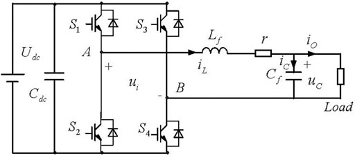
FIGURE 1. Topology and basic block diagram of the single-phase VSG.
The output active power Pe and reactive power Qe of single VSG can be calculated in the virtual two-phase system by sampling the output voltage uC and load current id (Suul et al., 2016). The virtual voltage and current will be 90° phase shifted in stationary conditions, and the vector amplitudes of the voltage and current are equal to the amplitude of the measured signals of the voltage and current. Then, the amplitude E0 and frequency ω of the output voltage reference can be obtained based on the VSG algorithm. The VSG algorithm includes active-frequency (P − f) and reactive-voltage (Q − U) control method by mimicing the traditional SG (Zhong and Weiss, 2011). In convenience of practical engineering applications, the second-order model of traditional SG is expressed as
where Tm and Te are the mechanical and electrical torques respectively, Pm and Pe are the mechanical and electrical power. J is the moment of inertia, Dp is the damping coefficient, ω is the rotor angular velocity, and ωref is the grid synchronous angular velocity. When the single-phase VSG operates in grid-connected mode, the value of ωref is the power grid frequency ωg which can be obtained through a phase-locked loop (PLL). When the VSG works in island mode, its value is equal to the microgrid reference frequency.
In order to mimic the primary frequency function of the SG, the primary frequency controller is substituted into the power frequency Eq. 1. The primary frequency controller can be expressed as
where kp is the P − f droop coefficient, Pref is the active power reference value. By combing Eqs 1–3 can be deduced as
From the above Eq. 3, it can be seen that the P − f controller of the VSG includes the characteristics of the droop control, moment of inertia and damp, which can enhance the stability of the power grid.
The Q − U controller of the VSG mimics the excitation regulation function of the SG to realize the drop characteristics of reactive power and voltage amplitude (Zhong and Weiss, 2011), and the equation can be expressed as:
where E0 and Eref are the actual output and rated voltage amplitude of the VSG respectively, kq is the Q − U droop coefficient, Qref and Qe are the reference and actual output reactive power respectively. However, according to Eq. 4, output reactive power Qe cannot achieve the zero-steady-error tracking of the reference reactive power Qref based on the proportional gain kq when the VSG operates in grid-connected mode. Therefore, a modified Q-U controller with integral term is obtained as
where ki is the integral coefficient of the Q-U controller. It should be noted that when the single VSG operates in grid-connected mode, Eq. 5 is used for achieving the zero-steady-error tracking of the reactive power, and the voltage amplitude Eref is equal to the grid voltage amplitude Ugm. When the VSG operates in island mode, Eq. 4 is used for Q-U controller, the reference reactive power Qref is equal to zero and the voltage amplitude Eref is equal to rated value.
Based on the analysis of the above mentioned section, the amplitude and frequency of the reference voltage Eref can be derived from the outer VSG power loop. In this section, the inner voltage regulation loop based on capacitor voltage and inductor current feedback achieves the tracking of the reference voltage, and the control block diagram is shown in Figure 2.
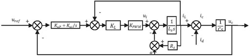
FIGURE 2. Block diagram of inner voltage regulation loop based on capacitor voltage and inductance current feedback.
The capacitor voltage transfer function uc(s) of the closed-loop system can be derived as
For simplicity, the resistance Rs is ignored because the value is small, and the voltage gain G(s) and output impedance Zo(s) can be respectively expressed as
and
where kup and kui are the proportional coefficient and integral coefficient of the capacitor voltage feedback loop controller respectively, kL is the proportional coefficient of the VSG inductor current feedback loop controller. According to Eq. 6, the output impedance of the system can be adjusted by changing the proportional and integral (PI) coefficient. Therefore, different output impedance can be obtained by selecting the appropriate PI parameters.
The detailed parameters of the whole system are given in Table 1 and Figure 3 shows bode diagram of output impedance Zo(s) with different PI parameters. As the value of the proportionality coefficient kup increase, it can be seen that the inductive proportion of the output impedance of the system gradually increases at the low frequency as shown in Figure 3A. However, large value of parameter kup will cause the instability of the system. Therefore, the parameter kup should be chosen based on the tradeoff the dynamic performance and the stability of the system. Figure 3B shows that the inductive proportion of the output impedance of the system gradually increases at the low frequency with the decreasing value of parameter kui, so a small value of parameter kui is preferred.
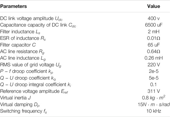
TABLE 1. System parameters.
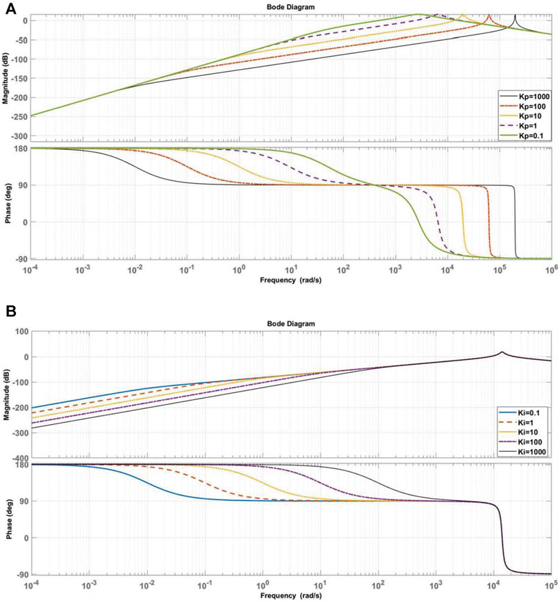
FIGURE 3. Bode diagram of output impedance Zo(s). (A) Bode diagram of with different parameter Kup. (B) Bode diagram of with different parameter Kui.
Although the inertia and damping are provided for the single-phase inverter by mimicking the traditional SG, the effects of virtual moment of inertia J, damping coefficient Dp, P − f and Q − U droop coefficients kp and kq on the stability of the VSG should be further analyzed. Next, a small signal model of the modified VSG strategy in grid-connected mode is established, and the influence of key parameters on the stability of the system is introduced.
Figure 4 shows the equivalent circuit when VSG operates in grid-connected mode. Where E and U represents the amplitude of the VSG output terminal voltage and the grid voltage respectively. Assuming that the phase angel of the power grid voltage is zero, δ is the phase angle of the VSG output voltage, the total impedance of the line between the VSG and the grid can be equivalent to Z∠α = R + jX, where α is the impedance angle. Therefore, the apparent power output of the VSG can be obtained,
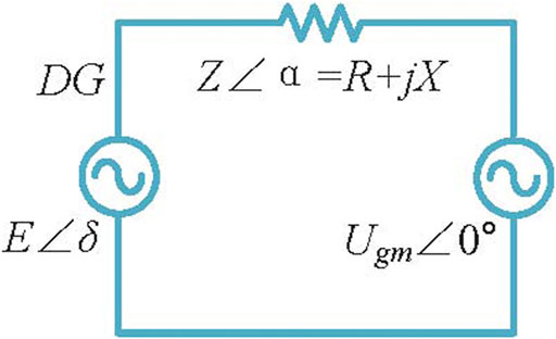
FIGURE 4. The equivalent circuit when VSG operates in grid-connected mode.
Assuming that the line impedance is mainly inductive and active power Pe and reactive power Qe can be derived as (Liu et al., 2020b)
The small signal model of the modified VSG can be obtained based on Eq. 8.
where KPE and KPδ are the partial derivative of active power Pe to voltage amplitude E and power angle δ respectively. KQE and KQδ are the partial derivative of reactive power Qe to voltage amplitude E and power angle δ respectively, and they can be expression as
As the output power of a single-phase VSG contains secondary power oscillations, a first-order low-pass filter is used to filter the secondary power oscillations contained in the output power. Small signal model of the output voltage amplitude and frequency of the VSG can also be obtained based on Eqs 1, 2, 5,
where, ωc is the cut-off frequency of the low-pass filter. Since
According to Eqs 8, 9, 12, it implies that
where
Eq. 15 describes the characteristics of the system with the small disturbances around the equilibrium point. Figure 5 shows the root locus diagram with different inertial J, damp coefficient Dp, droop parameters kp and kq.
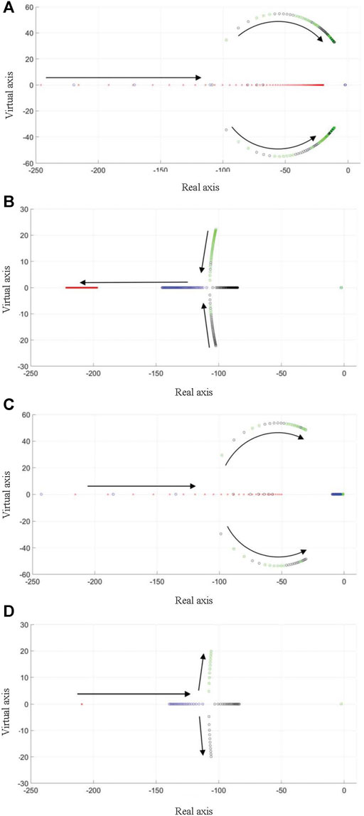
FIGURE 5. Root locus diagram. (A) with different inertia J(B) with different damp coefficient Dp. (C) with different droop parameter kp. (D) with different droop parameter kq.
It can be seen that with the increase of inertia J, droop parameters kp and kq, oscillation will appear and the system will become unstable. On the contrary, the VSG system will become more stable with the damp coefficient Dp increases.
In this section, an inductor current sensorless control method based on luenberger observer is proposed, and optimal pole assignment of the observer is also analyzed.
In order to reduce the sensor counts, a state observer is introduced here to evaluate the actual inductor current iL value. By the kirchhoff′s law of voltage and current, the single VSG system is modeled by
And the state-space mode can be derived by Eq. 17
where
and state variable x, input variable u, disturbance signal ω, and output variable y can be expressed as
As the load current id and capacitor voltage uC must be obtained to calculate the output active power Pe and reactive power Qe, an observed inductor current
and matrix A′ = A, C′ = C, B′ and the input variable
It is easy to prove that Eq. 19 satisfies the observability condition, that is
Therefore, the observed inductor current
where L is gain matrix. The block diagram of the observer is shown in Figure 6. By subtracting Eq. 20 from Eq. 19, the state error matrix is introduced:
where ex represents the state error matrix. When the eigenvalue of the matrix (A′ − LC′) is in the left side of the complex plate, the error of the observer will approach zero. Therefore, it is necessary to adjust the parameters of the state feedback matrix L.
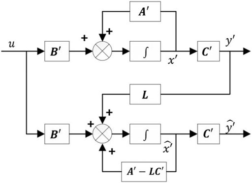
FIGURE 6. Block diagram of the observer.
In this section, the optimal pole assignment of the state observer is designed based on the optimal pole assignment principle (Lin, 2007). The distribution of the position of the characteristic root of the system in the complex plane determines the dynamic response speed and the degree of oscillation of the system, the farther the pole position of the transfer function is from the imaginary axis, the faster the dynamic response speed of the system.
Based on Eq. 19, the state variables of the capacitor voltage uC and the inductor current iL have the greatest impact on the system, the poles related to these two state variables are selected as the dominant poles. The original dominant pole and the expectation dominant pole after the optimal pole placement are shown in Figure 7. It is found that the original system is relatively close to the imaginary axis, the convergence speed of the system is slow, and it may cause instability of the system. However, the expectation pole is farther from the imaginary axis, which improves the dynamic response speed of the system. As the inductor current must be used for feedback control, the dynamic speed for the state observer should be faster than the controller, that is, its pole is generally 4 to 10 times that of the controller.
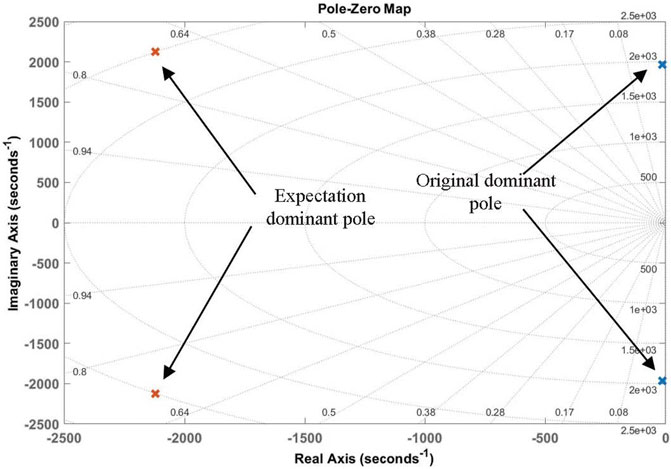
FIGURE 7. The original dominant pole and the expectation dominant pole.
Seamless switching is an important feature for safe operation of the VSG. Due to the deviation between the VSG output voltage and the grid voltage, seamless transfer requires pre-synchronization. As the output voltage and the power grid voltage can be measured, an orthogonal voltage signal must be obtained. In this paper, a phase-locked loop (SOGI-PLL) based on the second-order generalized integral is used to extract the grid voltage information (Matas et al., 2010; Liu et al., 2020a). The whole block diagram of the single-phase VSG is shown in Figure 8.
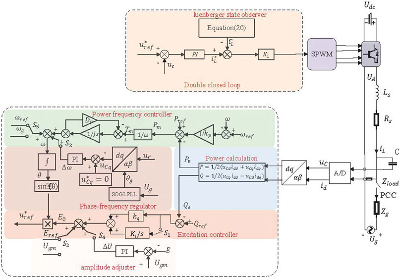
FIGURE 8. The whole block diagram of the single-phase VSG.
When VSG operates in island mode, the switch S2 is disconnected and the VSG works in P − f. The switch S5 is connected to the rated angular frequency ωref. The switches S1, S4 are disconnected and VSG works in Q − U, the switch S3 is connected to the rated voltage amplitude Eref. At this time, the output power of the VSG is the load power.
When the VSG operates in grid-connected mode, the switch S2 is disconnected and the switch S5 is connected to the grid and the reference frequency is angular frequency ωg. The switch S4 is disconnected, the switch S1 is connected to make the integration term works, the switch S3 is connected to the grid voltage amplitude Ugm.
When the VSG receives a signal that it needs to switch from grid-connected mode to island mode, since the VSG was previously in grid-connected operation and there is an inertia link in the VSG, the output voltage of the VSG theoretically will not have a transient sudden change at the moment of switching. At this time, the voltage, angular frequency, power reference value in the VSG control will automatically change to the given amount when the island is isolated, so the switch from grid-connected to island operation of the VSG can be completed without adding a complicated control strategy.
When the VSG switches from grid-connected mode to island mode, it starts the pre-synchronization process. At this time, the switches S2 and S4 are closed, the VSG gradually adjusts the phase, frequency and amplitude information of the output voltage in the island operation mode. When the grid-connected standard is reached, the pre-synchronization process finished and the grid-connected switch is closed. The reference power Pref and Qref in the VSG control loop will be replaced by the grid’s active power Pg and reactive power Qg. Due to the inertia of the VSG, the power output by the VSG will not undergo a step change, the VSG will complete the transfer from island to grid-connected with seamless switching feature.
In order to verify the effectiveness of the above-mentioned luenberger observed-based VSG strategy, a 3kVA simulation model based on the single-phase inverter was built. The key parameters are given in Table 1. The whole control diagram of the proposed modifier single-phase VSG control strategy is shown in Figure 8.
The single VSG operates in island mode initially, and the grid-connected signal is triggered at 0.35s, the island mode signal is triggered at 1.4s. In grid-connected mode, the VSG reference active power and reactive power is 3kW and 500var respectively.
Figure 9 shows the output active power Pe and reactive power Qe of single-phase VSG when operates in grid-connected mode and island mode. The simulation results demonstrate that when the single-phase VSG switches between the two operating modes, there is no obvious power mutation and the output power of the VSG can reach the reference power in grid-connected mode.

FIGURE 9. The output active power Pe and reactive power Qe of the single-phase VSG.
The seamless transfer capability of the single-phase VSG based on the proposed method is also verified by simulation results as shown in Figure 10. Figure 11A shows the waveform of capacitor voltage uC, power grid voltage Ug, and the load current id when the VSG operates in island mode. As the initial phase difference between the power grid voltage and capacitor voltage uC is 30°, the voltage deviation Δu between the grid voltage and the inverter output voltage exists.
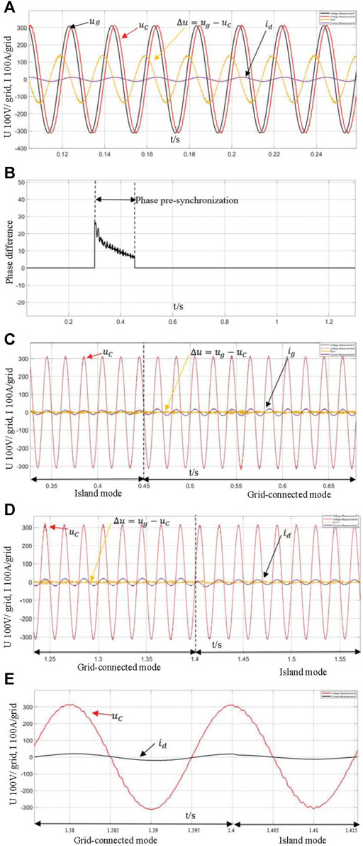
FIGURE 10. Seamless transfer of the single-phase VSG. (A) Simulation waveform of capacitor voltage and load current in island mode. (B) Pre-synchronization process. (C) Simulation waveforms of capacitor voltage and load current from island mode to grid-connected mode. (D) Simulation waveforms of capacitor voltage and load current from grid-connected mode to island mode. (E) partial enlarged view of capacitor voltage and load current (grid-connected mode to island mode).
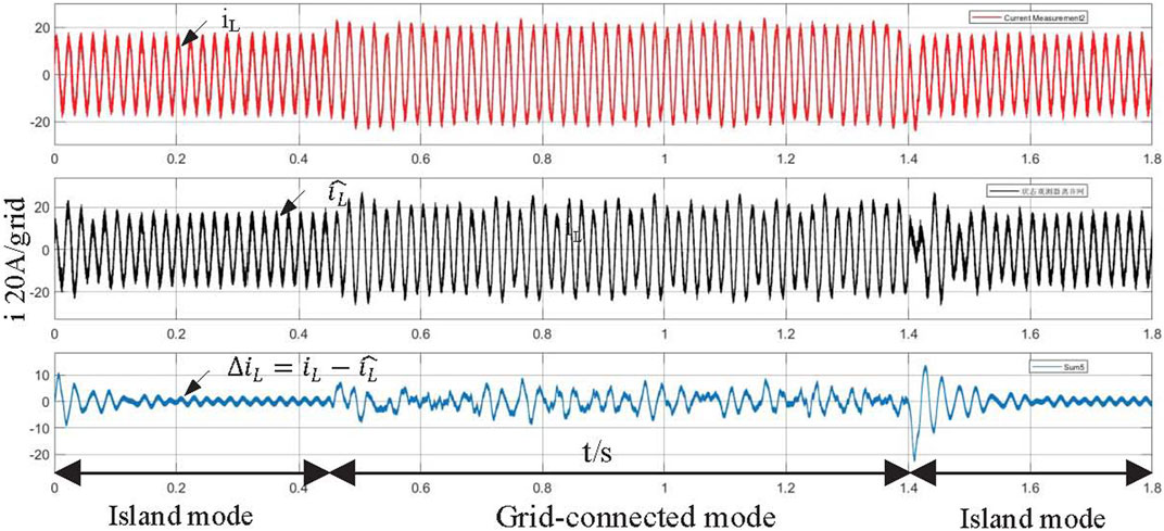
FIGURE 11. Simulation waveform of real inductor current iL, observed inductor current
Figure 10B shows the pre-synchronization process when single-phase VSG switches from island mode to grid-connected mode. At time 0.3s, the trigger signal enables, and the pre-synchronization process starts, the phase angle difference Δθ between the VSG output voltage phase and the grid voltage phase gradually decreases. When the phase difference Δθ is less than the threshold value of 3° at time 0.45s, the pre-synchronization process ends, and the VSG switches to the grid-connected mode.
Figure 10C,D shows the voltage and current waveforms of seamless transfer between the island mode and grid-connected mode at time 0.45 and 1.4 s respectively. Simulation results demonstrate that smooth switching between island mode and grid-connected mode can be achieved, and the inrush current is small. Figure 10E shows the partial enlarged view of VSG voltage uC and load current id, it demonstrates that the voltage sags is small when VSG switches from grid-connected mode to island mode.
Figure 11 shows the simulation waveform of the observed inductor current iL and the actual inductor current iL, and ΔiL is the deviation between them. The gain matrix L = [−500,−500,−500,−500,−500,−500,−500,−500,−500,−500]T. It can be seen that the estimation error of the observer is small and the dynamic response speed is fast when the VSG operates in grid-connected mode and island mode.
A 3kW single-phase full-bridge inverter prototype is built to verify the feasibility of the proposed control method. The main parameters of the system use are shown in Table 1. The performance of the proposed control strategy is validated by dSPACE SCALEXIO system for real-time implementation, as shown in Figure 12. The prototype is mainly composed of single-phase full-bridge inverter main circuit, A/D sampling circuit, DSPACE transfer board, auxiliary switching power supply and host computer. The output voltage and current waveforms are displayed through the oscilloscope YOKOGAWA-DLM2024. The DC side voltage source adopts programmable DC power supply model Chroma62150H-1000s, and the AC power supply adopts the programmable AC power supply model Chroma61845.
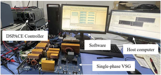
FIGURE 12. Experimental prototype.
Figure 13 shows the experimental results of seamless transfer process between the island and grid-connected based on the proposed control strategy. The output voltage uC and load current id experimental waveform is demonstrated in Figure 13A when the VSG is switched between grid-connected and island modes. The output voltage almost unchanged and the grid-connected current fluctuates very little when the operating mode of the single-phase VSG changes. High performance of dynamic waveform can be achieved. Figure 13B,C show the partial enlarged experimental waveform of the dynamic process between the island mode and the grid-connected mode, and the voltage waveform changes little throughout the process. Figure 13D shows the output active power Pe and reactive power Qe of the VSG reached 3kW and 500var respectively when connected to the power grid, which is consistent with the reference active and reactive power.
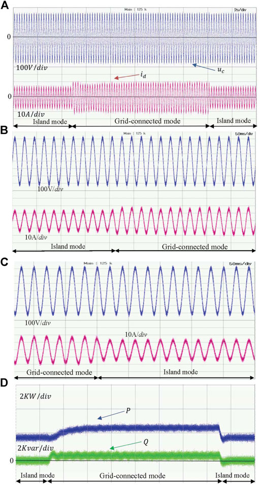
FIGURE 13. Experimental waveform of seamless transfer. (A) Experimental waveforms of single-phase VSG capacitor voltage and load current based on seamless transfer. (B) Partial enlarged experimental waveform of the dynamic process from island mode to grid-connected mode. (C) Partial enlarged experimental waveform of the dynamic process from grid-connected mode to island mode. (D) Experimental waveform of single-phase VSG output power.
Figure 14 shows the experimental waveforms of the actual inductor current iL and the observed current
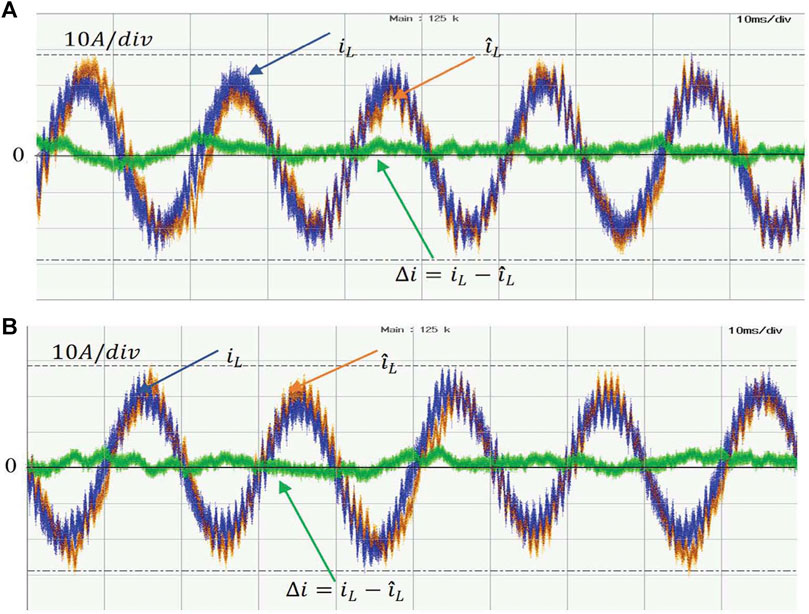
FIGURE 14. Experimental waveforms of real inductor current iL, observed inductor current
A modifier VSG control strategy for single-phase inverter-interfaced microgrid application is proposed in this paper, and it can realize the seamless transition between the island mode and grid-connected mode. The effectiveness and feasibility of the proposed control method is verified by the simulation and experimental results. The main contribution of the proposed modifier VSG control strategy can be summarized as follows: 1) It can achieve zero-steady-tracking error of the output reactive power by adding Q-U integral term in grid-connected mode. 2) The proposed control method can reduce the sensor of inductor current based on the luenberger observer. 3) The high performance of the single-phase inverter based on the proposed modifier VSG method can be obtained in island mode, grid-connected mode and the transient process.
The original contributions presented in the study are included in the article/supplementary material, further inquiries can be directed to the corresponding authors.
ZZ is in charge of the method calculation, paper writing and experiment. JW and DX is in charge of literature review, experimental setup, and proofread the manuscript. LZ is in charge of the experimental setup. XT is in charge of the experimental guidance. All authors contributed to the article and approved the submitted version.
This work was supported in part by the Teaching Quality and Teaching Reform Project of Guangdong Province under Grant Nos. PX-3218216 and 201801283006, in part by the Dongguan Social Science and Technology Development Project under Grant Nos. 2019507140826 and Grant 2020507140141, and in part by Enterprise Sci-tech Commssioner of Guangdong province under Grant No. GDKTP2020013700.
DX was employed by the Guangdong HYNN Technologies Co., Ltd.
The remaining authors declare that the research was conducted in the absence of any commercial or financial relationships that could be construed as a potential conflict of interest.
All claims expressed in this article are solely those of the authors and do not necessarily represent those of their affiliated organizations, or those of the publisher, the editors and the reviewers. Any product that may be evaluated in this article, or claim that may be made by its manufacturer, is not guaranteed or endorsed by the publisher.
Alcala, J. M., Castilla, M., De Vicuña, L. G., Miret, J., and Vasquez, J. C. (2010). Virtual Impedance Loop for Droop-Controlled Single-phase Parallel Inverters Using a Second-Order General-Integrator Scheme. IEEE Trans. Power Electron. 25, 2993–3002. doi:10.1109/TPEL.2010.2082003
Beck, H. P., and Hesse, R. (2007). “Virtual Synchronous Machine,” in 2007 9th International Conference on Electrical Power Quality and Utilisation (Barcelona, Spain: IEEE), 1–6. doi:10.1109/epqu.2007.4424220
Blaabjerg, F., Teodorescu, R., Liserre, M., and Timbus, A. V. (2006). Overview of Control and Grid Synchronization for Distributed Power Generation Systems. IEEE Trans. Ind. Electron. 53, 1398–1409. doi:10.1109/TIE.2006.881997
Canziani, F., Vargas, R., and Gastelo-Roque, J. A. (2021). Hybrid Photovoltaic-Wind Microgrid with Battery Storage for Rural Electrification: A Case Study in Perú. Front. Energ. Res. 8, 1–11. doi:10.3389/fenrg.2020.528571
Cheng, C., Xie, S., Xu, J., and Qian, Q. (2021). State-and-Disturbance-Observer-Based Current Control Scheme for LCL-Filtered Single-phase Grid-Tied Inverters under Non-ideal Conditions. IEEE J. Emerg. Sel. Top. Power Electron. 6777, 1. doi:10.1109/JESTPE.2021.3067466
Hinsui, T., and Sangtungtong, W. (2019). “Voltage Observer-Based Control for Single-phase Grid-Connected Pv Inverter,” in 2019 7th International Electrical Engineering Congress (iEECON), March 2019. (Hua Hin, Thailand: IEEE), 1–4. doi:10.1109/iEECON45304.2019.8938957
Latham, J., Mohebbi, M., and McIntyre, M. L. (2017). Output Feedback Control of a Single Phase Voltage Source Inverter Utilizing a Variable Structure Observer. Proc. Am. Control. Conf. 40292, 4081–4086. doi:10.23919/acc.2017.7963581
Li, D., Zhu, Q., Lin, S., and Bian, X. Y. (2017). A Self-Adaptive Inertia and Damping Combination Control of VSG to Support Frequency Stability. IEEE Trans. Energ. Convers. 32, 397–398. doi:10.1109/TEC.2016.2623982
Li, H., Zhang, X., Shao, T., and Zheng, T. Q. (2019). Flexible Inertia Optimization for Single-phase Voltage Source Inverter Based on Hold Filter. IEEE J. Emerg. Sel. Top. Power Electron. 7, 1300–1310. doi:10.1109/jestpe.2018.2865214
Liu, B., An, M., Wang, H., Chen, Y., Zhang, Z., Xu, C., et al. (2020a). A Simple Approach to Reject DC Offset for Single-phase Synchronous Reference Frame PLL in Grid-Tied Converters. IEEE Access 8, 112297–112308. doi:10.1109/access.2020.3003009
Liu, B., Wu, T., Liu, Z., and Liu, J. (2020b). A Small-AC-Signal Injection-Based Decentralized Secondary Frequency Control for Droop-Controlled Islanded Microgrids. IEEE Trans. Power Electron. 35, 11634–11651. doi:10.1109/tpel.2020.2983878
Lou, G., Yang, Q., Gu, W., Quan, X., Guerrero, J. M., and Li, S. (2021). Analysis and Design of Hybrid Harmonic Suppression Scheme for VSG Considering Nonlinear Loads and Distorted Grid. IEEE Trans. Energ. Convers. 8969, 1. doi:10.1109/tec.2021.3063607
Monfared, M., Golestan, S., and Guerrero, J. M. (2014). Analysis, Design, and Experimental Verification of a Synchronous Reference Frame Voltage Control for Single-phase Inverters. IEEE Trans. Ind. Electron. 61, 258–269. doi:10.1109/TIE.2013.2238878
Qazi, H. S., Zhao, T., Liu, N., Wang, T., and Ullah, Z. (2021). Optimal Operation of Isolated Micro-grids-cluster via Coalitional Energy Scheduling and Reserve Sharing. Front. Energ. Res. 9, 1–14. doi:10.3389/fenrg.2021.629131
Shao, T., Jia, P., Zheng, P., Zheng, T. Q., Wang, J., Li, H., et al. (2019). A Robust Power Regulation Controller to Enhance Dynamic Performance of Voltage Source Converters. IEEE Trans. Power Electron. 34, 12407–12422. doi:10.1109/tpel.2019.2906057
Suul, J. A., DArco, S., and Guidi, G. (2016). Virtual Synchronous Machine-Based Control of a Single-phase Bi-directional Battery Charger for Providing Vehicle-To-Grid Services. IEEE Trans. Ind. Applicat. 52, 3234–3244. doi:10.1109/TIA.2016.2550588
Teng, Q., Xu, D., Yang, W., Li, J., and Shi, P. (2021). Neural Network-Based Integral Sliding Mode Backstepping Control for Virtual Synchronous Generators. Energ. Rep. 7, 1–9. doi:10.1016/j.egyr.2020.11.032
Tran, T. V., and Kim, K.-H. (2020). Frequency Adaptive Grid Voltage Sensorless Control of LCL-Filtered Inverter Based on Extended Model Observer. IEEE Trans. Ind. Electron. 67, 7560–7573. doi:10.1109/TIE.2019.2944075
Valinejad, J., Marzband, M., Korkali, M., Xu, Y., and Saad Al-Sumaiti, A. (2020). Coalition Formation of Microgrids with Distributed Energy Resources and Energy Storage in Energy Market. J. Mod. Power Syst. Clean Energ. 8, 906–918. doi:10.35833/MPCE.2019.000116
Van, T. V., Visscher, K., Diaz, J., Karapanos, V., Woyte, A., Albu, M., Bozelie, J., Loix, T., and Federenciuc, D. (2010). “Virtual Synchronous Generator: An Element of Future Grids,” in IEEE PES Innovative Smart Grid Technologies Conference Europe (Europe: ISGT), 1–7. doi:10.1109/ISGTEUROPE.2010.5638946
Wang, F., Zhang, L., Feng, X., and Guo, H. (2018). An Adaptive Control Strategy for Virtual Synchronous Generator. IEEE Trans. Ind. Applicat. 54, 5124–5133. doi:10.1109/TIA.2018.2859384
Wang, T., O'Neill, D., and Kamath, H. (2015). Dynamic Control and Optimization of Distributed Energy Resources in a Microgrid. IEEE Trans. Smart Grid 6, 2884–2894. doi:10.1109/TSG.2015.2430286
Zhang, L., Wang, F., Guo, H., Feng, X., Du, Y., and Su, J. (2017). “Perturbation Influences of Parameters on Dynamic Performance of a Virtual Synchronous Generator,” in Proceedings IECON 2017 - 43rd Annual Conference of the IEEE Industrial Electronics Society, October 2017, (Beijing, China: IEEE), 1405–1410. doi:10.1109/IECON.2017.8216239
Zhang, Z., Fan, M., Dai, Z., Zhang, J., Yang, Y., and Chen, X. (2021). Multi-consecutive-samples Based Frequency Estimation for Single-phase Systems under Odd-, Even-Order Harmonics and DC Offsets. Int. J. Electr. Power Energ. Syst. 128, 106724. doi:10.1016/j.ijepes.2020.106724
Zhao, Y., Chai, J., Wang, S., and Sun, K. (2017). Instantaneous Power Calculation Based on Intrinsic Frequency of Single-phase Virtual Synchronous Generator. J. Mod. Power Syst. Clean. Energ. 5, 970–978. doi:10.1007/s40565-017-0272-5
Zhong, Q.-C., and Weiss, G. (2011). Synchronverters: Inverters that Mimic Synchronous Generators. IEEE Trans. Ind. Electron. 58, 1259–1267. doi:10.1109/TIE.2010.2048839
Keywords: VSG, luenberger state observer, microgrid, seamless switching, single-phase
Citation: Zhang Z, Wu J, Zheng L, Xie D and Tang X (2021) An Inductor Current Sensorless Control Strategy Based on Modified VSG Method for Single-Phase Microgrid Application With Seamless Transfer Capability. Front. Energy Res. 9:752422. doi: 10.3389/fenrg.2021.752422
Received: 03 August 2021; Accepted: 13 September 2021;
Published: 01 October 2021.
Edited by:
Xiaoshun Zhang, Shantou University, ChinaCopyright © 2021 Zhang, Wu, Zheng, Xie and Tang. This is an open-access article distributed under the terms of the Creative Commons Attribution License (CC BY). The use, distribution or reproduction in other forums is permitted, provided the original author(s) and the copyright owner(s) are credited and that the original publication in this journal is cited, in accordance with accepted academic practice. No use, distribution or reproduction is permitted which does not comply with these terms.
*Correspondence: Zhi Zhang, emhhbmd6QGRndXQuZWR1LmNu; Di Xie, eGllZGkwODEzQGFsaXl1bi5jb20=
Disclaimer: All claims expressed in this article are solely those of the authors and do not necessarily represent those of their affiliated organizations, or those of the publisher, the editors and the reviewers. Any product that may be evaluated in this article or claim that may be made by its manufacturer is not guaranteed or endorsed by the publisher.
Research integrity at Frontiers
Learn more about the work of our research integrity team to safeguard the quality of each article we publish.