 Tianyi Zhang1
 Haifeng Wang2*
- 1State Key Laboratory for Alternate Electrical Power System with Renewable Energy Sources, North China Electric Power University, Beijing, China
- 2College of Electrical Engineering, Sichuan University, Chengdu, China
With the continuous growth in the amount of wind power accessed by the AC grid, the impact of the grid connection of wind-power generators with the power system has gradually increased. In this study, the subsynchronous oscillation of a synchronous generator (SG) shaft caused by the integration of direct-drive permanent-magnet synchronous generators (PMSGs) was investigated. The mechanism governing the effect of the connection strength between the PMSG and AC power system on the stability of the generator shaft system was analyzed based on the complex torque coefficient method. When the connection strength between the PMSG and AC power system weakens, the same voltage variation that occurs at the point of common coupling of the PMSG stimulates more intense power fluctuations in the PMSG, and the electrical damping injected by the PMSG into the SG increases considerably. This may cause the oscillation mode dominated by the generator shaft system to move to the right half of the complex plane, thereby reducing the stability of the generator shaft system. In addition, the evaluation process of the influence of the PMSG on the SG shaft system was summarized, and the proposed method can determine the stability of the AC power system after the integration of the PMSG. Finally, the effectiveness of the proposed method was validated via study cases, and conclusions were drawn. This method is expected to serve as a useful tool for the risk assessment of subsynchronous oscillations in wind farms.
Introduction
Wind power is a clean and renewable energy source that has the potential to be harnessed on a large scale. Hence, wind-power generators have been developed rapidly in recent years (Zhang et al., 2021; Liu et al., 2021). However, the dynamics of AC power systems are also considerably affected by the large-scale integration of wind-power generators. The dynamic interaction between wind power and the AC grid can result in oscillation instability in the power system (Xiong and Zhuo, 2013; Xiong et al., 2020; Du et al., 2021). On July 1, 2015, subsynchronous oscillations (SSOs) occurred in a wind farm containing direct-drive permanent-magnet synchronous generators (PMSGs) in Xinjiang Uygur Autonomous Region, China, and the SSOs spread to a thermal power plant located 300 km away from the wind farm, causing three synchronous generators (SGs) to be cut off to ensure torsional vibration protection and resulting in a power loss of 1280 MW (Xie et al., 2017). In order to solve the off-grid accident caused by subsynchronous oscillations, A lot of research has been done from different ways Zhou et al. (2021).
Nasiri and Hansen et al. conducted research on improving system stability from the perspective of improving the low voltage ride through (LVRT) capability of PMSGs. Nasir et al. (2015) summarized performances of different LVRT capability enhancement methods and use of some LVRT capability enhancement methods in PMSG based wind turbine which are applied in other kind of wind power generators. The enhancement methods were compared by simulation analysis, which laid a good foundation for the determination of the future research direction. Nasiri and Mohammadi (2016) presents solutions by improve back-to-back converter’s controllers and limit active power to maintain the peak current of the grid side inverter in a safe range during different asymmetrical grid faults. This study improves the stability of the grid side converter when asymmetric faults occur and provides a new idea for the stable operation of the power system. Hansen and Michalke (2009) presented a control strategy which enhances the LVRT capability of wind turbines during grid faults. These beneficial studies improve the LVRT capability of wind turbines and play an important role in the stable operation of wind farms in the case of faults.
At the same time, the influence of large-scale wind power access on the stability of synchronous generator shaft in AC power system has been studied from the perspective of mechanism analysis. Zhang et al. (2018) studied the impact of PMSGs on the oscillation stability of a power system based on an impedance model and found that a PMSG behaves as a negative resistor at the SSO frequency when the parameters of the converter control system are set improperly. Based on open-loop modal resonance, Du et al. (2017b) explained the reasons for the generation of SSOs, which were induced by the improper setting of the parameters of the converter control systems of the PMSG. That is, an inappropriate set of control parameters can cause an open-loop oscillation mode (OLOM) of the PMSG to move toward an OLOM of the SG shaft, thus resulting in a reduction in the damping of the closed-loop oscillation mode of the SG shaft. In addition to an improper set of control parameters, a weak grid connection is another key factor affecting the oscillation stability of a PMSG-integrated power system. Case studies conducted by Jiang et al. (2000) showed that the oscillation mode of the phase-locked loop (PLL) or direct-current capacitor voltage control outer loop (DCVL) can move toward the right half of the complex plane as the grid connection weakens. Alawasa et al. (2013) studied the SSO incident that occurred in Xinjiang and found that a weak grid connection caused by a PMSG wind farm is one of the decisive factors governing the SSO of a non-series-compensated power system. Furthermore, Dong et al. (2017) demonstrated that as the short circuit ratio (SCR) decreases, some specific SSO modes of the PMSG wind farm can move to the right of the complex plane, and when the SSO modes are close to the oscillation modes of the SG shaft, subsynchronous torsional excitation can occur. However, current studies have only confirmed that a weak grid connection can deteriorate the stability of the power system under specific scenarios, and general conclusions on the amplification effect of a weak grid connection on the dynamic interaction between the wind farm and AC power system still need to be drawn (Du et al., 2019b).
The methods used to analyze the SSO of wind-power-integrated systems include mode analysis and frequency domain analysis (Piyasinghe et al., 2014; Fu et al., 2021a; Fu et al., 2021b). When studying the SSO of a multimachine power system induced by the integration of wind-power generators using mode analysis, the wind farm and multimachine power system should be considered as a combined entity and the stability of the system should be judged according to the eigenvalues of the closed-loop state-space matrix of the combined entity. The results obtained using mode analysis have high accuracy. However, the computational burden is high when a large number of wind turbine generators (WTGs) and SGs are present in the system. In addition, the results can only provide conclusions pertaining to stability judgment and cannot reveal the mechanism behind the instability caused by the integration of wind-power generators. Frequency domain analysis includes impedance-model-based analysis and the complex torque coefficient method, which reveal the mechanism of the SSO in terms of negative resistance and negative damping, respectively, with a clear physical meaning. However, both the methods only provide sufficient nonessential conditions for the stability of the system, and thus, the stability judgment can be conservative. In the SSO analysis based on the complex torque coefficient method, the researched system is divided into two subsystems: a mechanical subsystem and an electrical subsystem. The stability of the system can be assessed according to the sum of the real parts of two equivalent coefficients obtained by calculating the equivalent mechanical torque coefficient and equivalent electromagnetic torque coefficient at a certain torsional vibration frequency. If the sum is greater than zero, the torsional mode can be determined to be stable (Canay, 1982). In recent years, the complex torque coefficient method has been used in the SSO analysis of wind-farm-integrated power systems owing to its advantages, i.e., simplicity of establishing the theoretical model and the ability to reflect the damping and frequency characteristics of the mechanical and electrical subsystems in the SSO frequency band (Gao et al., 2015; Du et al., 2019a). Considering the limitations of the traditional complex torque coefficient method in the stability analysis of a multimachine power system (Xu, 2000), an improved complex torque coefficient method is proposed in this paper by combining the frequency domain analysis and mode analysis. Wang et al. (2021) proposed an improved complex torque coefficient method, which combined frequency domain analysis with mode analysis, to analyze the dynamic interaction between the fan and generator from the perspective of the damping mechanism. However, this study did not analyze the influence of line parameter variations of AC systems on the dynamic interaction between grid-connected wind farms and multigenerator power systems. In view of the possible amplification effect of line parameter variations on the dynamic interaction, it is necessary to carry out research on the influence of the connection strength on AC system parameters to clarify the physical meaning of the SSO of the synchronous shaft system caused by multiple wind-farm grid connections. In the present study, an index to evaluate the stability of SSO was established under the condition of a weak connection of a wind farm to a power grid, and the mechanism of SSO caused by the weak connection was revealed. The results of this study are expected to serve as a theoretical basis for subsequent measures undertaken to suppress SSO.
The remainder of this paper is organized as follows. In the next section, the linearized state-space model of a multimachine power system with multiple integrated PMSGs is presented. In Section Stability Criterion for Multiple-Wind-Farm-Integrated Power System Based on Improved Complex Torque Coefficient Method, methods and indicators based on the improved complex torque coefficient method are proposed to evaluate the risk of SSO of the shaft of the multimachine power system considering the impact of the integration of PMSG wind farms. In addition, the mechanism of the shaft oscillation of the multimachine power system caused by the PMSG wind farm under a weak grid connection is revealed. Section Study Cases presents the demonstration of the effectiveness of the proposed method via study cases and the analysis of the interaction process between multiple wind farms and a multimachine power system. The final section summarizes the conclusions of the study.
Linearized State-Space Model of Multimachine Power System With Multiple Integrated Permanent-Magnet Synchronous Generators
Figure 1 shows the configuration of a power system with multiple integrated PMSGs. In the figure,
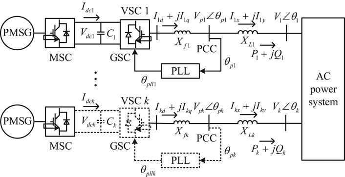
FIGURE 1. Configuration of power system with multiple integrated PMSGs (MSC: machine-side converter; GSC: grid-side converter).
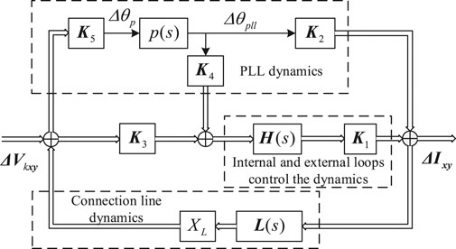
FIGURE 2. Diagram showing dynamic process of GSC of kth PMSG considering PLL.
According to Figure 2, the transfer function of the internal and external loop control dynamics, PLL dynamics, and connected circuit dynamics of the network-side VSC can be considered as shown in Eq. 1.
From Figure 2, the transfer function of the grid-side converter (GSC) considering the dynamics of the PLL and the connecting line can be obtained as
Let us denote
From (1), the relationship between the output power and terminal voltage of the PMSG is
where.
From (3), it can be seen that under a certain frequency, as XL increases from 0, FX (s) increases from 1, causing stronger power fluctuations under the same voltage fluctuation ΔVxy. In particular, when the denominator of FX (s) approaches 0, ΔPk and ΔQk approach infinity, which can result in the loss of the stability of the system. Thus, an increase in XL can increase the intensity of the dynamic interaction between the grid-connected PMSG wind farm and the AC power system and may affect the stability of the wind-farm-integrated power system. Therefore, FX (s) can reflect the impact of the change in XL on the dynamic response strength of the PMSG and the effect of the PMSG on the stability of the power system after being connected to the grid. To further study the relationship between XL and the stability of the PMSG-integrated power system, FX (s) is considered separately, and the transfer function of the kth PMSG can be written as
where
Based on (4), the transfer functions of N PMSGs can be written as
where ΔVw = [ΔV1 ΔV2 ··· ΔVn]T, ΔPw = [ΔP1 ΔP2 ··· ΔPn]T, and ΔQw = [ΔQ1 ΔQ2 ··· ΔQn]T.
Referring to the mathematical model of the multiple-PMSG system and taking ΔPw and ΔQw as inputs and ΔVw as the output, the state-space model of the multimachine power system can be written as
where ΔXs is the vector of the state variables of the multimachine power system and As is the linearized state-space matrix of the system. BP, BQ, Cs, DP and DQ are coefficient matrices. By performing Laplace transform in (6), the open-loop transfer function of the multimachine power system can be obtained as
The characteristic equation of the multimachine power system with multiple integrated PMSGs can be established from Eqs. 5–7. To derive the analytical expression for the complex torque coefficient of the SG shaft, the SGs in the multimachine power system are further divided into two interconnected open-loop subsystems: the electrical and mechanical subsystems. The output and input of the mechanical subsystem are the vector of the rotor angular displacement increments of the SGs in the system, Δδ = [Δδ1 Δδ2 ··· Δδn]T and the vector of the torque increments of the SGs ΔT = [ΔT1 ΔT2 ··· ΔTn]T, respectively. Each of the elements in ΔT is constituted by the superposition of the corresponding items of the torque column vectors ΔTe, ΔTwP, and ΔTwQ, where ΔTe = [ΔTe1 ΔTe2 ··· ΔTen]T is the torque vector of the electromagnetic torque change of each SG caused by the internal electrical quantity of the SGs and
where ΔTwP and ΔTwQ are the torque vectors corresponding to the torques supplied by the active and reactive power injected by the h wind farms, respectively. Then, the state-space model of the mechanical subsystem of the multimachine power system can be obtained as
where ΔXm is the vector of the state variables of the shafts of the SGs. Am, Bm, and Cm are the state-space matrix, input matrix, and output matrix, respectively.
The input and output of the electrical subsystem are Δδ and ΔT, respectively, and the corresponding state-space model is
where ΔXe is the vector of the electrical parts of the SGs and the external system. Ae, Be, and Ce are the state-space matrix, input matrix, and output matrix, respectively.
According to (9) and (10), the transfer functions of the mechanical and electrical subsystems are
Thus, the closed-loop interconnected mode of the mechanical and electrical subsystems of the multimachine power system with N integrated PMSGs can be obtained as shown in Figure 3.
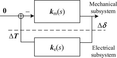
FIGURE 3. Closed-loop interconnected mode of mechanical and electrical subsystems of power system with N integrated PMSGs.
The model shown in Figure 3 and expressed in (11) is the basis for the study of the stability criterion based on the improved complex torque coefficient method for a multiple-PMSG-integrated power system.
Stability Criterion for Multiple-Wind-Farm-Integrated Power System Based on Improved Complex Torque Coefficient Method
Decomposition of Multimachine Power System
To obtain the damping torque coefficients of the N PMSGs fed into each SG according to the definition of the complex torque coefficient method, the electromagnetic torque increment of each SG in the AC power system should be expressed according to the rotor angular displacement increment (or angular velocity increment) as in the case of a linear relationship (Canay, 1982). Because the power angle characteristic of any SG in a multimachine power system is a multivariable function of the relative rotor angle between an SG and the other SGs, the input torque increment of the mechanical subsystem of each SG cannot be directly expressed as the linear combination of its rotor angular displacement increment and angular velocity increment (Xu, 2000). Therefore, the transfer functions in (11) should be organized further.
First, the shaft of the SG under study can be decoupled and the torsional vibration mode of the shaft under study can be separately expressed, as described by Ni et al. (2002). There are N-1 subsynchronous torsional vibration modes and one rigid-body resonant low-frequency mode in the N-mass shaft system, where the common mode usually behaves as a low-frequency oscillation mode and can be ignored. Assuming that the kth SG in the system has shaft torsional vibration modes, the shaft system can be transformed into lk equivalent rotors with decoupled modes. Each equivalent rotor contains only one independent mode, and the external torque ΔTk is uniformly added to each equivalent rotor.
The superscript (m) denotes the decoupling mode, and the decoupling equivalent rotor angular displacement vector of the shaft system of the kth SG can be obtained as
where
Combining (7) and (12), the decomposed representation of the state-space model of the AC system can be expressed as
where ΔXe is the vector of the state variables in ΔXs except Δδk and Δωk, and the matrices before the state variable vectors and input and output vectors are the corresponding coefficient matrices.
Then, the closed-loop interconnected system model of the multiple-PMSG-integrated power system corresponding to the shaft oscillation mode λki after the decoupling of the shaft systems of the SGs can be obtained, as shown in Figure 4.
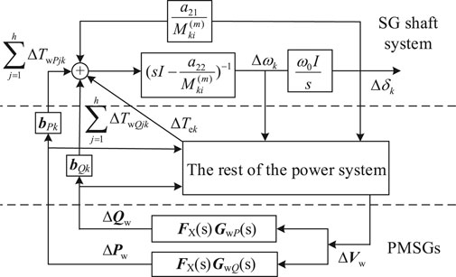
FIGURE 4. Interconnected multimachine power system with multiple integrated PMSGs.
Calculation of Damping Torque
From Figure 4, it can be seen that the electromagnetic torque fed into the kth SG in the AC power system consists of three parts:
As indicated in Figure 5, the effect of the torques of the N PMSGs on the ith shaft oscillation mode of the kth SG can be divided into two parts. One part is directly applied to the rotor of the SG via the output active and reactive power ΔPw and ΔQw of the multiple PMSGs, i.e., the last two terms in (14). The other part acts on Tk via the influence of ΔPw and ΔQw on the rest of the state variables of the SGs in the system; this part is included in the first term in (14). To reflect the interaction between the SGs and PMSGs, the sum of the second part is denoted as ΔTwk.
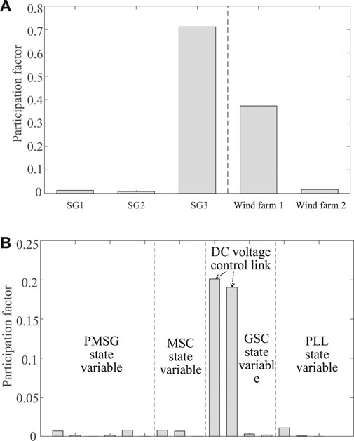
FIGURE 5. Participation factors of λ1: (A) participation factors of three SGs and two wind farms to λ1 and (B) participation factors of PMSGs in wind farm one to λ1.
Then, the transfer functions from ΔPw to ΔTwkP and ΔQw to ΔTwkQ, i.e., GPk(s) and GQk(s), can be obtained as
GPk(s) is a row vector corresponding to the N elements in the column vector ΔPw, and GQk(s) is a row vector corresponding to the N elements in the column vector ΔQw. Substituting (16) into the linearization state equation of the PMSGs expressed in (7), the relationship between the input variables of the PMSGs and the feed electromagnetic torque ΔTwk of the kth SG can be derived as
As derived by Du et al. (2016), for the ith shaft oscillation mode λki of the kth SG, the transfer function GUk from the angular velocity variable of the SG Δωk to the terminal voltages of the h wind farms
where
The real part of Gwk (λki) is the electrical damping torque coefficient injected by the PMSGs to the kth SG and is denoted as Dwk. From (19), it can be seen that Gwk(λki) is proportional to
Stability Criterion
We denote the ith shaft oscillation mode of the kth SG before the N PMSGs are connected to the grid as λki0, which can be obtained through the eigenvalue analysis of As. After the N PMSGs are connected to the grid, the damping torque coefficient Dwk injected into the AC system by the N PMSGs can be used to characterize the dynamic interactions between the shaft system of the kth SG and the N PMSGs. The sensitivity of λki to Dwk can be defined as
Then, the subsynchronous dynamic interaction index can be obtained as
From this, the vibration mode of the shaft system of the multimachine power system after the N PMSGs are integrated can be calculated as
From (3) and (21), it can be seen that when
The process to evaluate the risk of the SSO of the shaft system of the SGs in an AC power system with N integrated PMSGs by the improved complex torque coefficient method can be summarized as follows:
1) Establish the mechanical–electrical coupling model of the AC power system with N integrated PMSGs, and calculate the initial value of the ith shaft oscillation mode of the kth synchronous machine in the AC system before the N PMSGs are integrated, i.e., λki0.
2) Decouple the shaft of each SG in the system and establish the model of the vibration mode (λki) of the shaft system to be studied after the N PMSGs are integrated, as shown in Figure 5. Calculate the sum of the damping torque coefficients of each PMSG up to the kth SG, Dwk, corresponding to the oscillation mode obtained according to (19) to provide a prediction for the stability of the system.
3) Calculate the sensitivity of λki to Dwk and Ski. If the real part of Ski is greater than 0, the integration of the PMSG will deteriorate the stability of the system, and the stability of the system under these circumstances can be assessed based on (22). If the real part of λki is smaller than 0, that is, after the integration of the PMSG, the oscillation mode will still be in the left half of the complex plane and the shaft system of the SG will be stable. If the real part of λki is greater than or equal to 0, the shaft system will suffer from SSO or the system will be in a critical stable state.
In this section, the process and indicators for evaluating the risk of the SSO of the shaft system of the SG considering the impact of the integration of PMSGs are proposed based on the improved complex torque coefficient method. Compared to the traditional method of eigenvalue analysis, the proposed method calculates eigenvalues and participation factors on subsystems with lower orders, and hence, the computational burden is reduced. In addition, the proposed method can analyze the dynamic interaction between PMSGs and SGs from the perspective of damping, which can explain the clear physical meaning of the SSO of the shaft system of SGs caused by the integration of multiple PMSGs. Furthermore, on the basis of Section Linearized State-Space Model of Multimachine Power System with Multiple Integrated PMSGs, it is concluded in this section that the reduction in the connection strength can increase the strength of the dynamic response of the PMSG under more generalized conditions, thus confirming the universality of the amplification effect of a weak connection. In addition, this section explains the mechanism of the shaft oscillation caused by the weak grid connection of the PMSGs based on the complex coefficient method; that is, the wind farm can provide a large torque coefficient to the SG shaft system under a weak connection. If the sensitivity of the oscillation mode to the torque coefficient is positive, the stability of the system will deteriorate and oscillation instability may be induced.
Study Cases
The configuration of an example power system is shown in Figure 6. The system includes two wind farms: wind farm one consists of 10 PMSGs, whereas wind farm two consists of eight doubly fed induction generators (DFIGs). The electric power from wind farm 1, wind farm 2, and an SG is collected at the power collector busbar and then delivered to the main AC grid through a transmission line with the reactance of XL. The main AC grid is composed of two SGs and a load center. Models of the PMSG and DFIG proposed by Du et al. (2017a) and Liu et al. (2017) were adopted in this study for the WTGs in wind farms one and 2. The SGs adopt a 20-order model that considers the detailed shaft dynamics of the six masses. The models and parameters of the SG and the transmission line are set by referring to the IEEE first standard model (Fan et al., 2010).
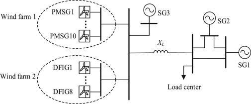
FIGURE 6. Configuration of example system.
Subsynchronous Oscillation Risk Evaluation Under Weak Grid Connection
The connection strength of the wind farm to the main AC grid can be evaluated using the SCR, which is defined as (IEEE Subsynchronous Resonance Task Force, 1977)
where Prated is the rated capacity of the wind farm. The strength of the connection of the wind farm to the AC grid decreases with an increase in the SCR value. If we take Prated = 1 (p.u.) and V0 = 1 (p.u.), then
When the SCR is less than or equal to 2, the wind farm is considered to be weakly connected to the AC grid. In this study case, XL is initially set to 0.5. Thus, the SCR is approximately 2, and the wind farm is weakly connected to the grid.
First, the risk of the SSO of the system under a weak grid connection was assessed. The oscillation mode of the system was calculated according to the improved complex torque coefficient method, and an unstable shaft oscillation mode was found for the third SG, λ1 = 0.46 ± 99.20j. Then, eigenvalue analysis was carried out based on the full-order model of the system, and the real value of this oscillation mode was obtained to be λ1’ = 0.33 ± 98.73j, which is very close to the calculation result obtained via the improved complex torque coefficient method. Thus, the effectiveness of the improved complex torque coefficient method was confirmed. Furthermore, the participation factor of this oscillation mode was calculated, and the result is shown in Figure 5A, which indicates that the unstable shaft oscillation mode is related to not only the third SG but also the PMSGs in wind farm 1. To more clearly analyze the influence of the PMSGs on the shaft system of the SG under a weak grid connection, the participation factors of each PMSG in wind farm one were expanded, as shown in Figure 5B, which indicates that all the PMSGs participate in the unstable shaft oscillation mode and that the state variables of a large participation factor of the oscillation mode are related to the DCVLs of the PMSGs.
In the next study cases, the influence of the GSC control parameters of the PMSG and the number of PMSGs in the wind farm on the SSO of the shaft system of the SG was investigated under different grid connection strengths.
Impact of GSC Control Parameters of Permanent-Magnet Synchronous Generators Under Different Grid Connection Strengths
According to the previously calculated participation factors (Section SSO Risk Evaluation under Weak Grid Connection), the dynamic interaction between the DCVL of the GSC of the PMSG in wind farm one and the shaft system of the third SG can cause the SSO in the example power system. We denote the proportional and integral coefficients of the PI controller of the DCVL of the PMSG as Kpdc and Kidc, respectively, and the corresponding oscillation mode of the wind farm as λ2. Then, the impact of the GSC control parameters of the PMSG under different grid connection strengths was studied by setting different values for XL, thereby giving different grid connection strengths to the system and helping us observe the influence of Kidc on the shaft oscillation mode. The Kidc value of each PMSG in wind farm one was gradually increased from 150 to 250. The variation in the root loci of the oscillation modes λ1 and λ2 with a change in Kidc is shown in Figure 7. In this figure, the black solid line corresponds to the case of XL = 0.5 and the SCR is approximately 2, which indicates a weak grid connection. The red solid line corresponds to the case of XL = 0.4 and the SCR is approximately 2.5, which indicates a relatively weak grid connection. The blue solid line corresponds to the case of XL = 0.3, and the SCR is approximately 3.33, which indicates a strong grid connection. The green hollow circle is the initial decoupling value of the SG shaft system. The curves of the corresponding shaft damping torque De according to the change in Kidc under different grid connection strengths are shown as black, red, and blue solid lines in Figure 8.
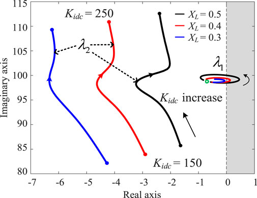
FIGURE 7. Root loci of λ1 and λ2 with change in Kidc under different grid connection strengths.
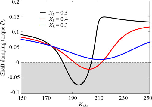
FIGURE 8. Curves of shaft damping torque De with change in Kidc under different grid connection strengths.
From Figures 7, 8, it can be seen that as Kidc gradually increases from 150 to 250, the interaction between the shaft of the third SG and the GSC DCVL of the PMSG gradually increases. The oscillation mode λ1 first moves toward the right half of the complex plane, and the system tends to be unstable. With a further increase in Kidc, the interaction between the shaft of the third SG and the GSC DCVL of the PMSG gradually weakens and λ1 returns to the left half of the plane again; i.e., the system returns to stability. Figures 9A–D show the participation factors under different Kidc values when XL = 0.5, which clearly reflects the process shown in Figure 8.
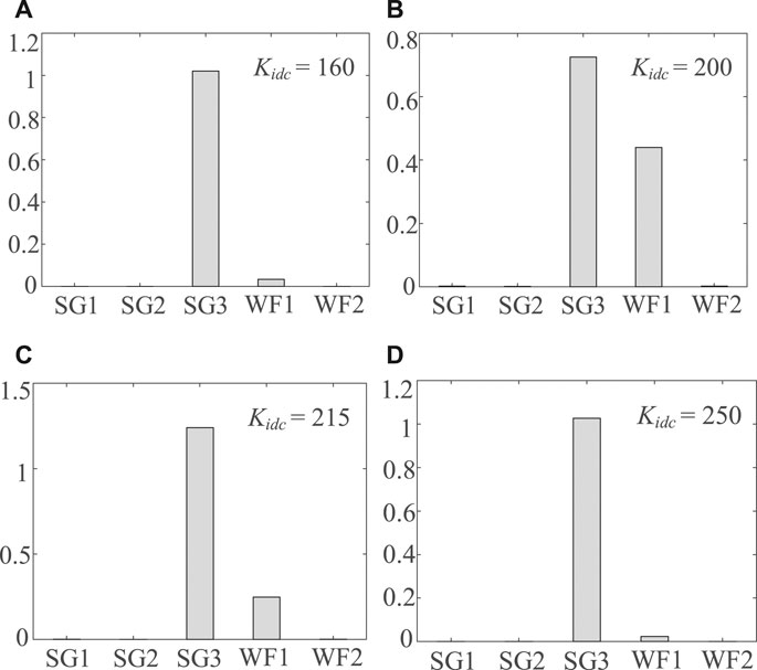
FIGURE 9. Participation factor of λ1 for different Kidc values (XL = 0.5): (A)Kidc = 160, (B)Kidc = 200, (C)Kidc = 215, and (D)Kidc = 250.
In addition, from the root locus of λ1 and the curve of the corresponding damping torque De under different Kidc values shown in Figures 7, 8, it can be seen that with a decrease in XL, i.e., with an increase in the connection strength, the damping of the shaft oscillation mode improves. When XL = 0.3, the system remains stable while Kidc increases from 150 to 250.
The simulation results presented in this section show that for the SSO caused by the dynamic interaction between the PMSG and the shaft of the SGs, the control parameters of the PMSG and the grid connection strength have a considerable impact on the system stability, and unreasonable parameter settings and a weak grid connection can lead to oscillation instability in the system.
To verify the correctness of the above analysis results, nonlinear simulation was performed when Kidc was set to 150 (corresponding to a weak dynamic interaction between wind farm one and the third SG) and 200 (corresponding to a strong dynamic interaction between wind farm one and the third SG) under three different grid connection strengths (Figure 10A–C). During the simulation, the input power of each PMSG in wind farm one was set to increase by 5% at 0.1 s to reflect a sudden increase in the wind speed and the sudden increase lasted for 0.01 s. The nonlinear simulation results were consistent with the results of the previous analysis.
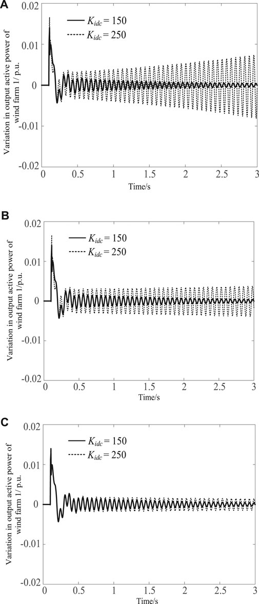
FIGURE 10. Nonlinear simulation results: (A)XL = 0.5, (B)XL = 0.4, and (C)XL = 0.3.
In addition, it is found through calculation that when XL = 0.354, In the process of Kidc increasing gradually, the root trajectory of the shaft oscillation mode is just tangent to the dividing line where the real part of the complex plane is zero. When Kidc = 208, the system is in a critical stable state, where Δλki is about 0.7. The nonlinear simulation results under this parameter environment are shown in Figure 11.
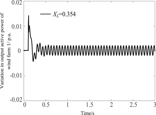
FIGURE 11. Nonlinear simulation results of critical stable state.
Impact of Number of PMSGs Under Different Grid Connection Strengths
Next, the influence of the number of PMSGs in the wind farm on the stability of the SG shaft system under different connection strengths was analyzed. The black, red, and blue solid lines in Figure 12 represent the root loci of the shaft oscillation mode of the third SG, λ1, with a change in the transmission line reactance XL when wind farm one contained 10, 15, and 20 PMSGs, respectively. The black, red, and blue solid lines in Figure 13 represent the curves of the corresponding shaft damping torque De as XL varied when wind farm one contained 10, 15, and 20 PMSGs, respectively. XL was set to increase from 0.2 to 0.5; i.e., the SCR decreased from 5 to 2, and the grid connection varied from strong to weak.
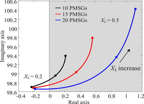
FIGURE 12. Root loci of
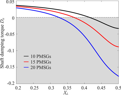
FIGURE 13. Curve of De with variation in XL under different number of PMSGs.
From Figures 12, 13, it can be seen that as the number of PMSGs in the wind farm increases, λ1 gradually moves to the right half of the complex plane and the risk of instability in the SG shaft system increases. In addition, as XL increases, the number of PMSGs affects the stability more clearly.
The nonlinear simulation results in Figure 14 confirm the correctness of the conclusions drawn from the previous analysis, and the disturbance provided to the example system during the simulation was the same as that in the previous analysis. From the nonlinear simulation results, it can be seen that when the wind farm contains different number of PMSGs, the system loses stability under a small disturbance when the grid connection is weak, whereas the system remains stable when the connection strength is strong. In addition, as the number of PMSGs increases, the risk of oscillation instability also increases.
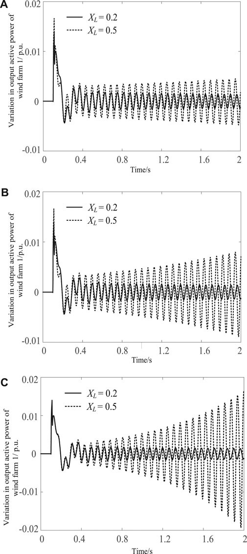
FIGURE 14. Nonlinear simulation results: (A) 10 PMSGs, (B) 15 PMSGs, and (C) 20 PMSGs.
Conclusion
This study investigated the influence of multiple PMSGs on the stability of the shaft system of an SG in an AC power system and revealed the mechanism governing the effect of the connection strength between the PMSG and AC power system on the stability of the SG shaft system based on an improved complex coefficient method. In addition, a method to determine the stability of the AC power system while considering the integration of PMSGs was developed. The main conclusions of this study can be summarized as follows:
1) When the length of the line connecting the PMSG to the AC power system increases, the same voltage change that occurs at the point of common coupling can cause a greater power response of the PMSG, which can increase the impact of the integration of the PMSG on the AC power system.
2) Based on the improved complex torque coefficient method, it is concluded that the electrical damping torque coefficient injected by the PMSG into the SG is proportional to the reactance of the connecting line between the PMSG and AC power system. When the PMSG is connected to the grid through a long-distance line, the electric damping torque coefficient injected by the PMSG also increases.
3) The PMSG provides a large damping torque coefficient to the SG shaft system under a weak grid connection. If the sensitivity of the oscillation mode to the torque coefficient is positive, the stability of the SG shaft system will reduce because of the weak grid connection. If the reduced damping is greater than the damping of the original oscillation mode, oscillation instability will occur.
Data Availability Statement
The original contributions presented in the study are included in the article/Supplementary Material, further inquiries can be directed to the corresponding author.
Author Contributions
The manuscript was written through contributions of all authors. All authors have read and agreed to the published version of the manuscript.
Conflict of Interest
The authors declare that the research was conducted in the absence of any commercial or financial relationships that could be construed as a potential conflict of interest.
Publisher’s Note
All claims expressed in this article are solely those of the authors and do not necessarily represent those of their affiliated organizations, or those of the publisher, the editors and the reviewers. Any product that may be evaluated in this article, or claim that may be made by its manufacturer, is not guaranteed or endorsed by the publisher.
Supplementary Material
The Supplementary Material for this article can be found online at: https://www.frontiersin.org/articles/10.3389/fenrg.2021.742304/full#supplementary-material
References
Alawasa, K. M., Mohamed, Y. A.-R. I., and Xu, W. (2013). Modeling, Analysis, and Suppression of the Impact of Full-Scale Wind-Power Converters on Subsynchronous Damping. IEEE Syst. J. 7, 700–712. doi:10.1109/JSYST.2012.2226615
Canay, I. M. (1982). A Novel Approach to the Torsional Interaction and Electrical Damping of the Synchronous Machine Part I: Theory. IEEE Trans. Power Appar. Syst. PAS-101, 3630–3638. doi:10.1109/TPAS.1982.317048
Dong, D., Wen, B., Boroyevich, D., Mattavelli, P., and Xue, Y. (2015). Analysis of Phase-Locked Loop Low-Frequency Stability in Three-phase Grid-Connected Power Converters Considering Impedance Interactions. IEEE Trans. Ind. Electron. 62, 310–321. doi:10.1109/TIE.2014.2334665
Du, W., Bi, J., Cao, J., and Wang, H. F. (2016). A Method to Examine the Impact of Grid Connection of the DFIGs on Power System Electromechanical Oscillation Modes. IEEE Trans. Power Syst. 31, 3775–3784. doi:10.1109/TPWRS.2015.2494082
Du, W., Chen, X., and Wang, H. F. (2017a). Power System Electromechanical Oscillation Modes as Affected by Dynamic Interactions from Grid-Connected PMSGs for Wind Power Generation. IEEE Trans. Sustain. Energ. 8, 1301–1312. doi:10.1109/TSTE.2017.2677094
Du, W., Fu, Q., and Wang, H. (2017B). Subsynchronous oscillations caused by open-loop modal coupling between VSC-based HVDC line and power system. IEEE Trans. Power Syst 33, 3664–3677. doi:10.1109/TPWRS.2017.2771764
Du, W., Fu, Q., and Wang, H. (2020a). Damping Torque Analysis of DC Voltage Stability of an MTDC Network for the Wind Power Delivery. IEEE Trans. Power Deliv. 35, 324–338. doi:10.1109/TPWRD.2019.2933641
Du, W., Fu, Q., and Wang, H. (2018b). Subsynchronous Oscillations Caused by Open-Loop Modal Coupling between VSC-Based HVDC Line and Power System. IEEE Trans. Power Syst. 33, 3664–3677. doi:10.1109/TPWRS.2017.2771764
Du, W., Wang, Y., Wang, H., Xiao, X., Wang, X., and Xie, X. (2020b). Analytical Examination on the Amplifying Effect of Weak Grid Connection for the DFIGs to Induce Torsional Sub-synchronous Oscillations. IEEE Trans. Power Deliv. 35, 1928–1938. doi:10.1109/TPWRD.2019.2957005
Du, W., Wang, Y., Wang, Y., Wang, H., and Xiao, X. (2021). Analytical Examination of Oscillatory Stability of a Grid-Connected PMSG Wind Farm Based on the Block Diagram Model. IEEE Trans. Power Syst., 1. doi:10.1109/TPWRS.2021.3077121
Fan, L., Kavasseri, R., Miao, Z. L., and Zhu, C. (2010). Modeling of DFIG-Based Wind Farms for SSR Analysis. IEEE Trans. Power Deliv. 25, 2073–2082. doi:10.1109/TPWRD.2010.2050912
Fu, Q., Du, W., Wang, H. F., and Ren, B. (2021a). Analysis of Small-Signal Power Oscillations in MTDC Power Transmission System. IEEE Trans. Power Syst. 36, 3248–3259. doi:10.1109/TPWRS.2020.3043041
Fu, Q., Du, W., Wang, H., Ren, B., and Xiao, X. (2021b). Small-signal Stability Analysis of a VSC-MTDC System for Investigating DC Voltage Oscillation. IEEE Trans. Power Syst., 1. doi:10.1109/TPWRS.2021.3072399
Gao, B., Li, R., Yang, D., and Song, R. (2015). Damping Characteristics and Countermeasure of DFIG Sub-synchronous Oscillation. Electr. Power Autom. Equip. 35, 11–20. doi:10.16081/j.issn.1006-6047.2015.12.002
Hansen, A. D., and Michalke, G. (2009). Multi-pole Permanent Magnet Synchronous Generator Wind Turbines' Grid Support Capability in Uninterrupted Operation during Grid Faults. IET Renew. Power Gener. 3 (3), 333–348. doi:10.1049/iet-rpg.2008.0055
IEEE Subsynchronous Resonance Task Force (1977). First Benchmark Model for Computer Simulation of Subsynchronous Resonance. IEEE Trans. Power Appar. Syst. 96, 1565–1572. doi:10.1109/T-PAS.1977.32485
Jiang, Z., Cheng, S., Fu, Y., and Liao, X. (2000). Analysis of Subsynchronous Resonance of Power System with TCSC. Proc. CSEE 20, 47–52. doi:10.13334/j.0258-8013.pcsee.2000.06.012
Liu, H., Xie, X., He, J., Xu, T., Yu, Z., Wang, C., et al. (2017). Subsynchronous Interaction between Direct-Drive PMSG Based Wind Farms and Weak AC Networks. IEEE Trans. Power Syst. 32, 4708–4720. doi:10.1109/TPWRS.2017.2682197
Nasiri, M., Milimonfared, J., and Fathi, S. H. (2015). A Review of Low-Voltage Ride-Through Enhancement Methods for Permanent Magnet Synchronous Generator Based Wind Turbines. Renew. Sust. Energ. Rev. 47, 399–415. doi:10.1016/j.rser.2015.03.079
Nasiri, M., and Mohammadi, R. (2017). Peak Current Limitation for Grid Side Inverter by Limited Active Power in PMSG-Based Wind Turbines during Different Grid Faults. IEEE Trans. Sustain. Energ. 8 (1), 3–12. doi:10.1109/TSTE.2016.2578042
Ni, Y., Chen, S., and Zhang, B. (2002). Theory and Analysis of Power System Dynamics. Beijing: Tsinghua Press.
Piyasinghe, L., Miao, Z., Khazaei, J., and Fan, L. (2015). Impedance Model-Based SSR Analysis for TCSC Compensated Type-3 Wind Energy Delivery Systems. IEEE Trans. Sustain. Energ. 6, 179–187. doi:10.1109/TSTE.2014.2362499
Wang, Y., Du, W., and Wang, H. (2021). Analysis of Subsynchronous Oscillation in Multi-Machine Power System Caused by the Integration of Multiple Wind Farms Based on Improved Complex Torque Coefficient Method. Proc. CSEE 41, 2383–2395. doi:10.13334/j.0258-8013.pcsee.191653
Xie, X., Wang, L., He, J., Liu, H., Wang, C., and Zhan, Y. (2017). Analysis of Subsynchronous Resonance/oscillation Types in Power Systems. Power Syst. Technol. 41, 1043–1049. doi:10.13335/j.1000-3673.pst.2016.2641
Xiong, L., Liu, X., Liu, Y., and Zhuo, F. (2020). Modeling and Stability Issues of Voltage-Source Converter Dominated Power Systems: a Review. Csee Jpes, 1–18. doi:10.17775/CSEEJPES.2020.03590
Xiong, L., and Zhuo, F. (2013). “A Novel DC Voltage Balancing Method for Cascaded STATCOM,” in 2013 Twenty-Eighth Annual IEEE Applied Power Electronics Conference and Exposition (APEC), Long Beach, 17-21 March 2013 (IEEE), 924–929. doi:10.1109/APEC.2013.6520321
Xu, Z. (2000). The Complex Torque Coefficient Approach’s Applicability Analysis and its Realization by Time Domain Simulation. Proc. CSEE 20, 2–5. doi:10.13334/j.0258-8013.pcsee.2000.06.001
Zhang, K., Zhou, B., Or, S. W., Li, C., Chung, C. Y., and Voropai, N. I. (2021). Optimal Coordinated Control of Multi-Renewable-To-Hydrogen Production System for Hydrogen Fueling Stations. IEEE Trans. Ind. Applicat., 1. doi:10.1109/TIA.2021.3093841
Zhang, M., Xiao, S., Tian, T., Zhang, H. H., Bi, T. S., and Liang, F. B. (2018). Analysis of SSO Influencing Factors and Parameter Adjustment for Grid-Connected Full-Converter Wind Farm Based on Impedance Sensitivity. Power Syst. Technol. 42, 2768–2777. doi:10.13335/j.1000-3673.pst.2018.0687
Keywords: permanent-magnet wind-power generator, complex torque coefficient method, shaft system, synchronous generator, small-signal stability
Citation: Zhang T and Wang H (2021) Method to Evaluate the Impact of Integration of PMSG on Stability of Synchronous Generator Shaft Under Weak Grid Connection. Front. Energy Res. 9:742304. doi: 10.3389/fenrg.2021.742304
Received: 16 July 2021; Accepted: 10 August 2021;
Published: 23 August 2021.
Edited by:
Liansong Xiong, Nanjing Institute of Technology (NJIT), ChinaReviewed by:
Yang Liu, Lanzhou Jiaotong University, ChinaMojtaba Nasiri, Trinity College Dublin, Ireland
Copyright © 2021 Zhang and Wang. This is an open-access article distributed under the terms of the Creative Commons Attribution License (CC BY). The use, distribution or reproduction in other forums is permitted, provided the original author(s) and the copyright owner(s) are credited and that the original publication in this journal is cited, in accordance with accepted academic practice. No use, distribution or reproduction is permitted which does not comply with these terms.
*Correspondence: Haifeng Wang, aGZ3YW5nNjBAcXEuY29t