 Aijing Zhang
 Shengjuan Jiang
95% of researchers rate our articles as excellent or good
Learn more about the work of our research integrity team to safeguard the quality of each article we publish.
Find out more
ORIGINAL RESEARCH article
Front. Energy Res. , 17 August 2021
Sec. Fuel Cells, Electrolyzers and Membrane Reactors
Volume 9 - 2021 | https://doi.org/10.3389/fenrg.2021.741806
Hollow mesoporous silica (HMS) has attracted significant attention for fuel cell applications. The mesopores in the shell can accelerate proton transport and the void in the center of the particle is advantageous for proton storage. However, the conventional methods for HMS fabrication are complicated, which is not conducive to scaling up the fabrication of HMS. In this work, a new, simple strategy to synthesize HMS has been developed via OH− ion exchange-induced etching of mesoporous silica (mSiO2). The mSiO2 immersed in an alkaline Na2CO3 solution led to an exchange of the Br− ions in the surfactant with the OH− ions in the solution, resulting in a high concentration of OH− ions in the mesoporous channels of mSiO2 close to the core, and a low concentration of OH− ions close to the surface. This demonstrated that the etching of the core of mSiO2 was induced, which extended from the core to the surface of the nanoparticles. Furthermore, the success of the ion exchange-induced etching process was demonstrated by the gradient distribution of the Na+ ion in mesoporous silica microspheres through microscopy. In addition, the proton conductivity of the phosphoric acid-impregnated HMS membrane at 180°C under anhydrous conditions was found to be 0.025 S.cm−1. These results demonstrate the simplicity of the ion exchange-induced etching strategy for the fabrication of HMS microspheres and its promising application in high temperature proton exchange membrane fuel cells.
Proton exchange membrane fuel cells (PEMFCs) have attracted significant attention due to their outstanding energy efficiency and high power density (Sun et al., 2019a). According to the operating temperature, PEMFCs are divided into low-temperature PEMFCs (LT-PEMFC) working below 80°C and high-temperature PEMFCs (HT-PEMFC) that work over 150°C (Søndergaard et al., 2018). In comparison with LT-PEMFC, the HT-PEMFC has advantages including improved resistance towards CO poisoning, fast electrode reaction kinetics and flexible fuel supply (Li et al., 2009). HT-PEMFCs are promising in a wide range of applications, including combined heat and power, uninterrupted power supply and cars based on fuel cells. One of the core materials of HT-PEMFCs is the high-temperature proton exchange membrane (HT-PEM) that requires high proton conductivity under high operating temperature and anhydrous conditions (Nambi Krishnan et al., 2019). The proton conductivity of the HT-PEM tends to increase with the introduction of highly ordered meso-channels. Jiang et al. (Aili et al., 2016; Zhang et al., 2017) significantly enhanced the proton conductivity of a phosphoric acid-doped polybenzimidazole membrane at 200°C by introducing mesoporous silica into the polymer membrane.
Compared to mesoporous silica, hollow mesoporous silica (HMS) has both meso-channels that accelerate proton transport and hollow voids for electrolyte storage, and has received significant attention in HT-PEMs (Zhang and Jiang, 2016; Zhang et al., 2019; Zhao et al., 2020a). Jiang et al. (Zhang et al., 2018) increased the proton conductivity of the pristine Nafion® membrane at 140°C and low relative humidity (0.55%) by two orders of magnitude by adding a small amount of ionic liquid-impregnated HMS to the membrane. In addition, the introduction of amine-functionalized mesoporous silica into a phosphoric acid-doped polyethersulfone-polyvinylpyrrolidone polymer also increased the proton conductivity of the membrane at 180°C and anhydrous conditions by 24.6% (Zhang et al., 2016). However, the synthesis of HMS usually requires the hard template method, which not only leads to a complicated synthesis process, it is not also conducive to scaling up the production of HMS (Soltys et al., 2018).
Several new strategies have recently been developed for the fabrication of HMS (Qiu et al., 2019). Teng et al. (Teng et al., 2013) transformed mesoporous silica microspheres obtained from the Stöber method into HMS via a selective etching process, which is based on the principle that the condensation degree of the outer layer is higher in comparison to the core. Furthermore, the combination of mesoporous silica with multiple interfaces and a one-step hydrothermal treatment leads to the formation of multi-shell hollow mesoporous silica microspheres (Teng et al., 2015). Although the transformation procedure does not require any sacrificial template or surface protection agent, these methods either cause disorder of the mesoporous channels in the shell or require harsh reaction conditions (hydrothermal reaction, etc.) (Li et al., 2011). While only a few theories have been established for the formation mechanism of HMS, which includes surface protection etching, Ostwald ripening and cationic surfactant-assisted selective etching (Fang et al., 2011), the formation mechanism of HMS is rarely studied and verified through microscopy. Consequently, it is still a significant challenge to develop a facile and controllable method for the synthesis of HMS and verify the formation mechanism.
Herein, we demonstrated a novel solid-to-hollow transformation approach for the fabrication of HMS via an ion exchange-induced selective etching method. The formation mechanism of the HMS was verified by scanning transmission electron microscopy (STEM) combined with energy dispersive X-ray spectroscopy (EDS). In addition, the HMS was impregnated by phosphoric acid to fabricate an inorganic composite HT-PEM (PA/HMS). The proton conductivity of the as-synthesized composite membrane under high temperature conditions was investigated as a proof-to-concept for fuel cell applications. The outstanding proton conductivity of the PA/HMS composite membrane achieved in this study is promising for HT-PEMFCs.
Tetraethyl orthosilicate (TEOS), cetyltrimethylammonium bromide (CTAB), ethanol (EtOH), aqueous HCl (32 wt%), phosphoric acid (85 wt% H3PO4), aqueous ammonia (28 wt%, NH3·H2O) and sodium carbonate were purchased from Sinopharm Chemical Reagent Co., Ltd. Polytetrafluoroethylene (PTFE) emulsion (15 wt%) was bought from Dupont. All chemicals were used as received without further purification. The carbon paper with gas diffusion layer was purchased from Shanghai Hesen Electric Co., Ltd.
CTAB was added to a solution containing deionized water and EtOH. The mixture was stirred at room temperature until the CTAB was completely dissolved. Then, NH3·H2O (28 wt%) and TEOS were added to the solution one after another. The molar ratio of H2O:EtOH:NH3·H2O:CTAB:TEOS was 2,756:518:3.9:0.4:1.0. After stirring for 6 h at room temperature, the transparent solution changed to a milky white suspension. Then, the suspension was centrifuged at 10,000 rpm for 10 min to obtain a white solid, which was labeled mSiO2. The white mSiO2 powder was re-dispersed in 50 ml of deionized water to obtain a suspension which was then stirred in a 0.2 M Na2CO3 solution at 60°C for 10 h. After that, the suspension was centrifuged at 10,000 rpm for 10 min to obtain a white solid. The white solid was heated in a vacuum oven at 80°C for 2 h and was then sintered in a furnace at 550°C (5°C.min−1) in air for 2 h. The sintered sample was collected and labeled HMS. To extract the CTAB from mSiO2, the mSiO2 sample was refluxed in a solution of 100 ml EtOH and 3.0 ml HCl (32 wt%) at 80°C for 3 h. Then, the suspension was centrifuged at 10,000 rpm for 10 min. The obtained white solid was dried in a vacuum drying oven at 80°C for 2 h, and labeled mSiO2-r.
HMS was mixed with the PTFE emulsion and the mixture was heated in a vacuum oven at 80°C for 6 h. Then the mixture was placed in a tablet press machine and hot-pressed at 180°C and 100 MPa for 30 min to obtain the HMS membrane. After that, the HMS membrane was doped with phosphoric acid by a vacuum impregnation method (Lu et al., 2010). More specifically, the HMS membrane was placed in a glass desiccator that was connected to a mechanical pump and phosphoric acid solution through a three-way glass valve. The mechanical pump was run till the pressure of the glass desiccator was lower than 0.01 MPa, and the valve connecting the glass desiccator was closed. Then, the valve connecting the phosphoric acid solution was slowly opened so that the phosphoric acid solution was sucked into the HMS membrane due to the pressure difference between the desiccator and the atmosphere.
The microstructure of the inorganic powders was examined by an FEI Titan G2 high-angle annular dark-field scanning transmission electron microscope (HAADF-STEM), with an accelerating voltage of 200 kV. The small angle X-ray scattering (SAXS) analysis on the solid powder was conducted at the 1W2A line station of the Beijing synchrotron radiation source, where the X-ray wavelength was 0.154 nm, and the detector was a Mar165 CCD detector (2048 × 2048 pixels, with a pixel size of 80 mm). The Brunauer-Emmett-Teller (BET) surface area of the samples was measured by the nitrogen adsorption isotherm (Micromeritics ASAP 2020) and before the measurement, the samples were degassed at 100°C for 9 h. Zeiss Neon 40 EsB scanning electron microscope (SEM) was used to study the morphology of HMS and the cross-sectional morphology of the inorganic membrane. The accelerating voltage of the SEM was 5 kV. The thermogravimetric curve of the sample was obtained by the Q500 TGA analyzer of American TA Instruments under nitrogen atmosphere and a flow rate of 50 ml.min−1.
The PA/HMS membrane was sandwiched by two pieces of carbon paper, with an area of 4 cm2. Then, it was placed in a fuel cell hardware with a torque value of 2 N.m. The proton conductivity of the membrane was measured by a potentiostat (IVIUM, Netherland) with a frequency range of 100 kHz to 100 Hz and an amplitude of 10 mV under different temperatures.
The fabrication of the PA/HMS membrane is shown in Figure 1. First, mSiO2 particles with a mesoporous structure were synthesized by a modified Stöber method. Then, the mSiO2 spheres were transformed into HMS spheres by an ion exchange-induced selective etching method. PA was doped into HMS by vacuum impregnation method to achieve the PA/HMS composite.
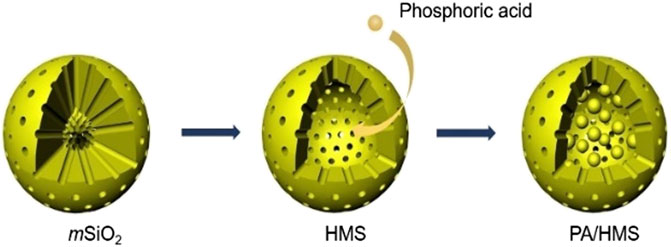
FIGURE 1. Scheme for the fabrication of PA/HMS composite.
The obtained mSiO2 particles have a regular spherical shape with a uniform size distribution, as shown in Figure 2A. The average size of the particles is 281 ± 54 nm. In addition, the mSiO2 particles show a solid structure with worm-like mesopores oriented radially outwards from the center of the particle (Figure 2B). However, after immersing the mSiO2 in a 0.2 M Na2CO3 solution at 60°C for 10 h, the solid core of the particles was etched to a hollow structure (Figure 2C), whereas the edge of the particles remained intact with a worm-like mesoporous structure. In addition, the average diameter of the HMS particles was 276 ± 32 nm, which is close to the average size of the solid mSiO2. The results demonstrate that it is only the core of the mSiO2 that is etched instead of the edge of the particles. Furthermore, the HAADF-STEM images in Figure 2D show that various HMS particles have different thicknesses, indicating the extension of the etching process from the core to the outer layer of mSiO2 (Hao et al., 2015). Moreover, the homogeneous distribution of O (Figure 2E) and Si (Figure 2F), in the whole hollow microsphere shell, confirms that the HMS was composed of SiO2.
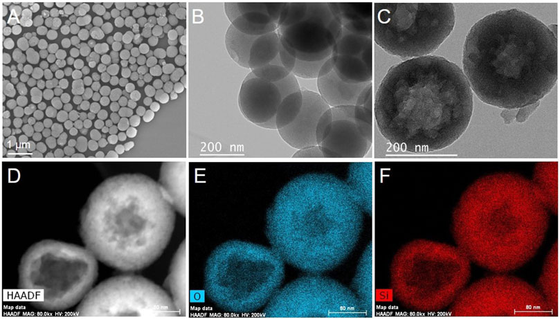
FIGURE 2. (A) SEM and (B) TEM images of mSiO2, (C) TEM and (D) HAADF-STEM images of HMS and (E) O and (F) Si element mapping of HMS.
Figure 3A shows the SAXS curves of mSiO2 and HMS particles. There is a broad peak in the SAXS curve of mSiO2 centered at 0.133 Å, which corresponds to a d-spacing of 4.7 nm (Zhang et al., 2014). When mSiO2 is transformed into HMS, a broad peak is also observed centered at 0.139 Å in the SAXS curves of HMS, corresponding to a d-spacing of 4.5 nm. The similarity in the d-spacing values of mSiO2 and HMS indicates that the mesoporous structure of HMS is the same as that of mSiO2. In addition, the specific surface areas and pore sizes of mSiO2 and HMS were characterized by the N2 isotherm curves, as shown in Figure 3B. The N2 isotherm curves of mSiO2 and HMS are both type IV curves, confirming the mesoporous structure of both mSiO2 and HMS (Hao et al., 2015). The BET surface area of mSiO2 was found to be 1,423 cm2g−1. After the etching process, the BET surface area of HMS reduced to 896 cm2g−1, which is 37% lower than that of the mSiO2. This is due to the dissolution of the center of mSiO2 (Li et al., 2015). In addition, the pore sizes of HMS and mSiO2 are 3.2 and 3.4 nm, respectively, indicating that the mesoporous structure of mSiO2 remained the same before and after etching. The results verify that only the inside of the solid mSiO2 was dissolved during the formation of HMS via the solid-to-hollow structure transformation.
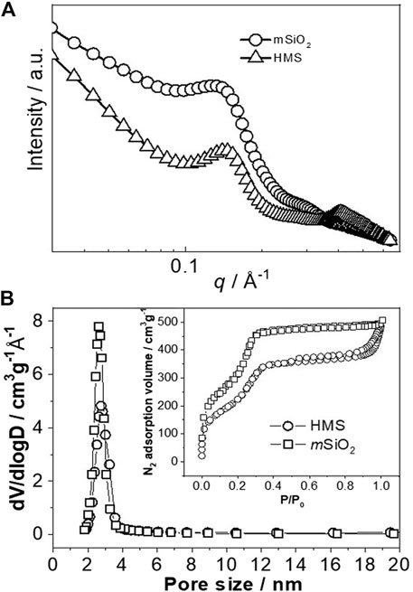
FIGURE 3. (A) SAXS and (B) N2 adsorption and desorption curves of mSiO2 and HMS.
To observe the transformation process of mSiO2 to HMS, the morphology of the mSiO2 particles that were stirred in a 0.2 M Na2CO3 solution at 60°C, for different times, was observed, as shown in Figure 4. The mSiO2 particles show a uniform solid structure with no void in their center. When it was reacted in a 0.2 M Na2CO3 solution at 60°C for 2 h, a void of size of 40 ± 16 nm was formed in the center of the mSiO2 particle (Figure 4B). When the reaction time was extended to 15 h, the size of the void increased to 110 ± 30 nm (Figure 4C). In addition, the SAXS characterization was conducted on the mSiO2 samples with different etching times (Figure 4D). In the etching time range of 0–20 h, a broad peak was observed in the SAXS curve of all the samples located at 0.135 Å. Similar q values for each sample indicate that the size of the mesoporous structure of mSiO2 remained the same during the entire etching period. Consequently, on increasing the reaction time, the mSiO2 was gradually etched from the inside to the outside, and finally, a hollow mesoporous silica microsphere, with a certain shell thickness, was formed.
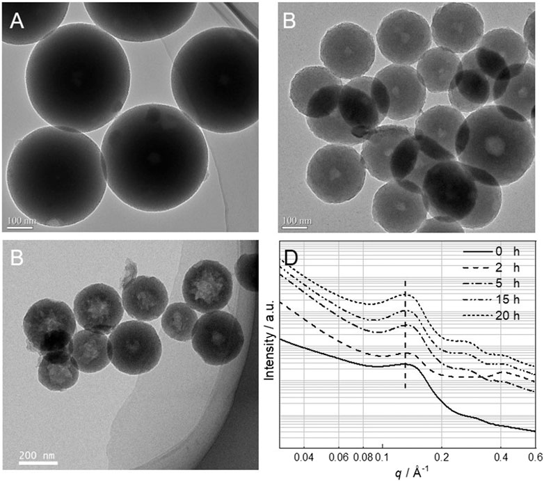
FIGURE 4. TEM images of mSiO2 under different etching times (A) 0 h, (B) 2 h, (C) 15 h, (D) SAXS images of mSiO2 under different etching times.
As shown in Figure 5A, significant weight loss (33.1 wt%) occurred in mSiO2 starting from 180°C, which is assigned to the decomposition of CTAB. When mSiO2 was refluxed in an ethanol solution containing HCl for 3 h, the weight loss of the particles at temperatures above 180°C was only 5.2 wt%, indicating that CTAB was almost completely removed in mSiO2-r. In addition, the spherical and mesoporous structure of mSiO2-r is clearly observed (Figure 5B), indicating that the removal of CTAB in mSiO2 did not affect the mesoporous structure of the particles. Generally, the mSiO2 is formed by self-assembly and condensation of Si-OH on the surface of CTAB micelles which act as a soft template (Li et al., 2017; Sun et al., 2019b). In addition, solid SiO2 spheres can also be transformed into HMS with the assistance of CTAB through the interaction and self-assembly of Si-OH that derives from the dissolution of solid SiO2 and CTAB (Ghasemi et al., 2017; Su et al., 2019). Thereby, CTAB tends to play a critical role in the transformation of mSiO2 to HMS in this case. To verify this inference, the mSiO2-r was etched in the 0.2 M Na2CO3 solution at 60°C for 10 h. The spherical structure of mSiO2-r transformed into an amorphous lamellar structure with an absence of the mesoporous structure (Figure 5C), and HMS was not obtained. Therefore, CTAB plays a critical role in the transformation of mSiO2 particles to HMS in this case.
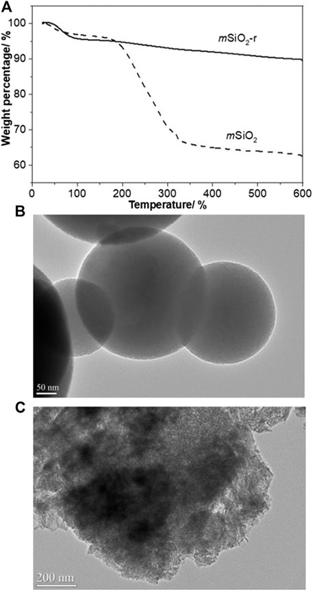
FIGURE 5. (A) TGA curves of mSiO2 and mSiO2-r, (B) TEM image of mSiO2-r, (C) TEM image of mSiO2-r after being etched at 0.2 M Na2CO3 at 60°C for 10 h.
Figure 6 shows the HAADF-STEM and elemental mapping of mSiO2 after immersion in the 0.2 M Na2CO3 solution at room temperature for 10 min. The mSiO2 particle shows a solid structure, and the Si (Figure 6B) and O (Figure 6C) are shown to be evenly distributed in the particle. In addition, the uniform distributions of C (Figure 6D) and N (Figure 6E) in the entire mSiO2 particle confirm the homogeneous distribution of CTAB in the mesoporous channels of mSiO2. On the other hand, the intensity of the peak of Na in the center of the mSiO2 particle was higher than that at the edge of the particle (Figure 6F). As Na+ ions are paired with OH− ions, the EDS result implies that the OH− ion concentration in the center of the mSiO2 particle is higher than that of the OH− ion at the edge of the particle. The OH− ions tend to attack the Si-O-Si bond in SiO2 and lead to the dissociation of Si-O-Si to Si-OH, resulting in the dissolution and etching of SiO2(Khoeini et al., 2019). Therefore, an ion exchange-induced selective etching mechanism is proposed for the solid-to-hollow transformation of mSiO2 to HMS. The mSiO2 derived from the modified Stöber method shows uniform distribution of CTAB in the worm-like mesopores of mSiO2 that are oriented from the center to the edge of the particle. When mSiO2 was placed in a weakly alkaline Na2CO3 solution, Br− ions in CTAB and OH− ions in the solution were exchanged, leading to the accumulation of OH− ions in the mesopores of mSiO2. Thereby, the concentration of OH− in the center of the particle was higher than the concentration of OH− ions in the solution. In addition, the OH− ions in the mesoporous channels on the edge of mSiO2 could easily exchange with the OH− ion in the solution under a dynamic equilibrium, leading to dilution of the OH− ions in the mesoporous channels close to the surface of the mSiO2 particle. In other words, the OH− concentration in the mesoporous channels of the mSiO2 particle gradually decreased from the center to the edge of the particle. Thereby, the center of the mSiO2 was dissolved by the high concentration of the OH− ion, leading to the formation of HMS. The void became larger in size along with the concentration gradient of OH− ion.
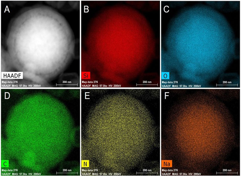
FIGURE 6. (A) HAADF-STEM image and element mapping of mSiO2: (B) Si element, (C) O element, (D) C element, (E) N element and (F) Na element.
The HMS is employed as the HT-PEM for HT-PEMFC. The HMS particles were hot-pressed into the inorganic membrane of diameter and thickness of 38 and 0.51 mm, respectively, as shown in Figure 7A. Then, the HMS membrane was doped with phosphoric acid to obtain a dense PA/HMS inorganic HT-PEM (Figure 7B). However, some pinholes in the PA/HMS membrane were found due to the existence of certain pores among the HMS particles, which may lead to higher gas permeability than that of pure polymer electrolyte membranes (Zhao et al., 2020b). In addition, the isothermal curve of PA/HMS in N2 still shows a type IV curve, indicating the existence of mesoporous structure in PA/HMS. On the other hand, the BET specific surface area of PA/HMS substantially decreased to 29 m2g−1 which is 98.0% lower than that of the pristine HMS particle. The drastically reduced BET surface area of HMS after PA doping demonstrates that a large number of phosphoric acid molecules entered the mesopores of HMS (Zeng et al., 2013). In addition, compared with the HMS that shows slight weight loss in the temperature range from 100–800°C, PA/HMS exhibited a significant weight loss (34.8 wt%) at temperatures above 100°C, with two peaks centered at 123°C and 205°C. The weight loss at 123°C is likely attributed to the volatilization of water molecules in the phosphoric acid solution, while the weight loss at 205°C is due to the dehydration of phosphoric acid molecules (Hoffmann et al., 2012). The abovementioned results indicate that a large number of phosphoric acid molecules have been successfully incorporated into HMS, which is beneficial to the proton conduction of the PA/HMS membrane.
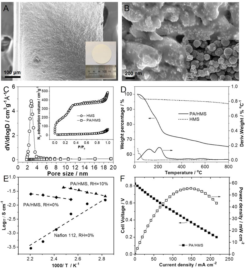
FIGURE 7. SEM image of (A) the HMS membrane, the inset is an optical photograph of HMS membrane and (B) the PA/HMS membrane, the inset is the SEM image of the surface of pristine HMS membrane. (C) N2 isotherm curves and (D) TGA curves of HMS and PA/HMS. (E) Proton conductivity of PA/HMS membrane under different temperature and humidity conditions. The Nafion®112 membrane is employed as reference. (F) Fuel cell polarization curves of PA/HMS at 160°C and 0% RH.
The proton conductivity of the PA/HMS membrane is shown in Figure 7E. Typically, at 0% relative humidity (RH), the proton conductivity of a Nafion®112 membrane tends to decrease from 1.5 × 10⁻² S.cm−1 at 80°C to 2.9 × 10⁻⁴ S.cm−1 at 180°C. This is due to the evaporation of free water from the membrane as the temperature rises (Zhang et al., 2014). Compared with the Nafion®112 membrane, the anhydrous proton conductivity of PA/HMS increased from 1.6 × 10⁻² S.cm−1 at 120°C to 2.5 × 10⁻² S.cm−1 at 180°C. This is likely due the fast proton conduction between H2PO4− and HPO42− through the Grotthuss mechanism (Asensio et al., 2010). Furthermore, when the RH increased to 10%, the proton conductivity of PA/HMS at 120°C increased to 4.0 × 10⁻² S.cm−1, which is 1.5 times higher than that of the membrane under 0% RH. In addition, the cell performance of the HT-PEMFC based on the PA/HMS membrane was measured at 160°C and 0% RH, as shown in Figure 7F. The open circuit voltage of the fuel cell under H2/O2 atmosphere is only 0.83 V, which is likely due to the gas permeation through the pinholes in the PA/HMS. However, the maximum output power of the fuel cell under 160°C reached 55.6 mW.cm−2. Therefore, this successful result demonstrates the feasibility of the PA/HMS inorganic membranes in HT-PEMFCs.
Hollow mesoporous silica particles were synthesized by etching mSiO2 microspheres in a weakly alkaline solution via an ion exchange-induced selective etching strategy. It was found that the mesoporous silica microspheres were etched from the center, and the volume of the void increased with the extension of the etching time. For the mSiO2 microspheres with CTAB in the mesopores, the Br− ions in CTAB were exchanged, with OH− ions in the alkaline solution, so that the OH− concentration in mSiO2 was higher than the concentration of OH− ions in the solution. As a result, the inside of the mSiO2 microspheres was etched first to form HMS. In addition, when HMS was impregnated by phosphoric acid via the vacuum impregnation method, the proton conductivity of PA/HMS at 160°C and 0% RH reached 2.5 × 10⁻² S.cm−1, and the peak power density of the HT-PEMFCs based on the PA/HMS membrane reached 55.6 mW.cm−2 under the same conditions. Therefore, the PA/HMS inorganic membrane is a promising candidate for applications in HT-PEMFCs.
The original contributions presented in the study are included in the article, further inquiries can be directed to the corresponding author.
Experiments and concepts were designed by SJ. AZ and SJ performed the methodology and investigation. Data collection and analysis was conducted by AZ and SJ. XS and JW obtained resources. Data interpretation and manuscript review/edit were conducted by all authors:AZ, SJ, XS, JW, MZ and MC.
This work has received financial support from the Beijing Municipal Science and Technology Project (Z191100004719006).
All authors are employed by State Power Investment Corporation Hydrogen Energy Company, Ltd. Co., Beijing.
All claims expressed in this article are solely those of the authors and do not necessarily represent those of their affiliated organizations, or those of the publisher, the editors and the reviewers. Any product that may be evaluated in this article, or claim that may be made by its manufacturer, is not guaranteed or endorsed by the publisher.
Aili, D., Zhang, J., Dalsgaard Jakobsen, M. T., Zhu, H., Yang, T., Liu, J., et al. (2016). Exceptional Durability Enhancement of PA/PBI Based Polymer Electrolyte Membrane Fuel Cells for High Temperature Operation at 200°C. J. Mater. Chem. A. 4, 4019–4024. doi:10.1039/c6ta01562j
Asensio, J. A., Sánchez, E. M., and Gómez-Romero, P. (2010). Proton-Conducting Membranes Based on Benzimidazole Polymers for High-Temperature PEM Fuel Cells. A Chemical Quest. Chem. Soc. Rev. 39, 3210–3239. doi:10.1039/b922650h
Fang, X., Chen, C., Liu, Z., Liu, P., and Zheng, N. (2011). A Cationic Surfactant Assisted Selective Etching Strategy to Hollow Mesoporous Silica Spheres. Nanoscale 3, 1632–1639. doi:10.1039/c0nr00893a
Ghasemi, S., Farsangi, Z. J., Beitollahi, A., Mirkazemi, M., Rezayat, S. M., and Sarkar, S. (2017). Synthesis of Hollow Mesoporous Silica (HMS) Nanoparticles as a Candidate for Sulfasalazine Drug Loading. Ceramics Int. 43, 11225–11232. doi:10.1016/j.ceramint.2017.05.172
Hao, N., Jayawardana, K. W., Chen, X., and Yan, M. (2015). One-Step Synthesis of Amine-Functionalized Hollow Mesoporous Silica Nanoparticles as Efficient Antibacterial and Anticancer Materials. ACS Appl. Mater. Inter. 7, 1040–1045. doi:10.1021/am508219g
Hoffmann, T., Friedel, P., Harnisch, C., Häußler, L., and Pospiech, D. (2012). Investigation of Thermal Decomposition of Phosphonic Acids. J. Anal. Appl. Pyrolysis 96, 43–53. doi:10.1016/j.jaap.2012.03.001
Khoeini, M., Najafi, A., Rastegar, H., and Amani, M. (2019). Improvement of Hollow Mesoporous Silica Nanoparticles Synthesis by Hard-Templating Method via CTAB Surfactant. Ceramics Int. 45, 12700–12707. doi:10.1016/j.ceramint.2019.03.125
Li, Q., Jensen, J. O., Savinell, R. F., and Bjerrum, N. J. (2009). High Temperature Proton Exchange Membranes Based on Polybenzimidazoles for Fuel Cells. Prog. Polym. Sci. 34, 449–477. doi:10.1016/j.progpolymsci.2008.12.003
Li, W., Deng, Y., Wu, Z., Qian, X., Yang, J., Wang, Y., et al. (2011). Hydrothermal Etching Assisted Crystallization: A Facile Route to Functional Yolk-Shell Titanate Microspheres with Ultrathin Nanosheets-Assembled Double Shells. J. Am. Chem. Soc. 133, 15830–15833. doi:10.1021/ja2055287
Li, Y., Bastakoti, B. P., Imura, M., Tang, J., Aldalbahi, A., Torad, N. L., et al. (2015). Dual Soft-Template System Based on Colloidal Chemistry for the Synthesis of Hollow Mesoporous Silica Nanoparticles. Chem. Eur. J. 21, 6375–6380. doi:10.1002/chem.201406137
Li, Y., Li, N., Pan, W., Yu, Z., Yang, L., and Tang, B. (2017). Hollow Mesoporous Silica Nanoparticles with Tunable Structures for Controlled Drug Delivery. ACS Appl. Mater. Inter. 9, 2123–2129. doi:10.1021/acsami.6b13876
Lu, S., Wang, D., Jiang, S. P., Xiang, Y., Lu, J., and Zeng, J. (2010). HPW/MCM-41 Phosphotungstic Acid/Mesoporous Silica Composites as Novel Proton-Exchange Membranes for Elevated-Temperature Fuel Cells. Adv. Mater. 22, 971-976. doi:10.1002/adma.200903091
Nambi Krishnan, N., Konovalova, A., Aili, D., Li, Q., Park, H. S., Jang, J. H., et al. (2019). Thermally Crosslinked Sulfonated Polybenzimidazole Membranes and Their Performance in High Temperature Polymer Electrolyte Fuel Cells. J. Membr. Sci. 588, 117218. doi:10.1016/j.memsci.2019.117218
Qiu, P., Ma, B., Hung, C.-T., Li, W., and Zhao, D. (2019). Spherical Mesoporous Materials from Single to Multilevel Architectures. Acc. Chem. Res. 52, 2928–2938. doi:10.1021/acs.accounts.9b00357
Soltys, M., Balouch, M., Kaspar, O., Lhotka, M., Ulbrich, P., Zadrazil, A., et al. (2018). Evaluation of Scale-Up Strategies for the Batch Synthesis of Dense and Hollow Mesoporous Silica Microspheres. Chem. Eng. J. 334, 1135–1147. doi:10.1016/j.cej.2017.11.026
Søndergaard, T., Cleemann, L. N., Becker, H., Steenberg, T., Hjuler, H. A., Seerup, L., et al. (2018). Long-Term Durability of PBI-Based HT-PEM Fuel Cells: Effect of Operating Parameters. J. Electrochem. Soc. 165, F3053–F3062. doi:10.1149/2.0081806jes
Su, X., Tang, Y., Li, Y., Wang, Z., Tao, J., Chen, K., et al. (2019). Facile Synthesis of Monodisperse Hollow Mesoporous Organosilica/Silica Nanospheres by an In Situ Dissolution and Reassembly Approach. ACS Appl. Mater. Inter. 11, 12063–12069. doi:10.1021/acsami.8b21906
Sun, Y., Cui, L., Gong, J., Zhang, J., Xiang, Y., and Lu, S. (2019a). Design of a Catalytic Layer with Hierarchical Proton Transport Structure: The Role of Nafion Nanofiber. ACS Sustain. Chem. Eng. 7, 2955–2963. doi:10.1021/acssuschemeng.8b03910
Sun, Y., Zhang, C., Mao, Y., Pan, D., Qi, D., and Di, N. (2019b). General Microemulsion Synthesis of Organic-Inorganic Hybrid Hollow Mesoporous Silica Spheres with Enlarged Pore Size. New J. Chem. 43, 11164–11170. doi:10.1039/c9nj02178g
Teng, Z., Su, X., Zheng, Y., Sun, J., Chen, G., Tian, C., et al. (2013). Mesoporous Silica Hollow Spheres with Ordered Radial Mesochannels by a Spontaneous Self-Transformation Approach. Chem. Mater. 25, 98–105. doi:10.1021/cm303338v
Teng, Z., Su, X., Zheng, Y., Zhang, J., Liu, Y., Wang, S., et al. (2015). A Facile Multi-Interface Transformation Approach to Monodisperse Multiple-Shelled Periodic Mesoporous Organosilica Hollow Spheres. J. Am. Chem. Soc. 137, 7935–7944. doi:10.1021/jacs.5b05369
Zeng, J., He, B., Lamb, K., De Marco, R., Shen, P. K., and Jiang, S. P. (2013). Anhydrous Phosphoric Acid Functionalized Sintered Mesoporous Silica Nanocomposite Proton Exchange Membranes for Fuel Cells. ACS Appl. Mater. Inter. 5, 11240–11248. doi:10.1021/am403479t
Zhang, J., Aili, D., Bradley, J., Kuang, H., Pan, C., De Marco, R., et al. (2017). In Situ Formed Phosphoric Acid/Phosphosilicate Nanoclusters in the Exceptional Enhancement of Durability of Polybenzimidazole Membrane Fuel Cells at Elevated High Temperatures. J. Electrochem. Soc. 164, F1615–F1625. doi:10.1149/2.1051714jes
Zhang, J., and Jiang, S. P. (2016). “Mesoporous Materials for Fuel Cells,” in Nanomaterials for Sustainable Energy. Editor Q. Li (Cham: Springer), 313–369. doi:10.1007/978-3-319-32023-6_10
Zhang, J., Li, J., Tang, H., Pan, M., and Jiang, S. P. (2014). Comprehensive Strategy to Design Highly Ordered Mesoporous Nafion Membranes for Fuel Cells under Low Humidity Conditions. J. Mater. Chem. A. 2, 20578–20587. doi:10.1039/c4ta02722a
Zhang, J., Lu, S., Zhu, H., Chen, K., Xiang, Y., Liu, J., et al. (2016). Amino-functionalized Mesoporous Silica Based Polyethersulfone-Polyvinylpyrrolidone Composite Membranes for Elevated Temperature Proton Exchange Membrane Fuel Cells. RSC Adv. 6, 86575–86585. doi:10.1039/c6ra15093d
Zhang, X., Ai, T., Huang, Y., Zhao, Y., Han, L., and Lu, J. (2019). Mesoporous Silica Nanospheres Impregnated with 12-Phosphotungstic Acid as Inorganic Filler of Nafion Membrane for Proton Exchange Membrane Fuel Cells. J nanosci. nanotechnol. 19, 98–104. doi:10.1166/jnn.2019.16433
Zhang, Y., Xue, R., Zhong, Y., Jiang, F., Hu, M., and Yu, Q. (2018). Nafion/IL Intermediate Temperature Proton Exchange Membranes Improved by Mesoporous Hollow Silica Spheres. Fuel Cells 18, 389–396. doi:10.1002/fuce.201700228
Zhao, T., Chen, L., Lin, R., Zhang, P., Lan, K., Zhang, W., et al. (2020a). Interfacial Assembly Directed Unique Mesoporous Architectures: From Symmetric to Asymmetric. Acc. Mater. Res. 1, 100–114. doi:10.1021/accountsmr.0c00028
Keywords: hollow mesoporous silica, ion exchange, phosphoric acid, inorganic membrane, high temperature proton exchange membrane fuel cell
Citation: Zhang A, Jiang S, Shan X, Wang J, Zhou M and Chai M (2021) Hollow Mesoporous Silica by Ion Exchange-Induced Etching Strategy for High Temperature Proton Exchange Membrane. Front. Energy Res. 9:741806. doi: 10.3389/fenrg.2021.741806
Received: 15 July 2021; Accepted: 03 August 2021;
Published: 17 August 2021.
Edited by:
Yi Cheng, Central South University, ChinaReviewed by:
Roland De Marco, The University of Queensland, AustraliaCopyright © 2021 Zhang, Jiang, Shan, Wang, Zhou and Chai. This is an open-access article distributed under the terms of the Creative Commons Attribution License (CC BY). The use, distribution or reproduction in other forums is permitted, provided the original author(s) and the copyright owner(s) are credited and that the original publication in this journal is cited, in accordance with accepted academic practice. No use, distribution or reproduction is permitted which does not comply with these terms.
*Correspondence: Shengjuan Jiang, amlhbmdzajE5ODZAc2luYS5jb20=
Disclaimer: All claims expressed in this article are solely those of the authors and do not necessarily represent those of their affiliated organizations, or those of the publisher, the editors and the reviewers. Any product that may be evaluated in this article or claim that may be made by its manufacturer is not guaranteed or endorsed by the publisher.
Research integrity at Frontiers
Learn more about the work of our research integrity team to safeguard the quality of each article we publish.