- 1MOE Key Laboratory of Enhanced Heat Transfer and Energy Conservation, Beijing University of Technology, Beijing, China
- 2Beijing Key Laboratory of Heat Transfer and Energy Conversion, Beijing University of Technology, Beijing, China
In order to recover the energy loss due to the throttling in the path of ammonia-lean solution in the Kalina Cycle System (KCS) 34, two redesigned cycles, in which single-screw expanders that can perform two-phase expansion are used to replace the throttle valve, are proposed in this paper. The results show that the thermal efficiency and net work of two redesigned cycles are higher than those of the original KCS 34. With the concentration increase of ammonia-water mixture, the work produced by the single-screw expander B in two redesigned cycles gradually decreases, and the difference between the work produced in two redesigned cycles also gradually decreases. The original KCS 34 and two redesigned cycles have high exergy efficiency. The highest cycle exergy efficiency of 56.59% can be obtained in the II-redesigned cycle when the evaporation pressure is 3.0 MPa and ammonia-water concentration is 0.75.
Introduction
Rapid urbanization and the rapid increase of the world’s population have brought huge challenges to the global energy. In order to meet the challenges, the development and application of waste heat recovery technology has become particularly important. Organic Rankine Cycle (ORC) and Kalina Cycle (KC) have attracted wide attention in the field of medium and low-grade waste heat recover (Loni et al., 2020; Gholamian and Zare, 2016; Júnior et al., 2019).
In the 1980s, Alexander I. Kalina proposed a power cycle system using ammonia-water mixture as working fluid to utilize low-grade heat energy, and named it the Kalina cycle (Kalina, 1982; Kalina, 1983; Kalina, 1984). Different kinds of low-grade heat sources can be used in the Kalina cycle (Prananto et al., 2018; Wang J. et al., 2013; Cao, Wang and Dai, 2014; Khankari, Munda and Karmakar, 2016). The Kalina cycle can actually be regarded as an improved Rankine cycle. When the ammonia-water mixture evaporates, the ammonia with the lower boiling point evaporates first, and then the water evaporates. Therefore, the evaporation process of the ammonia-water mixture matches well with the temperature distribution of the heat source. The organic Rankine cycle using pure working fluid is in a state of constant temperature and constant pressure during the evaporation process, which does not match the temperature distribution of the heat source, thus resulting in a large exergy loss.
Many researches have been conducted for the optimization and analysis of the parameters in the Kalina cycle system and its working fluids. Marston (1990) developed an entire cycle model for parameter optimization of the Kalina cycle by using the data compiled by predecessors. Wall et al. (1989) used an energy utilization diagram to analyze a 3 MW Kalina bottom cycle, and found that it performed more efficiently than Rankine cycle. Based on Kalina cycle system (KCS) 11, Singh and Kaushik (2013) proposed a combined cycle and found that turbine inlet pressure and ammonia fraction were the key parameters for improving the cycle efficiency. Wang et al. (2017) studied the variation of condensation pressure with ambient temperature under different ammonia-water concentrations and found that a better annual average thermal efficiency can be obtained by using sliding condensation pressure. Eller et al. (2017) investigated alternative working fluids of the Kalina cycle and found that using alcohol/alcohol mixture could improve the second law efficiency of the Kalina cycle.
Many researchers have also studied the combination of the Kalina cycle and other thermodynamic cycles. A combined cycle proposed by Zheng et al. (2006) has an overall thermal efficiency of 24.2% and an exergy efficiency of 37.3%. He et al. (2011) combined the organic Rankine cycle (ORC) with the Kalina cycle for recovering the waste heat of internal combustion engine. Murugan and Subbarao (2008) conducted a thermodynamic analysis on a Rankine-Kalina combined cycle (RKC) and found that the cycle has higher output and higher thermal efficiency than a steam Rankine cycle. Modification of Kalina cycle system is also an important way to improve its performance. Sadeghi et al. (2015) proposed a modified Kalina cycle and optimized its thermal efficiency.
All of the above studies were aimed at improving the thermodynamic performance of the Kalina cycle. In the Kalina cycle, the energy loss due to the throttling in the path of ammonia-lean solution is often ignored. Therefore, it is of great significance to recover this energy loss for improving the performance of the Kalina cycle. Li et al. (2013) used an ejector to replace the throttle valve and the absorber in KCS 11. The results showed that the performance of the modified cycle were better than that of the KCS 11.
In order to recover the energy loss due to the throttling in the path of ammonia-lean solution, it is necessary to select an expander that can perform two-phase expansion. Single-screw expander (SSE) can be a good choice. The single screw structure was invented in 1960. Compared with the traditional steam turbine and gas turbine, the SSE can operate under low power conditions. High-pressure gas, superheated steam, saturated steam, gas-liquid two-phase fluid, and heat fluid can all be used as the working fluid in SSE (Wang et al., 2011). The key laboratory where the authors work has conducted a lot of theoretical and experimental researches on the structure of single screw, including the influence of intake pressure (He et al., 2013), gap adjustment (Wang W. et al., 2013), and rotational speed (Li et al., 2018) on the performance of SSE, working fluid selection for ORC using SSE (Zhang et al., 2019), and the performance analysis of an SSE integrated into an ORC (Lei et al., 2016; Wu et al., 2019). In this paper, based on the feasibility of SSE technology, two redesigned KCS 34 systems in which SSE are used to replace the throttle valves, are proposed for recovering the energy loss due to throttling in the path of ammonia-lean solution. The performance of two proposed redesigned cycles is compared with the original KCS 34.
Thermodynamic Model and System Analysis
System Description
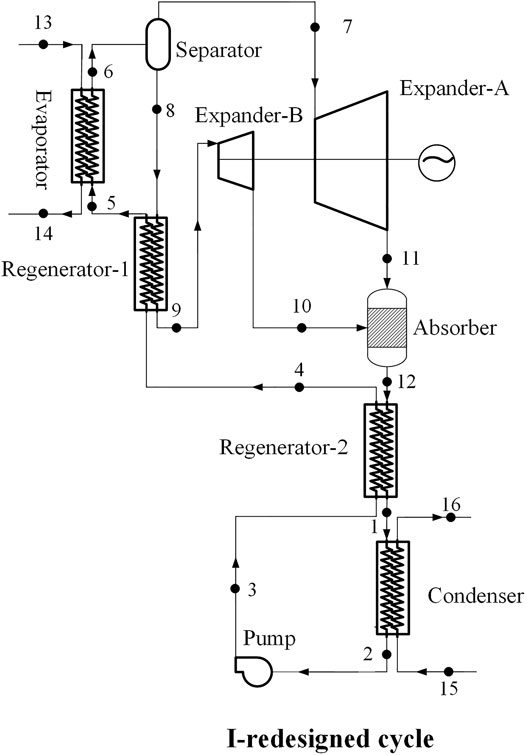
Two redesigned cycles with different placement of SSE, namely the I-redesigned cycle and the II-redesigned cycle, are proposed in this paper. Three cycles studied in this paper are illustrated as follows.
Original KCS 34 with a throttle valve.
I-redesigned cycle: The redesigned KCS 34 with a SSE. The SSE replaces the throttle valve and is placed between the absorber and the regenerator -1.
II-redesigned cycle: The redesigned KCS 34 with an SSE. The SSE is placed between the regenerator -1 and the gas-liquid separator. The throttle valve in the original KCS 34 is removed.
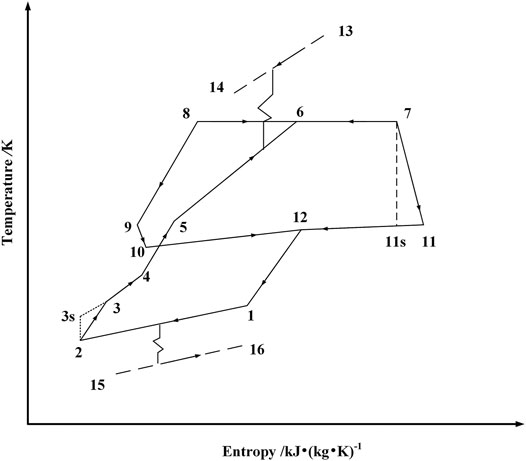
The schematic diagram of the original KCS 34 with a throttle valve is depicted in Figure 1, and its T-s diagram is shown in Figure 2. The ammonia-lean solution at point 8 is throttled to the condensation pressure at state point 10 after flowing through the regenerator-1, and then mixed with the ammonia-rich vapor in the absorber to form a working solution with initial ammonia fraction. The working solution successively flows through regenerator-2 and condenser to reach state point 2. After being pressurized by pump, the working solution flows through the regenerator-2 and the regenerator-1, and then flows into the evaporator. After being heated, the working solution at point 6 is sent to separator, in which it is split into ammonia-rich vapor at point 7 and ammonia-lean solution at point 8. Two redesigned cycles based on the original KCS 34 are depicted in Figure 3 and Figure 4.
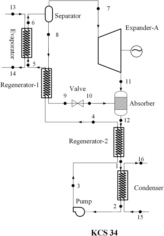
FIGURE 1. The schematic diagram of the original KCS 34 (Mlack, 2002).
General Assumptions
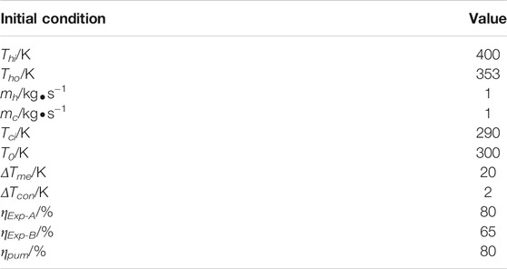
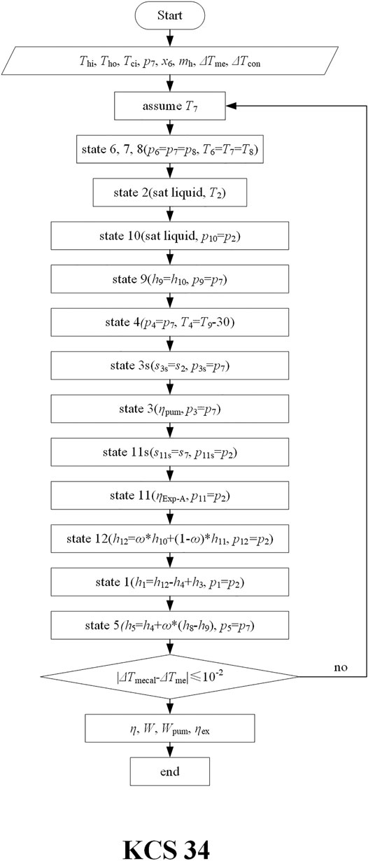
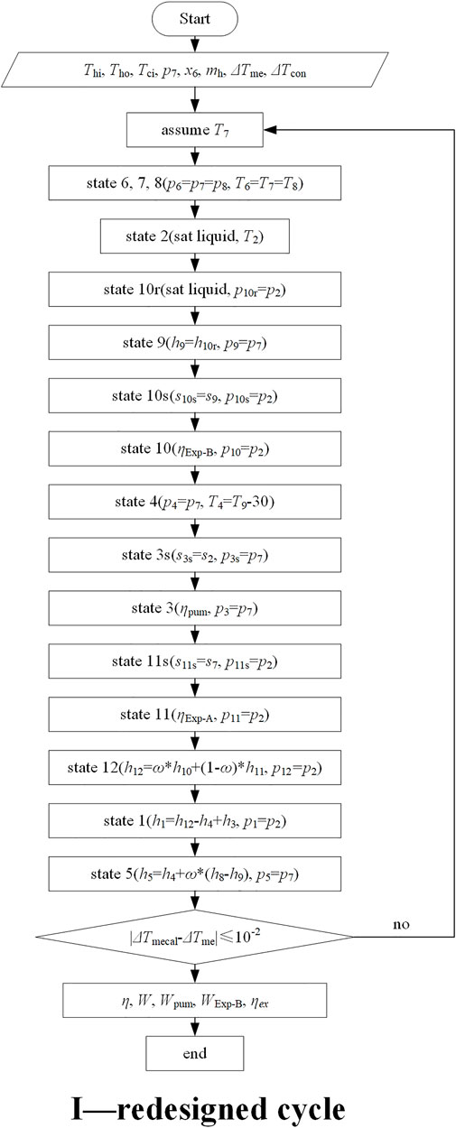
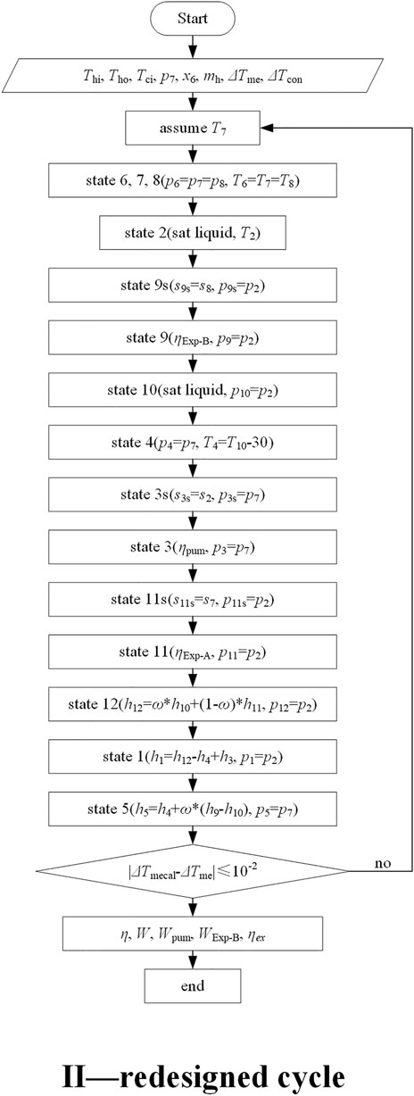
In this paper, the EES (Engineering Equation Solver) software is used to calculate the thermophysical properties of ammonia-water. The logarithmic mean temperature difference in the evaporator is used as the convergence condition in the calculation. Table 1 lists the initial conditions used for calculation. Figure 5, Figure 6, and Figure 7 shows the flowcharts of the calculation programs for the original KCS 34 and its two redesigned cycles. In order to simplify the calculation, the following assumptions are used.
1) The system and its components are at steady states.
2) Pipeline pressure loss and the energy loss caused by fluid friction in the system are neglected.
3) Heat loss in the system is neglected.
4) The isentropic efficiency of the SSE in the two redesigned cycles is equal.
5) The exergy loss of cooling water is neglected.
6) According to engineering experience, the highest pressure in the system is maintained within 3 MPa.
Thermodynamic Analysis
In the cycle, flue gas is used as the heat source, and its inlet and outlet temperatures are T13 and T14, respectively. The heat input of the system is
Heat exchanged in condenser and regenerators is
Work produced by expander A is
Work produced by SSE B is
For I—redesigned cycle
For Ⅱ—redesigned cycle
Power consumed by pump is
Net work output of system is
Thermal efficiency is
Exergy at the inlet of heat source is
Where Tmh is the average temperature of heat source.
Exergy efficiency of the system is defined as the ratio of the net work of the system to the exergy at the inlet of the heat source,
The logarithmic mean temperature difference (LMTD) in evaporator is
Results and Discussion
When neglecting the pressure drop of the working fluid in absorber, heat exchanger, and pipeline, there are only two pressures in the KCS 34, namely evaporation pressure and condensation pressure. For KCS 34, the condensation pressure is determined by the given cooling conditions and ammonia-water concentration. The inlet and outlet temperatures of the separator (T6, T7 and T8) are considered equal. Therefore, this paper discusses the influences of the ammonia-water concentration (x6) and evaporation pressure (p7) on the cycle thermal efficiency, net work, work produced by SSE B, and system exergy efficiency.
Figure 8 depicts the variation of cycle thermal efficiency and net work with the evaporation pressure and ammonia-water concentration for the original KCS 34 and its two redesigned cycles. It can be seen from Figure 8 that the thermal efficiency and net work of the I-redesigned cycle and the II-redesigned cycle are higher than those of the original KCS 34, but the difference between the I-redesigned cycle and the original KCS 34 is small. When the evaporation pressure is 1.5 MPa and the ammonia-water concentration is 0.6, the thermal efficiency of the II-redesigned cycle is 8.5% higher than that of the original KCS 34, while the thermal efficiency of the I-redesigned cycle is only 0.74% higher than that of the original KCS 34. Since the working fluid releases a large amount of energy in the regenerator−1 before entering the SSE B, the cycle thermal efficiency of the I-redesigned cycle is very close to that of the original KCS 34. When the evaporation pressure is low, with the increase of ammonia-water concentration, the cycle thermal efficiency and net work of the three cycles gradually decrease, and the difference among the three cycles also gradually decrease. Therefore, in the case of low pressure, the SSE B does not play a positive role as the ammonia-water concentration increases. When the evaporation pressure is relatively high, the thermal efficiencies of the three cycles are relatively high and the net work large. The decreasing trend of the thermal efficiency and net work of the three cycles gradually slowed down.
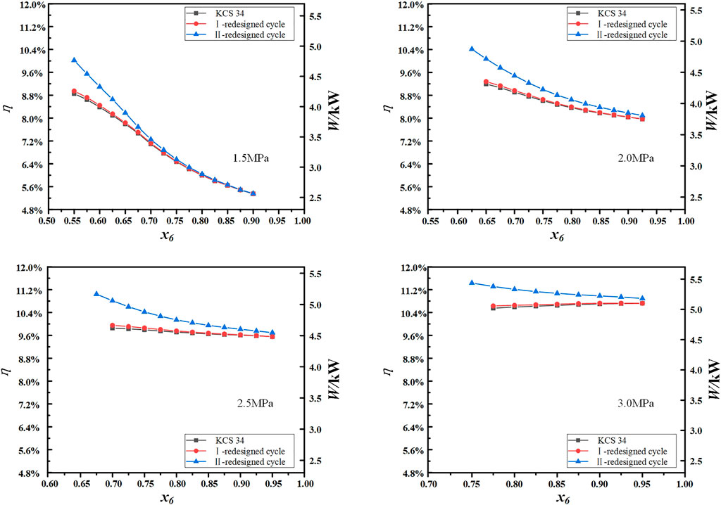
FIGURE 8. The variation of cycle thermal efficiency and net work with the evaporation pressure and ammonia-water concentration.
Figure 9 depicts the variation of the work produced by SSE B with the evaporation pressure and ammonia-water concentration in the I—and II—redesigned cycles. It can be seen from Figure 9 that the work produced by the SSE B in the II-redesigned cycle is higher than that produced by the SSE B in the I-redesigned cycle. When the evaporation pressure is 1.5 MPa and ammonia-water concentration varies from 0.55 to 0.8, the work produced by SSE B in the II-redesigned cycle is 5–12 times that of SSE B in the I-redesigned cycle. With the concentration increase of ammonia-water, the mass flow of working fluid in the path of ammonia-lean solution gradually decreases, so the work produced by the SSE B in the two redesigned cycles gradually decreases, and the difference between the work produced in two redesigned cycles also gradually decreases.
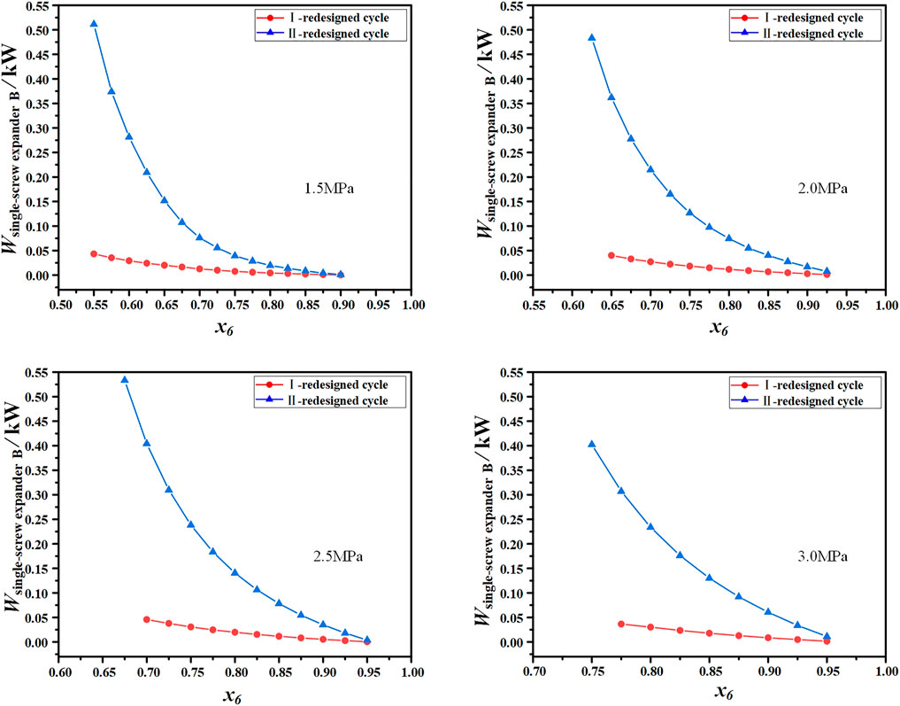
FIGURE 9. The variation of the work produced by SSE B with the evaporation pressure and ammonia-water concentration in the I- and II-redesigned cycles.
Figure 10 depicts the variation of exergy efficiency of three cycles with the evaporation pressure and ammonia-water concentration. Since the inlet and outlet temperatures and flow rates of the flue gas in three cycles are given and their values are the same, exergy efficiency has a similar variation trend to thermal efficiency and net work. Compared with the low cycle thermal efficiencies of three cycles shown in Figure 8, their cycle exergy efficiencies are higher. The highest cycle exergy efficiency of 56.59% can be obtained in the II-redesigned cycle when the evaporation pressure is 3.0 MPa and ammonia-water concentration is 0.75.
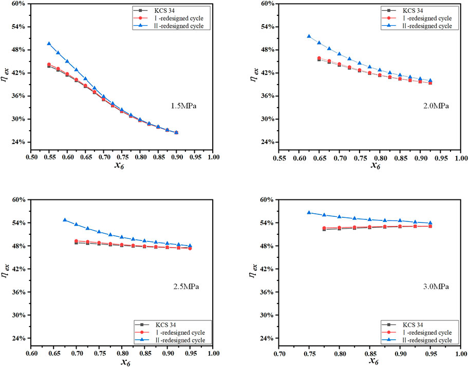
FIGURE 10. The variation of exergy efficiency with the evaporation pressure and ammonia-water concentration.
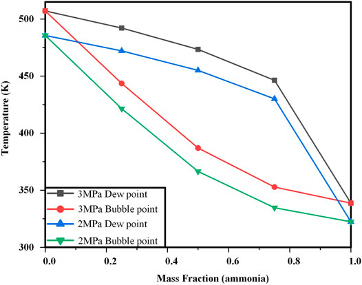
In general, through the above analysis, it can be seen that the performance of the II-redesigned cycle is better than that of the I-redesigned cycle, especially when ammonia-water concentration is moderate. This can be explained by the non-isothermal evaporation characteristics of ammonia-water. Figure 11 depicts temperature glides of ammonia-water with the ammonia fraction when the evaporation pressures are 2 and 3 MPa, respectively. When the ammonia fraction is moderate, the evaporation temperature glide of ammonia-water is greatest, so it matches the heat source best. While when the ammonia-water concentration is very low or very high, it is closer to pure water or pure ammonia, which leads to a small temperature glide.
Conclusion
In order to recover the energy loss due to throttling in the path of the ammonia-lean solution in the Kalina Cycle System (KCS) 34, two redesigned cycles, namely I-redesigned cycle and II-redesigned cycle, in which SSEs that can perform two-phase expansion are used to replace the throttle valve, are proposed in this paper. In the I-redesigned cycle, the SSE replaces the throttle valve and is placed between the absorber and the regenerator -1. In the II-redesigned cycle, the SSE is placed between the gas-liquid separator and the regenerator -1. The throttle valve between the absorber and the regenerator-1 in the original KCS 34 is removed.
The thermodynamic performance of two redesigned cycles which have different placement of SSEs is analyzed and compared with the original KCS 34, the following conclusions have been drawn.
1) The cycle thermal efficiency and net work of the I-redesigned cycle and the II-redesigned cycle are higher than those of the original KCS 34, but the difference between the I-redesigned cycle and the original KCS 34 is small.
2) When the evaporation pressure is small, with the increase of ammonia-water concentration, the cycle thermal efficiency and net work of the three cycles gradually decrease, and the difference among the three cycles also gradually decrease. Therefore, in the case of low pressure, the SSE B does not play a positive role as the ammonia-water concentration increases. When the evaporation pressure is relatively high, the thermal efficiency of the three cycles are relatively high and the net work large. The decreasing trend of the thermal efficiency and net work of the three cycles gradually slowed down.
3) The work produced by the SSE B in the II-redesigned cycle is higher than that produced by the SSE B in the I-redesigned cycle. With the concentration increase of ammonia-water, the mass flow of working fluid in the path of ammonia-lean solution gradually decreases, so the work produced by the SSE B in the two redesigned cycles gradually decreases, and the difference between the work produced in two redesigned cycles also gradually decreases.
4) Compared with the low cycle thermal efficiencies of three systems, their cycle exergy efficiencies are higher. The highest cycle exergy efficiency of 56.59% can be obtained in the II-redesigned cycle when the evaporation pressure is 3.0 MPa and ammonia-water concentration is 0.75.
Data Availability Statement
The original contributions presented in the study are included in the article, further inquiries can be directed to the corresponding author.
Author Contributions
XZ and ZL conceptualized the idea. ZL and XZ performed data analysis and formal analysis. XZ and ZL wrote the original draft. YW, CM, and JW obtained resources. XZ and JW reviewed and edited the paper. XZ involved in research project administration and funding acquisition.
Funding
The authors acknowledge the funding of the National Natural Science Foundation of China (Grant No. 51506001).
Conflict of Interest
The authors declare that the research was conducted in the absence of any commercial or financial relationships that could be construed as a potential conflict of interest.
Publisher’s Note
All claims expressed in this article are solely those of the authors and do not necessarily represent those of their affiliated organizations, or those of the publisher, the editors and the reviewers. Any product that may be evaluated in this article, or claim that may be made by its manufacturer, is not guaranteed or endorsed by the publisher.
References
Cao, L., Wang, J., and Dai, Y. (2014). Thermodynamic Analysis of a Biomass-Fired Kalina Cycle with Regenerative Heater. Energy 77, 760–770. doi:10.1016/j.energy.2014.09.058
Eller, T., Heberle, F., and Brüggemann, D. (2017). Second Law Analysis of Novel Working Fluid Pairs for Waste Heat Recovery by the Kalina Cycle. Energy 119, 188–198. doi:10.1016/j.energy.2016.12.081
Gholamian, E., and Zare, V. (2016). A Comparative Thermodynamic Investigation with Environmental Analysis of SOFC Waste Heat to Power Conversion Employing Kalina and Organic Rankine Cycles. Energ. Convers. Manage. 117, 150–161. doi:10.1016/j.enconman.2016.03.011
He, M., Zhang, X., Zeng, K., and Gao, K. (2011). A Combined Thermodynamic Cycle Used for Waste Heat Recovery of Internal Combustion Engine. Energy 36 (12), 6821–6829. doi:10.1016/j.energy.2011.10.014
He, W., Wu, Y., Peng, Y., Zhang, Y., Ma, C., and Ma, G. (2013). Influence of Intake Pressure on the Performance of Single Screw Expander Working with Compressed Air. Appl. Therm. Eng. 51 (1-2), 662–669. doi:10.1016/j.applthermaleng.2012.10.013
Júnior, E. P. B., Arrieta, M. D. P., Arrieta, F. R. P., and Silva, C. H. F. (2019). Assessment of a Kalina Cycle for Waste Heat Recovery in the Cement Industry. Appl. Therm. Eng. 147, 421–437. doi:10.1016/j.applthermaleng.2018.10.088
Kalina, A. I. (1983). Combined Cycle and Waste Heat Recovery Power Systems Based on a Novel Thermodynamic Energy Cycle Utilizing Low-Temperature Heat for Power Generation, Proceedings of the Joint Power Generation Conference: GT Papers American Society of Mechanical Engineers ASME, 25 Sep 1983, Indianapolis, United States. 83, JPGC-GT-3, 1–5. doi:10.1115/83-jpgc-gt-3
Kalina, A. I. (1984). Combined-cycle System with Novel Bottoming Cycle. J. Eng. Gas Turbines Power 106 (4), 737–742. doi:10.1115/1.3239632
Kalina, A. I. (1982). Generation of Energy by Means of a Working Fluid, and Regeneration of a Working Fluid. United States Patent 4346561 (Accessed Aug 31, 1982)
Khankari, G., Munda, J., and Karmakar, S. (2016). Power Generation from Condenser Waste Heat in Coal-Fired thermal Power Plant Using Kalina Cycle. Energ. Proced. 90, 613–624. doi:10.1016/j.egypro.2016.11.230
Lei, B., Wang, W., Wu, Y.-T., Ma, C.-F., Wang, J.-F., Zhang, L., et al. (2016). Development and Experimental Study on a Single Screw Expander Integrated into an Organic Rankine Cycle. Energy 116, 43–52. doi:10.1016/j.energy.2016.09.089
Li, G., Lei, B., Wu, Y., Zhi, R., Zhao, Y., Guo, Z., et al. (2018). Influence of Inlet Pressure and Rotational Speed on the Performance of High Pressure Single Screw Expander Prototype. Energy 147, 279–285. doi:10.1016/j.energy.2018.01.034
Li, X., Zhang, Q., and Li, X. (2013). A Kalina Cycle with Ejector. Energy 54, 212–219. doi:10.1016/j.energy.2013.03.040
Loni, R., Najafi, G., Bellos, E., Rajaee, F., Said, Z., and Mazlan, M. (2021). A Review of Industrial Waste Heat Recovery System for Power Generation with Organic Rankine Cycle: Recent Challenges and Future Outlook. J. Clean. Prod. 287. 125070. doi:10.1016/j.jclepro.2020.125070
Marston, C. H. (1990). Parametric Analysis of the Kalina Cycle. J. Eng. Gas Turbines Power 112 (1), 107–116. doi:10.1115/1.2906464
Mlcak, H. A. (2002). Kalina Cycle Concepts for Low Temperature Geothermal. Geothermal Resour. Counc. Trans. 26, 707–713.
Murugan, R., and Subbarao, P. (2008). Thermodynamic Analysis of Rankine-Kalina Combined Cycle. Int. J. Thermodynamics 11 (3), 133–141.
Prananto, L. A., Zaini, I. N., Mahendranata, B. I., Juangsa, F. B., Aziz, M., and Soelaiman, T. A. F. (2018). Use of the Kalina Cycle as a Bottoming Cycle in a Geothermal Power Plant: Case Study of the Wayang Windu Geothermal Power Plant. Appl. Therm. Eng. 132, 686–696. doi:10.1016/j.applthermaleng.2018.01.003
Sadeghi, S., Saffari, H., and Bahadormanesh, N. (2015). Optimization of a Modified Double-Turbine Kalina Cycle by Using Artificial Bee Colony Algorithm. Appl. Therm. Eng. 91, 19–32. doi:10.1016/j.applthermaleng.2015.08.014
Singh, O. K., and Kaushik, S. C. (2013). Energy and Exergy Analysis and Optimization of Kalina Cycle Coupled with a Coal Fired Steam Power Plant. Appl. Therm. Eng. 51, 787–800. doi:10.1016/j.applthermaleng.2012.10.006
Wall, G., Chuang, C. C., and Ishida, M. (1989). Exergy Study of the Kalina Cycle, Proceedings of the Winter Annual Meeting (WAM), 10 December 1989, San Francisco, California American Society of Mechanical Engineers ASME,
Wang, E., Yu, Z., and Zhang, F. (2017). Investigation on Efficiency Improvement of a Kalina Cycle by Sliding Condensation Pressure Method. Energ. Convers. Manage. 151, 123–135. doi:10.1016/j.enconman.2017.08.078
Wang, J., Yan, Z., Zhou, E., and Dai, Y. (2013a). Parametric Analysis and Optimization of a Kalina Cycle Driven by Solar Energy. Appl. Therm. Eng. 50 (1), 408–415. doi:10.1016/j.applthermaleng.2012.09.002
Wang, W., Wu, Y.-t., Ma, C.-f., Liu, L.-d., and Yu, J. (2011). Preliminary Experimental Study of Single Screw Expander Prototype. Appl. Therm. Eng. 31 (17-18), 3684–3688. doi:10.1016/j.applthermaleng.2011.01.019
Wang, W., Wu, Y.-t., Ma, C.-f., Xia, G.-d., and Wang, J.-f. (2013b). Experimental Study on the Performance of Single Screw Expanders by gap Adjustment. Energy 62, 379–384. doi:10.1016/j.energy.2013.09.031
Wu, Y., Guo, Z., Lei, B., Shen, L., Zhi, R., et al. (2019). Internal Volume Ratio Optimization and Performance Analysis for Single-Screw Expander in Small-Scale Middle Temperature ORC System. Energy 186, 115799. doi:10.1016/j.energy.2019.07.129
Zhang, X., Zhang, Y., Cao, M., Wang, J., Wu, Y., and Ma, C. (2019). Working Fluid Selection for Organic Rankine Cycle Using Single-Screw Expander. Energies 12 (16), 3197. doi:10.3390/en12163197
Zheng, D., Chen, B., Qi, Y., and Jin, H. (2006). Thermodynamic Analysis of a Novel Absorption Power/cooling Combined-Cycle. Appl. Energ. 83 (4), 311–323. doi:10.1016/j.apenergy.2005.02.006
Glossary
Variables
c specific heat, kJ·kg−1·K−1
E exergy, kJ·kg−1
h enthalpy, kJ·kg−1
m mass flow rate, kg·s−1
Q heat quantity, kW
s entropy, kJ·kg−1·K−1
T temperature, K
W power, kW
x ammonia-water concentration
ΔTcon pinch temperature difference for condenser, K
ΔTme logarithmic mean temperature difference, K
ΔTmecal calculated logarithmic mean temperature difference, K
Abbreviations
KCS Kalina Cycle System
ORC Organic Rankine Cycle
SSE single-screw expander
Greek symbol
η thermal efficiency
ηex exergy efficiency
ηExp-A isentropic efficiency of expander A
ηExp-B isentropic efficiency of expander B
ηpum isentropic efficiency of pump
ω concentration of ammonia-water at state point 9
Subscripts
c condenser
ci condenser inlet
con condenser
eva evaporator
h heat source
hi heat source inlet
ho heat source outlet
pum pump
reg-1 regenerator-1
reg-2 regenerator-2
wf working fluid
Keywords: kalina cycle system (KCS)34, single-screw expander, throttle valve, thermodynamic performance, ammonia-water concentration
Citation: Zhang X, Li Z, Wang J, Wu Y and Ma C (2021) Performance Improvement of KCS (Kalina Cycle System) 34 by Replacing Throttle Valve With Single-Screw Expander. Front. Energy Res. 9:741704. doi: 10.3389/fenrg.2021.741704
Received: 15 July 2021; Accepted: 23 September 2021;
Published: 18 October 2021.
Edited by:
Zisheng Lu, Shanghai Jiao Tong University, ChinaCopyright © 2021 Zhang, Li, Wang, Wu and Ma. This is an open-access article distributed under the terms of the Creative Commons Attribution License (CC BY). The use, distribution or reproduction in other forums is permitted, provided the original author(s) and the copyright owner(s) are credited and that the original publication in this journal is cited, in accordance with accepted academic practice. No use, distribution or reproduction is permitted which does not comply with these terms.
*Correspondence: Xinxin Zhang, eGlueGluemhhbmdAYmp1dC5lZHUuY24=
 Xinxin Zhang
 Zhenlei Li
 Jingfu Wang1,2