 Warat Sriwannarat1Pattasad Seangwong2Apirat Siritaratiwat2
 Nuwantha Fernando3Yuttana Dechgummarn2
 Pirat Khunkitti2*
- 1Department of Electrical and Computer Engineering, Kasetsart University Chalermphakiet Sakon Nakhon Campus, Sakon Nakhon, Thailand
- 2Department of Electrical Engineering, Faculty of Engineering, Khon Kaen University, Khon Kaen, Thailand
- 3School of Engineering, Royal Melbourne Institute of Technology (RMIT), Melbourne, VIC, Australia
This paper introduces the pole ratio adjustment technique to improve the torque characteristics of the doubly salient permanent magnetic machine (DSPM). The electrical characteristics of the machine, namely the magnetic field distribution, flux linkage, back-electromotive force (EMF), and cogging torque, were obtained under open-circuit conditions. The electromagnetic torque and ripple torque were examined under the loaded condition. The simulations, based on the 2D-finite element method, show that the optimal pole ratio for the DSPM structure is with 18 stator teeth and 15 rotor poles. This optimal structure achieves a larger phase back-EMF than the conventional structure, as well as had a better magnetic flux path with a reasonable cogging torque. The on-load test also confirmes that the proposed optimal structure can produce a significantly higher electromagnetic torque than the conventional machine while maintaining a satisfactory torque ripple. Furthermore, an experimental prototype of the DSPM structure having 18/15 stator/rotor poles was fabricated and tested to verify the simulations. The experimental results were in good agreement with the simulations. The design technique and the fabricated prototype demonstrate the DSPM utilization for low-speed/high torque applications.
Introduction
Permanent magnet (PM) machines have been extensively researched due mainly to their outstanding merits, such as no excitation loss, low copper loss, high reliability, high electromotive force (EMF) and torque density (Chau et al., 2008; Ibrahim et al., 2015; Okedu et al., 2021). Stator-PM machine is one of the popular type of PM machines, it contains the installed PMs in the stator part (Cheng et al., 2011). The stator-PM machine can be categorized into three main types, i.e., the flux reversal PM machine, the flux switched PM machine, and the doubly salient PM machine (DSPM) (Wang et al., 2001; Zhu, 2011). From literature, it is obviously shown that the DSPM receives much research attention and is suitable for several low-speed applications. The structure of DSPM was inspired by using the PMs attached in the reluctance motor structure (Liao et al., 1995). The DSPM structure contains the PMs mounted in the stator yoke, windings installed on the salient stator poles, while its rotor is a salient pole with no windings or brushes. Based on the configuration of DSPM, this machine indicates low inertia and light rotor weight; therefore it is suitable for low-speed operation (Cheng et al., 2001a; Cheng et al., 2001b). Many previous studies have attempted to develop the DSPM aiming to be used for electric vehicle applications as well as electrical generation from renewable energy which is a clean energy source (Fan et al., 2006; Boonluk et al., 2020; Srithapon et al., 2020; Boonluk et al., 2021; Okedu and Barghash, 2021; Srithapon et al., 2021).
From the literature survey, several design techniques have been proposed to improve the machine performance of the DSPM, i.e., stator doubly-fed technique, stator yoke adjustment, partitioned-stator technique, square envelope structure, and asymmetrical-pole structure. In 2003, the stator doubly-fed technique was reported by Chau et al., (2003) aiming to improve the performance of DSPM through an extra magnetic flux path. In 2015, the partitioned-stator technique was proposed and applied to the DSPM to reduce PM deterioration (Wu et al., 2015). The results revealed that this technique highly improves the structure’s torque density. After that, the PM arrangement technique was applied to the DSPM to enhance the back-EMF (Zhu et al., 2015). Next, the square envelope and asymmetrical-pole techniques were introduced for achieving larger slot area and lower torque ripple of DSPM (Zhang et al., 2019; Xu et al., 2020). Recently, several structural design techniques have been performed to improve the performance of DSPM, i.e., stator pole configuration design (Sriwannarat et al., 2018; Lounthavong et al., 2019; Lounthavong et al., 2020), partitioned-stator with asymmetrical pole (Sriwannarat et al., 2020a), optimizing the number of poles Sriwannarat et al. (2019) and pole configuration adjustment technique (Sriwannarat et al., 2020b).
Based on the literature review, it is obviously demonstrated that the configuration of the machine pole, such as the number of poles, pole shape, pole’s potision and installed magnets, are influential parameters that relate to the machine’s performance. Therefore, this paper aims to improve the performance of DSPM focusing on the torque characteristics, using the pole ratio adjustment technique. The 2-D finite element method (FEM) simulations were performed in the design phase. The electrical characteristics of the machine, consisting of the magnetic field distribution, flux linkage, back-EMF, and cogging torque, were investigated under no-load condition. The electromagnetic torque and its ripple were examined under on-load condition. The optimal structure designed in this work was selected for prototype fabrication. The experimental measurement was performed to validate the simulations.
Machine Design and Fabrication
In this study, we proposedly improve the performance of DSPM by using the pole ratio adjustment technique. The conventional structure focused in this work was adopted by Wu et al. (2015), as shown in Figure 1B. It is the DSPM that has 12 stator poles and 10 rotor poles, which can be written as 12/10 poles. The stator yoke of this structure contains the mounted PMs for magnetic field excitation. Salient stator teeth are wound by the copper winding coil. The number of PM is set to be equal to the stator teeth. This conventional structure was claimed as an efficient DSPM structure.
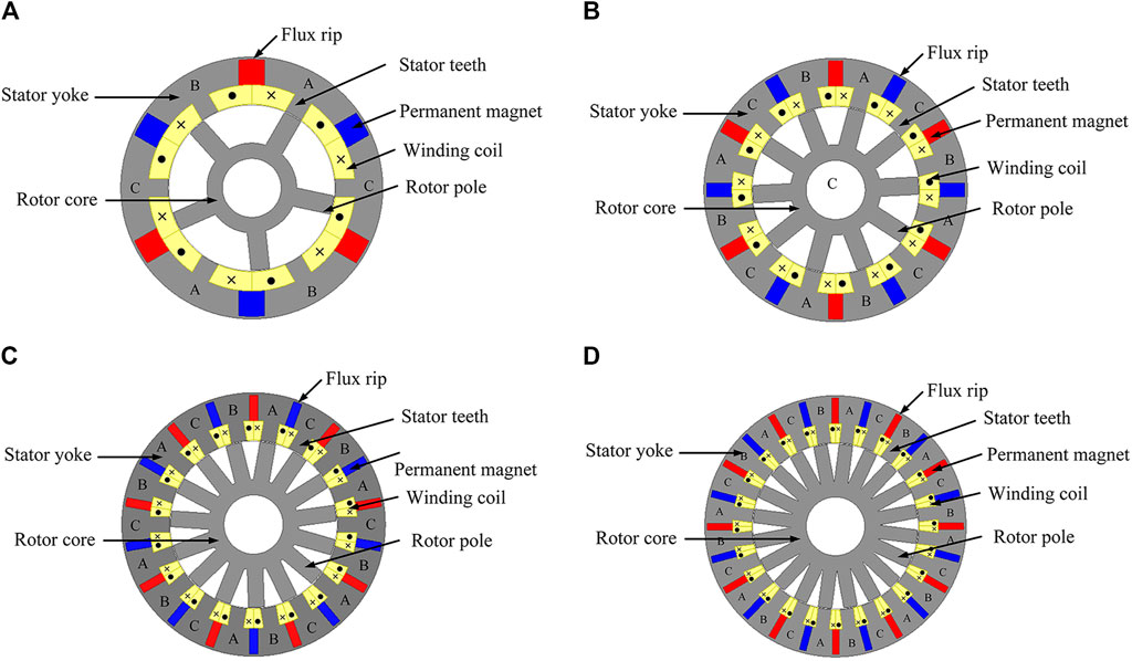
FIGURE 1. The cross-sectional perspective of DSPM with (A) 6/5, (B) conventional 12/10, (C) 18/15, and (D) 24/20-poles.
To improve the performance of the DSPM, the design process starts from the formulas to initialize the stator and rotor pole number of the traditional DSPM which is introduced by Fan et al. (2006), as given in (1).
Where Ns is number of stator teeth, Nr is number of rotor poles, m is the phase number, and k is a positive integer. The advantages of this ratio are the small solid loss of structure due to the higher number of stator teeth than the rotor poles. After that, Wu et al. (2015) performed these formulas to their proposed DSPM machines, they found that the conventional formulas could cause asymmetrical and non-sinusoidal back-EMF waveform. Accordingly, they have proposed that the suitable stator/rotor pole numbers of DSPM should be 12/10 instead of 12/8 obtained by the traditional formulas. Their proposed DSPM having 12/10 stator/rotor poles demonstrated a better electromagnetic performance, and therefore was selected as the conventional in this work. To further develop the performance of this conventional structure, we firstly normalized the number of stator/rotor poles of the conventional structure to a ratio of 6 n/5 n where n is an integer. Then, this normalized ratio varied with increasing n from 1 to 4. This resulted in DSPM designs having 6/5 (n = 1) poles, 18/15 (n = 3) poles, and 24/20 (n = 4) poles, while the conventional structure was 12/10 (n = 2) poles, as shown in Figure 1. The configuration of each proposed machine was constructed based on the linear order relation of the conventional machine. It is noted that the DSPM structures having an integer n higher than four demonstrated a significantly worse performance and were not considered in our evaluation. The overall design process is detailly summarized in the flowchart shown in Figure 2. Design parameters of all proposed structures are shown in Table 1. The total PMs volume of all structures were set to be equal for a fair comparison, taking into account the magnet dimensions that are available as a product. Also, the 3 mm flux rip was made at the stator yoke of all proposed machines for their experimental potentiality.
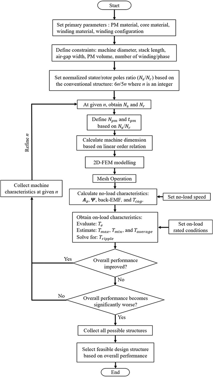
FIGURE 2. A flowchart indicating an optimization design process.
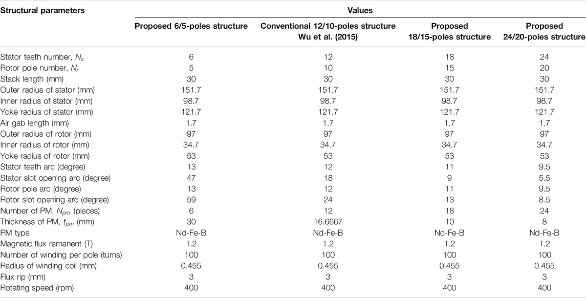
TABLE 1. The structural design parameters of all proposed DSPM.
The performance of all DSPM structures was evaluated through their machine characteristics including magnetic field distribution, magnetic flux-linkage, back-EMF, and cogging toque in an open-circuit test. And then, the electromagnetic torque and ripple torque profiles were examined under on-load condition. The rated speed of machine was fixed to be 400 rpm. The DSPM indicating the best performance was selected for prototype fabrication. Then, the output profiles of the prototype were experimentally measured for to verify the simulation results.
Theory of Machine Analysis
In this section, all related theories used for analysis of machine characteristics are given. The machine characteristics focused in this work include the magnetic field distribution, magnetic flux-linkage, back-EMF, and cogging toque for open-circuit test. Meanwhile, the electromagnetic torque and ripple torque profiles were examined under on-load condition.
Magnetic Field Distribution, Magnetic Flux-Linkage, and Back-EMF
Magnetic flux distribution was firstly examined to monitor the magnetic field flowing through the structure of PM machines. The magnetic field intensity of each magnetic flux path can also be investigated by this parameter. The magnetic vector potential is initiated by the Poisson’s nonlinear partial differential equation, as given in (2);
where
The magnetic flux obtained from the magnetic flux path at each stator tooth,
Where
Cogging Toque
Cogging torque normally indicates the magnetic force locking the rotor rotation at no-load initial state. It occurs by an interaction between the PMs of stator teeth and rotor segment. The magnitude of cogging torque,
Electromagnetic Torque and Ripple
The on-load electromagnetic torque is typically obtained from the interaction between magnetic field in the air gap and surface element of the rotor segment. The expression for electromagnetic torque calculation is shown in (6);
where
where
Simulation Results and Discussion
Open-Circuit Magnetic Field Distribution
The open-circuit magnetic field distribution of the DSPM with 6/5, 12/10, 18/15, and 24/20 poles was firstly evaluated, as illustrated in Figures 3A-D, respectively. The magnetic field density of each structure was also illustrated by color scaling in this figure. It is shown that the magnetic field distribution of all structures is well symmetric. The results also indicate that the number of poles directly impacts the distribution and density of the magnetic field. The machines having larger pole numbers seems to have a higher intensity of the magnetic field due to their narrower pole teeth. A greater number of poles also causes a larger flux leakage in the structure.
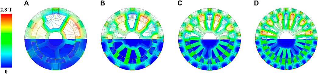
FIGURE 3. Magnetic field distribution of all proposed DSPM structures with (A) 6/5, (B) conventional 12/10, (C) 18/15, and (D) 24/20 poles.
Open-Circuit Phase Flux Linkage and Back-EMF
The flux linkage and back-EMF profiles are generally the important parameters indicating the machine performance. Figures 4A,B show the waveforms of the open circuit phase flux linkage and back-EMF for all machine structures. The conventional 12/10 poles DSPM structure can provide the highest phase flux linkage followed by the 18/15, 6/5, and 24/16-poles structures, respectively. The lowest flux linkage of the 24/16 poles structure was due to its highest flux leakage, as explained in the previous sub-section. The phase back-EMF profile clearly demonstrates that the 18/15 poles DSPM can produce the highest back-EMF, following by the 24/20, 12/10, and 6/5 poles structures. Although the back-EMF waveforms of the 18/15 and 6/5 poles structures slightly contain a harmonic, the harmonic scale is acceptable. The DSPM with 18/15 poles indicates the overall EMF profile in which its magnitude is 9.82% improved from the conventional structure, showing that this structure has a more suitable magnetic flux path than the others.
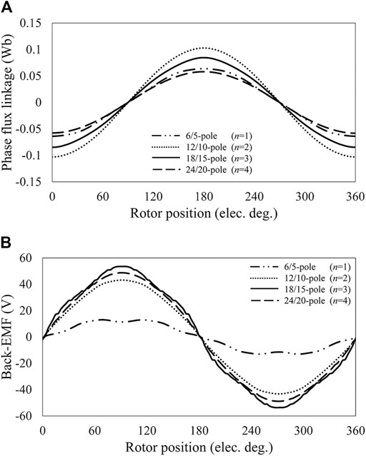
FIGURE 4. The waveforms of (A) phase flux linkage and (B) phase back-EMF of the proposed DSPM structures.
Cogging Torque
The cogging torque waveform of all proposed machines is illustrated in Figure 5. All cogging torque waveforms are well symmetric. The 24/20 poles DSPM structure has the worst cogging torque profile due to the largest number of permanent magnets, meanwhile the cogging torque of other structures is on the same scale. The cogging torque of the 18/15 poles DSPM was slightly worse than the convention structure. Therefore, the open-circuit analysis clearly demonstrates that the DSPM with 18/15 poles not only provides the highest back-EMF magnitude, but the reasonable cogging torque value is also maintained.
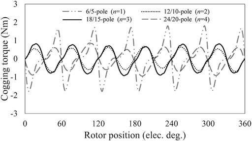
FIGURE 5. The cogging torque waveforms of all proposed DSPM structures.
Electromagnetic Torque Profile
The electromagnetic torque profiles of each the proposed structures was investigated under load conditions at various phase currents, as shown in Figure 6. The rotating speed was assumed to be 400 rpm in this evaluation. It shows that the average torque of all structures is linearly increased with increasing a phase current. Torque of the 18/15 poles structure is enhanced most when the current grows. In particular, we observed that the DSPM having 18/15 poles could produce the highest average torque, followed by the 12/10, 24/20, and 6/5 poles structures, respectively, for all load currents. As displayed in Figure 7 and Table 2, the waveforms of electromagnetic torque were collected at the rated condition of 2 A load current and 400 rpm rotating speed. It was found that the electromagnetic torque of the 18/15 and 6/5 poles structures could slightly suffer from a non-sinusoidal waveform, which is consistent with their EMF profiles. Figure 7B exhibits that although the torque ripple of the 18/15 poles structure was slightly higher than the conventional 12/10 poles DSPM, its reasonable scale was maintained. The average torque against speed curves are depicted in Figure 8 to demonstrate the system variants. As expected, the constant torque value is well observed at all rotating speed for all DSPM machines. Therefore, overall evaluation apparently indicates that the DSPM with 18/15 poles has the best performance and will be chosen for prototype fabrication. By comparing the performance of the proposed 18/15 poles structure to the other existing DSPM machines, it is revealed that the torque density produced by our optimized structure is on a high-range scale.
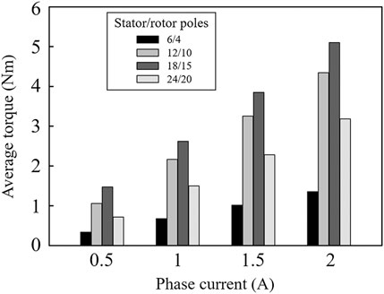
FIGURE 6. Average torque of all proposed DSPM structures at various load currents (400 rpm rotating speed).
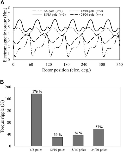
FIGURE 7. (A) Electromagnetic torque waveforms at the load current of 2 A and (B) ripple torque percentage of All proposed DSPM structures (400 rpm rotating speed).
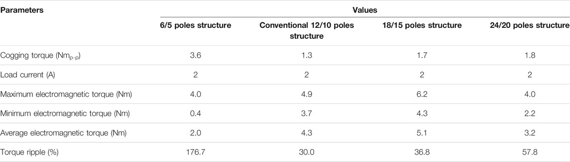
TABLE 2. Torque profiles of the proposed DSPM structures.
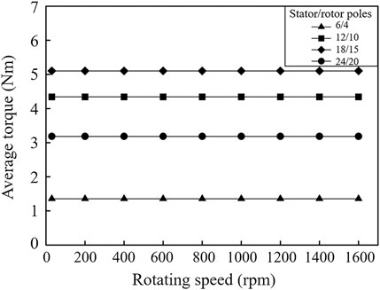
FIGURE 8. Average torque of all proposed DSPM structures at various rotating speed (2 A load current).
Experimental Validation
To verify the simulation results, the prototype of the 18/15 poles DSPM was built, as shown in Figures 9A,B. The prototype was set to be operated at 400 rpm and was tested under open-circuit and on-load conditions. The open-circuit back-EMF waveform of the fabricated machine is shown in Figure 10. It is demonstrated that the machine prototype’s measurement back-EMF waveform is well consistent with the finite element prediction. The slight difference between the two waveforms was due to manufacturing tolerances of fabrication mainly with the inner rotor diameter and other effects due to assembly. However, a good agreement between the two waveforms was verified.
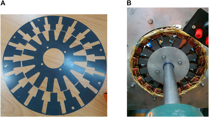
FIGURE 9. The 18/15-poles DSPM prototype machine (A) laminated stator and rotor, and (B) assembled prototype machine.
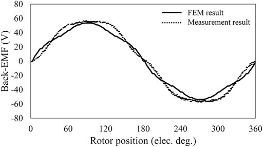
FIGURE 10. The 2-D FEM and measured phase back-EMF of the proposed 18/15-poles DSPM.
Figure 11 presents the on-load experimental setup of the 18/15 poles DSPM prototype. The load current of 2 A was assigned through the resistive loads. The operating speed of 400 rpm was set. As shown in Figure 12A, the measured electromagnetic torque waveform of the machine prototype is compared with the FEM simulation. It indicates that the shape of the measured torque is in good agreement with the simulated result. However, the magnitude of the measurement waveform is slightly smaller than the simulated waveform due to the mechanical and shape tolerances. In addition, Figure 12B demonstrates that the ripple of measured torque waveform is slightly higher than that obtained from the simulation result due to the same reasons. Therefore, the machine characteristics under on-load condition are validated with good agreement.
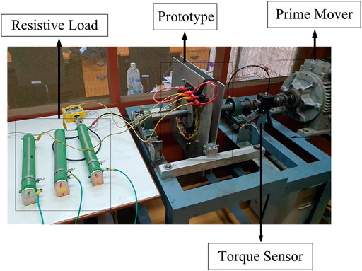
FIGURE 11. Experimental setup of the 18/15-poles DSPM prototype machine.
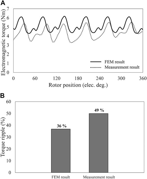
FIGURE 12. The FEM and measurement result of (A) electromagnetic torque and (B) ripple torque at the load current of 2 A of the proposed 18/15-poles DSPM (400 rpm rotating speed).
Conclusion
In this paper, the pole ratio adjustment technique to was introduced to improvethe performance of the DSPM. The electrical characteristics of the machine under open circuit and on-load conditions were examined and analyzed through the finite element method. The simulation results showed that the DSPM structure having 18 stator poles and 15 rotor poles was the optimal structure that indicated the best performance for both open circuit and on-load conditions. The optimal structure could produce a 9.82% higher back-EMF and a 17.94% larger electromagnetic torque than the conventional structure, while a reasonable scale of cogging torque and ripple is maintained. Furthermore, an experimental prototype of the DSPM structure having 18/15 stator/rotor poles was built and tested to verify the simulations. The measurement of machine characteristics was in good agreement with the simulations. The design technique and the fabricated prototype can be utilized for low-speed applications of electrical machines.
Data Availability Statement
The original contributions presented in the study are included in the article/Supplementary Material, further inquiries can be directed to the corresponding author.
Author Contributions
WS did the conceptualization, literature review, simulations analysis, and writing a draft of the manuscript. PS, NF, and YD did a visualization. AS did part of the sponsorship. PK did part of the literature review, sponsorship of the manuscript and Review and editing the manuscript and project administration. All authors contributed to the article and approved the submitted version.
Funding
This work was financially supported by the National Science and Technology Development Agency-Electricity Generating Authority of Thailand Co-funding (FDA-CO-2562-10257-TH), the Provincial Electricity Authority (PEA), and Office of the Ministry of Higher Education, Science, Research and Innovation through Research Grant for New Scholar.
Conflict of Interest
The authors declare that the research was conducted in the absence of any commercial or financial relationships that could be construed as a potential conflict of interest.
Publisher’s Note
All claims expressed in this article are solely those of the authors and do not necessarily represent those of their affiliated organizations, or those of the publisher, the editors and the reviewers. Any product that may be evaluated in this article, or claim that may be made by its manufacturer, is not guaranteed or endorsed by the publisher.
References
Boonluk, P., Khunkitti, S., Fuangfoo, P., and Siritaratiwat, A. (2021). Optimal Siting and Sizing of Battery Energy Storage: Case Study Seventh Feeder at Nakhon Phanom Substation in Thailand. Energies 14, 1458. doi:10.3390/en14051458
Boonluk, P., Siritaratiwat, A., Fuangfoo, P., and Khunkitti, S. (2020). Optimal Siting and Sizing of Battery Energy Storage Systems for Distribution Network of Distribution System Operators. Batteries 6, 56. doi:10.3390/batteries6040056
Chau, K. T., Chan, C. C., and Chunhua Liu, C. (2008). Overview of Permanent-Magnet Brushless Drives for Electric and Hybrid Electric Vehicles. IEEE Trans. Ind. Electron. 55, 2246–2257. doi:10.1109/TIE.2008.918403
Chau, K. T., Jiang, J. Z., and Wang, Y. (2003). A Novel Stator Doubly Fed Doubly Salient Permanent Magnet Brushless Machine. IEEE Trans. Magn. 39, 3001–3003. doi:10.1109/TMAG.2003.816722
Cheng, M., Chau, K. T., and Chan, C. C. (2001a). Design and Analysis of a New Doubly Salient Permanent Magnet Motor. IEEE Trans. Magn. 37, 3012–3020. doi:10.1109/20.947054
Cheng, M., Chau, K. T., and Chan, C. C. (2001b). Static Characteristics of a New Doubly Salient Permanent Magnet Motor. IEEE Trans. Energ. Convers. 16, 20–25. doi:10.1109/60.911398
Cheng, M., Hua, W., Zhang, J., and Zhao, W. (2011). Overview of Stator-Permanent Magnet Brushless Machines. IEEE Trans. Ind. Electron. 58, 5087–5101. doi:10.1109/TIE.2011.2123853
Fan, Y., Chau, K. T., and Cheng, M. (2006). A New Three-Phase Doubly Salient Permanent Magnet Machine for Wind Power Generation. IEEE Trans. Ind. Appl. 42, 53–60. doi:10.1109/TIA.2005.861910
Ibrahim, M., Masisi, L., and Pillay, P. (2015). Design of Variable Flux Permanent-Magnet Machine for Reduced Inverter Rating. IEEE Trans. Ind. Applicat. 51, 3666–3674. doi:10.1109/TIA.2015.2423661
Liao, Y., Liang, F., and Lipo, T. A. (1995). A Novel Permanent Magnet Motor with Doubly Salient Structure. IEEE Trans. Ind. Appl. 31, 1069–1078. doi:10.1109/28.464521
Lounthavong, V., Sriwannarat, W., Seangwong, P., Siritaratiwat, A., and Khunkitti, P. (2020). Optimal Stator Design to Improve the Output Voltage of the Novel Three-Phase Doubly Salient Permanent Magnet Generator. Int. J. Energy Convers. 8, 118–125. doi:10.15866/irecon.v8i4.19302
Lounthavong, V., Sriwannarat, W., Siritaratiwat, A., and Khunkitti, P. (2019). Optimal Stator Design of Doubly Salient Permanent Magnet Generator for Enhancing the Electromagnetic Performance. Energies 12, 3201. doi:10.3390/en12163201
Okedu, K. E., Al Tobi, M., and Al Araimi, S. (2021). Comparative Study of the Effects of Machine Parameters on DFIG and PMSG Variable Speed Wind Turbines During Grid Fault. Front. Energ. Res. 9, 174. doi:10.3389/fenrg.2021.681443
Okedu, K. E., and Barghash, H. (2021). Enhancing the Transient State Performance of Permanent Magnet Synchronous Generator Based Variable Speed Wind Turbines Using Power Converters Excitation Parameters. Front. Energ. Res. 9, 109. doi:10.3389/fenrg.2021.655051
Srithapon, C., Fuangfoo, P., Ghosh, P. K., Siritaratiwat, A., and Chatthaworn, R. (2021). Surrogate-Assisted Multi-Objective Probabilistic Optimal Power Flow for Distribution Network with Photovoltaic Generation and Electric Vehicles. IEEE Access 9, 34395–34414. doi:10.1109/ACCESS.2021.3061471
Srithapon, C., Ghosh, P., Siritaratiwat, A., and Chatthaworn, R. (2020). Optimization of Electric Vehicle Charging Scheduling in Urban Village Networks Considering Energy Arbitrage and Distribution Cost. Energies 13, 349. doi:10.3390/en13020349
Sriwannarat, W., Khunkitti, P., Janon, A., and Siritaratiwat, A. (2018). An Improvement of Magnetic Flux Linkage in Electrical Generator Using the Novel Permanent Magnet Arrangement. Acta Phys. Pol. A. 133, 642–644. doi:10.12693/aphyspola.133.642
Sriwannarat, W., Khunkitti, P., Seangwong, P., Thasnas, N., and Siritaratiwat, A. (2020b). A Novel Asymmetrical-Pole PS-DSPM with Variation of Outer Stator Teeth Number for an Improvement of Electromagnetic Performances. Inter. Jour. Eng. Res. Tech. 13, 1629–1634. doi:10.37624/ijert/13.7.2020.1629-1634
Sriwannarat, W., Seangwong, P., Lounthavong, V., Khunkitti, S., Siritaratiwat, A., and Khunkitti, P. (2020a). An Improvement of Output Power in Doubly Salient Permanent Magnet Generator Using Pole Configuration Adjustment. Energies 13, 4588. doi:10.3390/en13174588
Sriwannarat, W., Siritaratiwat, A., and Khunkitti, P. (2019). Structural Design of Partitioned Stator Doubly Salient Permanent Magnet Generator for Power Output Improvement. Adv. Mater. Sci. Eng. 2019, 2189761. doi:10.1155/2019/2189761
Wang, C. X., Boldea, I., and Nasar, S. A. (2001). Characterization of Three Phase Flux Reversal Machine as an Automotive Generator. IEEE Trans. Energ. Convers. 16, 74–80. doi:10.1109/60.911407
Wu, Z. Z., Zhu, Z. Q., and Shi, J. T. (2015). Novel Doubly Salient Permanent Magnet Machines with Partitioned Stator and Iron Pieces Rotor. IEEE Trans. Magn. 51, 1–12. doi:10.1109/TMAG.2015.2404826
Xu, W., Zhang, Y., Du, G., He, M., and Zhu, J. (2020). No-Load Performance Analysis of an Asymmetric-Pole Single-phase Doubly Salient Permanent Magnet Machine. IEEE Trans. Ind. Electron. 68, 2907–2918. doi:10.1109/TIE.2020.2978686
Zhang, L., Wu, L. J., Huang, X., Fang, Y., and Lu, Q. (2019). A Novel Structure of Doubly Salient Permanent Magnet Machine in Square Envelope. IEEE Trans. Magn. 55, 1–5. doi:10.1109/TMAG.2019.2906772
Zhu, Z. Q., Hua, H., Wu, D., Shi, J. T., and Wu, Z. Z. (2015). Comparative Study of Partitioned Stator Machines with Different PM Excitation Stators. IEEE Trans. Ind. Applicat. 52, 199–208. doi:10.1109/TIA.2015.2477055
Keywords: rotating machine, synchronous machine, permanent magnet machine, doubly salient permanent magnet machine, electromagnetic torque
Citation: Sriwannarat W, Seangwong P, Siritaratiwat A, Fernando N, Dechgummarn Y and Khunkitti P (2021) Electromagnetic Torque Improvement of Doubly Salient Permanent Magnet Machine Using Pole Ratio Adjustment Technique. Front. Energy Res. 9:726164. doi: 10.3389/fenrg.2021.726164
Received: 16 June 2021; Accepted: 03 August 2021;
Published: 26 August 2021.
Edited by:
Sudhakar Babu Thanikanti, Chaitanya Bharathi Institute of Technology, IndiaReviewed by:
Kenneth. E. Okedu, National University of Science and Technology, OmanWei Hu, Zhejiang University, China
Copyright © 2021 Sriwannarat, Seangwong, Siritaratiwat, Fernando, Dechgummarn and Khunkitti. This is an open-access article distributed under the terms of the Creative Commons Attribution License (CC BY). The use, distribution or reproduction in other forums is permitted, provided the original author(s) and the copyright owner(s) are credited and that the original publication in this journal is cited, in accordance with accepted academic practice. No use, distribution or reproduction is permitted which does not comply with these terms.
*Correspondence: Pirat Khunkitti, cGlyYXRraEBra3UuYWMudGg=