- School of Automation Engineering, Northeast Electric Power University, Jilin, China
In this article, a method to improve refractive index (RI) sensitivity of single‐mode–no core–single‐mode fiber (SNS) sensor structure is addressed by optimization of geometric parameters of no-core fiber (NCF), which could be used to accurately measure the irreversible deformation of the battery expansion state caused by temperature change. From the perspective of temperature changing RI of the electrolyte solution, the impacts of diameter, length, and waveband on the performance of the fiber sensor have been discussed as RI measurement range is 1.340–1.390. After optimization, RI sensitivity can reach approximately 2,252.7 and 2037.3 nm/RIU with the length of 6.55 and 6.75 mm when the RI is from 1.380 to 1.390.
Introduction
Optical fiber sensor is widely applied in industry, medical treatment, energy storage, aerospace, and other fields for sensing measurement due to its anti-electromagnetic interference, small size, easy access, etc. Single-mode–multimode–single-mode fiber (SMS) structure based on multimode interference (MMI) has been used for strain (May-Arrioja et al., 2016; Zhou et al., 2008), temperature (Tripathi et al., 2009; Su et al., 2014; Han et al., 2014; Zhang et al., 2013; Li et al., 2006), humidity (An et al., 2014), and RI (Zhao et al., 2015; Zhang et al., 2020; Zhao et al., 2014) measurement in harsh environment. Compared with SMS, SNS structure can directly sense changes of its surrounding RI, and there is no need to strip or corrode the cladding of multimode fiber (MMF) using hydrofluoric acid. The geometric parameters of the waveguide structure based on MMI and RI measurement range have a great effect on sensing sensitivity (Qiang et al., 2011). The RI sensitivity of SNS reflective structure with the range of 1.330–1.380 is 141 nm/RIU (Zhou et al., 2015) and 327 nm/RIU when the reflective structure is based on single-mode–multimode structure (S-M) coating gold layer with small NCF diameter (Zhou et al., 2017). It illustrates again that RI sensitivity of SNS structure can be improved by optimizing NCF’s geometric parameters.
However, there are few reports on structural parameter optimization or the analysis process of SNS sensor. Meanwhile, in view of the huge research space for expansion and deformation of lithium batteries when overcharged, lithium batteries tend to have many internal chemical reactions before and after expansion to release a large amount of heat (Wang et al., 2014; Yan et al., 2018; Zla, et al., 2020; Maleki and Howard, 2006; Shin et al., 2002). The higher the temperature, the more obvious is the bulging degree of battery. If not controlled, it is easy to evolve into the phenomenon of lithium battery thermal runaway (Feng et al., 2017; Liang et al., 2021). Since the sensitivity of SNS structure with temperature change is insufficient in this study, the real-time monitoring of fine temperature changes cannot be performed using SNS structure (Chen et al., 2015). Therefore, the idea of predicting the battery expansion degree by monitoring the variation of RI caused by surrounding temperature with SNS structure is proposed.
Materials and Methods
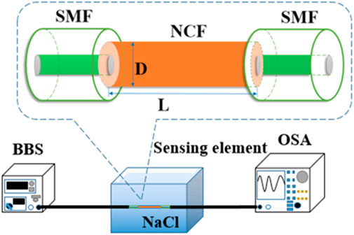
In order to improve RI sensitivity, the key point of SNS structural parameter optimization is to apply low-cost and easily accessible NaCl with concentration of 5–25%, instead of electrolyte solution to monitor the RI varying from 1.340 to 1.390 (Li et al., 2012; Wang et al., 2016). The schematic diagram of SNS structure sensing is shown in Figure 1.
In SNS structure, the single-mode fiber (SMF) is Corning SMF-28e with core diameter of 8.2 μm, cladding diameter of 125 μm, core RI of 1.45, and cladding RI of 1.444. Since the normalized power of SNS structure is higher when the length of NCF is a multiple of self-imaging period, the wavelength shift of the interference peak in the transmission spectrum can be easily observed at this time. And the smaller the NCF diameter, more energy will transmit into the surrounding liquid material in the form of evanescent wave (Wu et al., 2007; Tan et al., 2013). Besides, RI sensitivity is closely related to the sensing waveband. Therefore, SNS structure with higher RI sensitivity can be obtained within a certain waveband by continuously optimizing the geometric parameters of NCF.
At first, the initial diameter Dcore of NCF is 125 μm, the appropriate initial length L1 of NCF is 15 mm obtained from the self-imaging period. Then, the diameter D1 is optimized according to RI sensitivity of SNS structure and the curve overlap of different RI in a certain diameter’s transmission spectrum. The values of L1 and D1 are large, and RI sensitivity is not ideal at this moment, so it is called the initial rough optimization. For the secondary meticulous optimization, the length L2 is optimized based on the self-imaging period to achieve higher RI sensitivity of SNS structure when the diameter is D1. On the premise of L2 and D1, a smaller diameter D2 can be optimized again by analyzing RI sensitivity and the spectral line overlap phenomenon of transmission spectrum. Since SNS structure’s self-imaging period is different with different NCF diameters, length optimization is carried out again on the basis of D2. Considering that L2 is already short, the value of optimized length L3 should be close to L2, and then another diameter optimization can be avoided. After the geometrical parameters of NCF are finally determined, RI sensitivity is re-analyzed by changing waveband.
In addition, the effect of SMF parameters on RI sensitivity should also be considered. Then, the diameter of SMF and the difference of RI square between the core and cladding are finally simply analyzed according to the normalized frequency and numerical aperture.
Results and Discussion
NCF First Roughly Parameter Optimization Process
The initial diameter 125 μm is a common and easily available diameter (Dcore) of NCF in SNS structure. RI of NCF’s core (ncore) changes with incident wavelength
Equation 2 shows that the self-imaging period increases with the increase in Dcore, as shown in Figure 2. Since Dcore involved in this article is less than 125 μm and L should meet the requirement that all fiber diameters mentioned have at least one self-imaging period within this length, then a multiple of 15 mm is an appropriate value and L1 is determined to be 15 mm.
L1 is set to be a constant, and Dcore is yet to be optimized to obtain a higher RI sensitivity. RI is monitored according to wavelength shifts of interference peaks, and the diameter D1 value is determined by the relationship between Dcore and RI sensitivity.
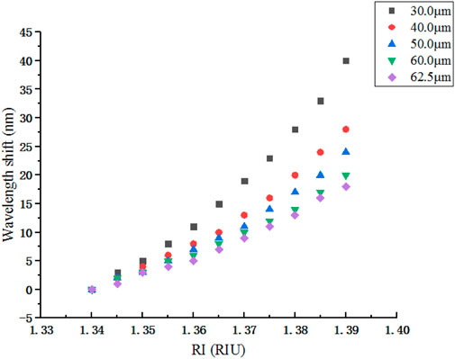
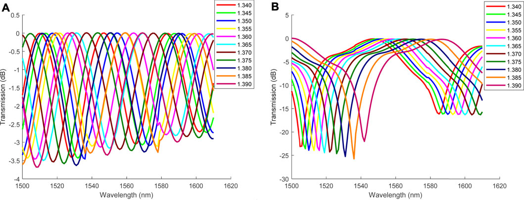
Figure 3 shows the effect of Dcore on RI sensitivity when the L1 value is 15 mm. Since the adjacent optimized diameter value varies greatly, it is difficult to find the same interference peak in a fixed waveband, but the general trend is the same, that is, the wavelength red shifts when RI increases, and RI sensitivity increases when Dcore decreases. However, it is not that the smaller the Dcore, the better will be the result. In the transmission spectrum of L1 shown in Figure 4, the smaller the diameter, the higher will be the overlap ratio of different interference peaks, then it is difficult to distinguish different peaks. Therefore, D1 is determined to be 30 μm according to Figure 4.
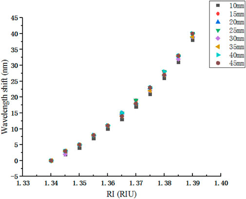
After preliminary parameter optimization, D1 is obtained and then the effect of length on RI sensitivity is roughly analyzed. Figure 5 shows wavelength shifts of interference peaks with different lengths at D1. It is worth noting that only appropriate but not the same interference peak is selected due to the large variation of length. The result indicated that the length has little effect on RI sensitivity when a diameter of NCF is relatively large. Then, in the next simulation process, we do not need to pay more attention to long length, just a few self-imaging periods is enough. Meanwhile, it proves that L1 is an appropriate value in the previous simulation. This is the first rough geometric parameter optimization process of NCF in SNS structure, and then L1 and D1 are finally optimized to be 15 mm and 30 μm.
NCF Second Precisely Parameter Optimization Process
D1 is set to be a constant, the length L2 is yet to be optimized to make SNS structure achieve a higher RI sensitivity. The normalized power at D1 is shown in Figure 2B, and then a multiple of self-imaging period and its adjacent values are selected to analyze the effect of NCF length on RI sensitivity, as shown in Figure 6A. Since there are many scattered points overlap in Figures 6A,B is the numerical refinement of partial RI range and linear fitting of RI sensitivity.
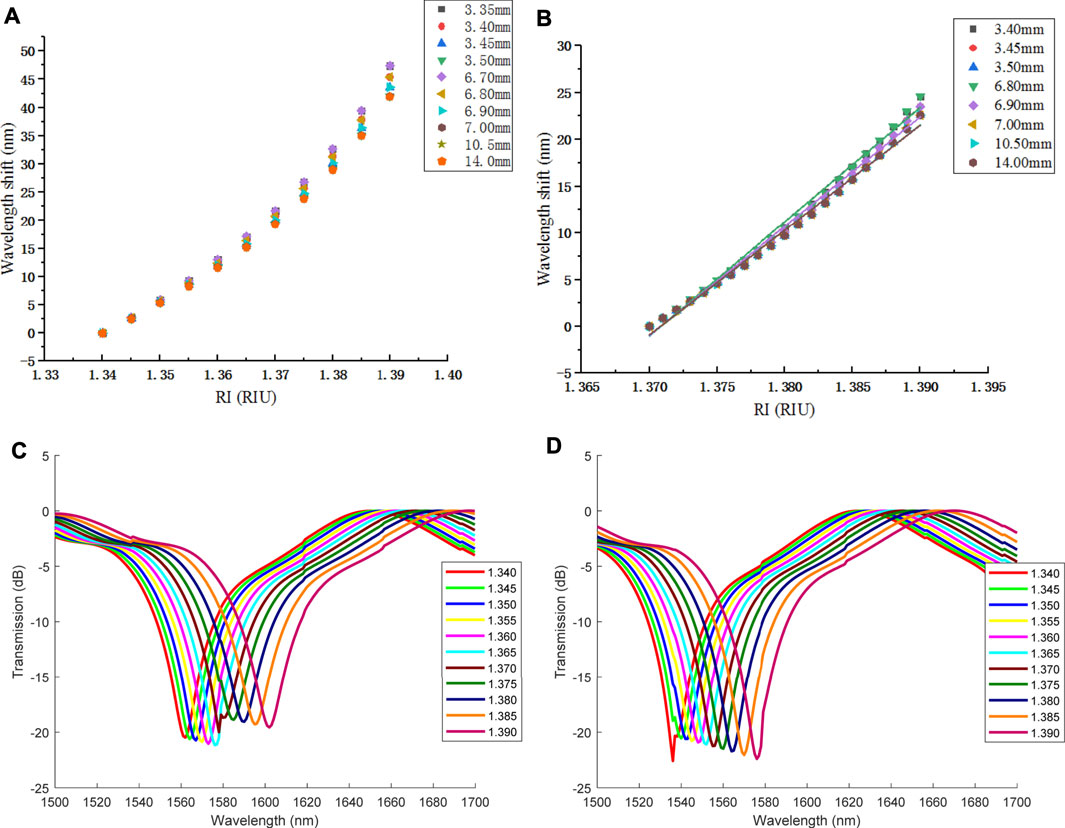
FIGURE 6. RI sensitivity of self-imaging length variation when D1 = 30 μm: (A) wavelength shift; (B) linear fitting; (C) transmission spectrum of 6.70 mm; (D) transmission spectrum of 6.80 mm.
Figure 6A shows that RI sensitivity corresponding to L of 3.35 and 6.70 mm is basically the same and relatively high, but the interference peak is approximately 1,700 nm when L is 6.70 mm in Figure 6C, which is not in an ideal waveband. For small diameter, the shorter the length, the more difficult will be to find a suitable interference peak for monitoring. Therefore, 3.35 mm is abandoned and it is considered that the length should not be too short.
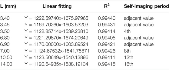
In Figure 6B and Table 1 formed by linear fitting of scattered points, RI sensitivity obtained by taking the 4th, 8th, 12th, and 16th self-imaging period as L is basically identical, which is also applicable to the adjacent length of the 4th self-image period and the 8th. Therefore, SNS structures with the same normalized power value in Figure 2 have approximately consistent RI sensitivity. Although RI sensitivity of 3.40 mm is slightly higher than that of 6.80 mm, as mentioned before, the short length of 3.40 mm is abandoned in favor of 6.80 mm. Then, as shown in Figure 6D, L2 of 6.80 mm is not a multiple of self-imaging period but an adjacent value.
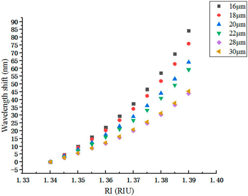
Then L2 is set to be a constant, and D2, which is smaller than D1, is yet to be optimized to obtain higher RI sensitivity of SNS structure. Because the smaller the NCF diameter, the more overlap occurs in the transmission spectrum. Therefore, during the re-optimization of Dcore, 16 μm is selected as the minimum optical diameter of NCF. Figure 7 shows that 16 μm can achieve higher RI sensitivity.
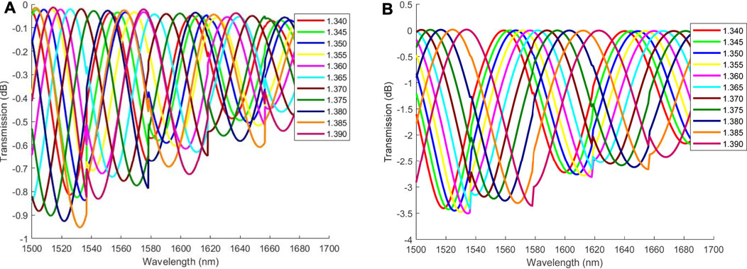
However, in Figure 8A, there is still so much overlap that it is not easy to distinguish a complete interference peak when Dcore is 16 μm. And the same as 18 μm, then D2 is optimized to be 20 μm according to Figure 8B.
D2 is set to be a constant, and the appropriate length L3 is yet to be optimized by calculating the self-imaging period corresponding to D2 using Eq. 2. The length of the 18th self-imaging period is approximately 6.70 mm, which is close to L2, so 6.70 mm is taken as the reference value for length optimization. In Figure 9A, adjacent lengths are also selected to find out the optimal length L3 with higher RI sensitivity.
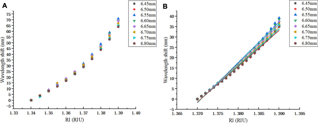
FIGURE 9. RI sensitivity of L variation at 1,500–1,700 nm when D2 = 20 μm: (A) wavelength shift; (B) linear fitting.
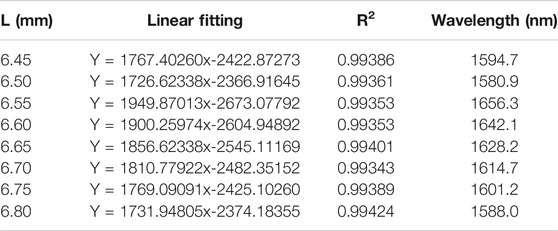
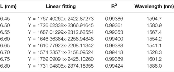
When RI is in the range of 1.340–1.370, it can be seen from Figure 9A that the change in length has little effect on RI sensitivity. So, only the RI range of 1.370–1.390 is analyzed specifically in Figure 9B. Meanwhile, the wavelength values of interference peaks corresponding to RI of 1.370 are marked in Table 2 obtained by linear fitting the data in Figure 9B. From Table 2, RI sensitivity is higher with L3 of 6.55 mm.
Effects of Waveband
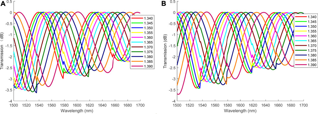
Sometimes, as shown in Figure 10A, the transmission spectrum contains more than one interference peak in the waveband of 1,500–1,700 nm. Figure 9A shows the wavelength monitoring results of the interference peak with better RI sensitivity corresponding to each length. Therefore, the next step is to analyze the effect of waveband on RI sensitivity.
If the waveband is selected as 1,550–1,700 nm, only the five lengths of 6.55, 6.60, 6.65, 6.70, and 6.75 mm in Figure 9A can be used for complete RI monitoring, and RI sensitivity corresponding to L3 of 6.55 mm is higher. If the waveband is 1,500–1,650 nm, RI sensitivity is shown in Figure 11A. Similarly, the RI range of 1.370–1.390 is analyzed in Figure 11B.
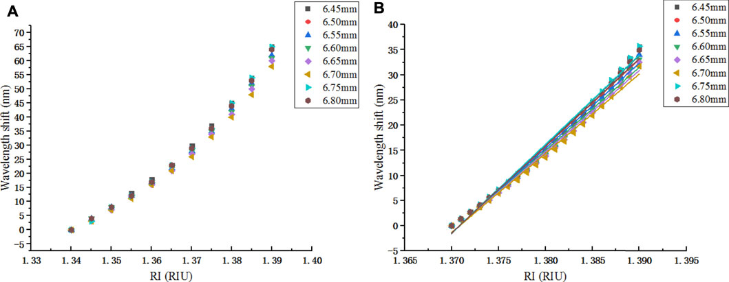
FIGURE 11. RI sensitivity of L variation at 1,500–1,650 nm when D2 = 20 μm: (A) wavelength shift; (B) linear fitting.
Table 3 obtained by Figure 11B indicates that RI sensitivity is relatively higher when L4 of NCF is 6.75 mm. The wavelength values with RI of 1.370 are marked in Table 3.
Tables 2, 3 show that different wavebands limit the appearance of different interference peaks, thus affecting RI sensitivity of different lengths. In order to analyze the reason of higher RI sensitivity when the length of NCF is a certain value, the RI is set to 1.370 and wavelength is fixed to 1,656.3 and 1,601.2 nm, the self-imaging phenomenon is shown in Figures 12A,B, L3 of 6.55 mm in Table 2, and L4 of 6.75 mm in Table 3 are at the maximum normalized power in Figures 12A,B, so they are also consistent with the previous statement that length is related to the self-imaging period.
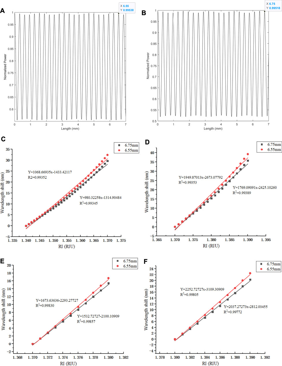
FIGURE 12. Comparison of NCF normalized power and RI sensitivity at L3 and L4: (A) NCF normalized power of L3; (B) NCF normalized power of L4; (C) comparison of RI sensitivity at 1.340–1.370; (D) comparison of RI sensitivity 1.370–1.390; (E) comparison of RI sensitivity 1.370–1.380; (F) comparison of RI sensitivity 1.380–1.390.
By comparing and analyzing L3 and L4 in Figures 12C,D, the results can be obtained that the RI sensitivity of L3 and L4 is approximately 1,068.7 and 980.3 nm/RIU when the RI range is 1.340–1.370, approximately 1949.9 and 1769.1 nm/RIU at 1.370–1.390. Because the higher the surrounding RI, the greater is the effect on RI sensitivity. Therefore, the scattered points in Figure 12D are fitted linearly again in Figures 12E,F.
RI varies from 1.380 to 1.390 and then RI sensitivity is approximately 2,252.7 nm/RIU when waveband is 1,550–1,700 nm and L3 is 6.55 mm. Similarly, the RI sensitivity is approximately 2037.3 nm/RIU when waveband is 1,500–1,650 nm and L4 is 6.75 mm. The resolution is 4.4 × 10⁻⁵ and 4.9 × 10⁻⁵, respectively. This is the whole process of NCF’ parameter optimization to obtain higher RI sensitivity.
SMF Parameter Optimization Process
After NCF optimization is completed, SMF parameter optimization is carried out. According to the guide mode cutoff condition in Eq. 3, in order to ensure that there is only one mode that exists in SMF, it is necessary to make the normalized frequency V < 2.405.
Because the core diameter is generally between 8 and 10 μm and simulation is based on Corning SMF-28e, then the diameter varies from 8.20 to 9.00 μm when SMF is optimized. NA indicates coupling efficiency which is related to
Conclusion
The geometric parameters of NCF are continuously optimized to obtain higher RI sensitivity. The final diameter of NCF is 20 μm when the RI range is 1.340–1.370 and 1.370–1.390, and RI sensitivity is approximately 1,068.7 and 1948.9 nm/RIU with the length of 6.55 mm, approximately 980.3 and 1769.1 nm/RIU with the length of 6.75 mm. Meanwhile, RI sensitivity can reach approximately 2,252.7 and 2037.3 nm/RIU when RI varies from 1.380 to 1.390, respectively. Although parameters of SMF are also considered to be optimized, the result shows that the effect on improving RI sensitivity of SNS structure can be ignored.
The structure optimization method proposed in this article can provide a reference for the optimal design of other mode interference structures. And SNS structure can have a great application prospect in monitoring battery expansion, especially when the surrounding RI is high.
Data Availability Statement
The original contributions presented in the study are included in the article/Supplementary Material; further inquiries can be directed to the corresponding author.
Author Contributions
SX conceived the project. SX and ZW contributed to the analysis of the data. ZW, HY, and SJ performed the computations and wrote the article with support from JL and ZS. HY and SJ reviewed the article. All authors contributed to the scientific discussion and article revisions.
Funding
This work was supported by the Youth Science Found Project of National Natural Science Foundation of China (NSFC) (61703090), Enterprise Postdoctoral Innovation Project Foundation of Tianjin City No. 2016; CNPC Bohai Drilling Engineering Company Project of Long-term Fiber Sensor Monitoring for Gas Storage under Grant No. CS201607K.
Conflict of Interest
The authors declare that the research was conducted in the absence of any commercial or financial relationships that could be construed as a potential conflict of interest.
Publisher’s Note
All claims expressed in this article are solely those of the authors and do not necessarily represent those of their affiliated organizations, or those of the publisher, the editors, and the reviewers. Any product that may be evaluated in this article, or claim that may be made by its manufacturer, is not guaranteed or endorsed by the publisher.
Acknowledgments
The authors thank all the staff of the Advanced Sensor Research Institute of Northeast Electric Power University for their help in carrying out this work.
References
An, J., Jin, Y., Sun, M., and Dong, X. (2014). Relative Humidity Sensor Based on SMS Fiber Structure with Two Waist-Enlarged Tapers. IEEE Sensors J. 14 (8), 2683–2686. doi:10.1109/JSEN.2014.2313878
Chen, Y., Wang, Y., Chen, R., Yang, W., Liu, H., Liu, T., et al. (2016). A Hybrid Multimode Interference Structure-Based Refractive index and Temperature Fiber Sensor. IEEE Sensors J. 16 (2), 331–335. doi:10.1109/JSEN.2015.2484346
Feng, X., Ouyang, M., Liu, X., Lu, L., Xia, Y., and He, X. (2018). Thermal Runaway Mechanism of Lithium Ion Battery for Electric Vehicles: a Review. Energ. Storage Mater. 10, 246–267. doi:10.1016/j.ensm.2017.05.013
Han, W., Tong, Z., and Cao, Y. (2014). Simultaneous Measurement of Temperature and Liquid Level Base on Core-Offset Singlemode-Multimode-Singlemode Interferometer. Opt. Commun. 321, 134–137. doi:10.1016/j.optcom.2013.12.078
Li, B., Jiang, L., Wang, S., Mengmeng Wang, Q. C., and Yang, J. (2012). A New Mach-Zehnder Interferometer in a Thinned-Cladding Fiber Fabricated by Electric Arc for High Sensitivity Refractive index Sensing. Opt. Lasers Eng. 50 (6), 829–832. doi:10.1016/j.optlaseng.2012.01.024
Li, E., Wang, X., and Zhang, C. (2006). Fiber-optic Temperature Sensor Based on Interference of Selective Higher-Order Modes. Appl. Phys. Lett. 89 (9), 091119. doi:10.1063/1.2344835
Liang, H. B., Du, J. H., Hao, X., Yang, S. Z., Tu, R., and Zhang, R. C. (2021). A Review of Current Research on the Formation Mechanism of Lithium Batteries. Energ. Storage Sci. Technol. 10 (1), 647–657. doi:10.19799/j.cnki.2095-4239.2020.0358
Liao, Z., Zhang, S., Zhao, Y., Qiu, Z., Li, K., Han, D., et al. (2020). Experimental Evaluation of Thermolysis-Driven Gas Emissions from LiPF6-Carbonate Electrolyte Used in Lithium-Ion Batteries. J. Energ. Chem. 49, 124–135. doi:10.1016/j.jechem.2020.01.030
Ma, L., Qi, Y., Kang, Z., and Jian, S. (2014). All-Fiber Strain and Curvature Sensor Based on No-Core Fiber. IEEE Sensors J. 14 (5), 1514–1517. doi:10.1109/JSEN.2014.2298553
Maleki, H., and Howard, J. N. (2006). Effects of Overdischarge on Performance and thermal Stability of a Li-Ion Cell. J. Power Sourc. 160 (2), 1395–1402. doi:10.1016/j.jpowsour.2006.03.043
Malitson, I. H. (1965). Interspecimen Comparison of the Refractive Index of Fused Silica*,†. J. Opt. Soc. Am. 55, 1205–1208. doi:10.1364/JOSA.55.001205
May-Arrioja, D. A., Ruiz-Perez, V. I., Bustos-Terrones, Y., and Basurto-Pensado, M. A. (2016). Fiber Optic Pressure Sensor Using a Conformal Polymer on Multimode Interference Device. IEEE Sensors J. 16 (7), 1956–1961. doi:10.1109/JSEN.2015.2510360
Shin, J.-S., Han, C.-H., Jung, U.-H., Lee, S.-I., Kim, H.-J., and Kim, K. (2002). Effect of Li2CO3 Additive on Gas Generation in Lithium-Ion Batteries. J. Power Sourc. 109 (1), 47–52. doi:10.1016/S0378-7753(02)00039-3
Su, J., Tong, Z., Cao, Y., and Zhang, W. (2014). High Sensitivity Multimode-Multimode-Multimode Structure Fiber Sensor Based on Modal Interference. Opt. Commun. 315, 112–115. doi:10.1016/j.optcom.2013.10.050
Tan, Y. C., Lou, J., Xu, H. M., Huang, J., Shen, W. M., and Li, B. C. (2013). Simulation and Analysis of Sensitivity for Optical Fiber Evanescent Wave Absorbing Sensors. Yadian Yu Shengguang/Piezoelectrics and Acoustooptics. 35 (6), 810–813.
Tripathi, S. M., Kumar, A., Varshney, R. K., Kumar, Y. B. P., Marin, E., and Meunier, J.-P. (2009). Strain and Temperature Sensing Characteristics of Single-Mode-Multimode-Single-Mode Structures. J. Lightwave Technol. 27 (13), 2348–2356. doi:10.1109/JLT.2008.2008820
Wang, H. W., Deng, S., Xiao, H. Q., Zhao, H. F., and Wang, C. (2014). Research of Overcharge/overdischarge of Power Li-Ion Battery under Different Ambient Temperatures. Chin. J. Power Sourc. 38 (03), 431–433.
Wang, Q., Li, C., Zhao, C., and Li, W. (2016). Guided-Mode-Leaky-Mode-Guided-Mode Fiber Interferometer and its High Sensitivity Refractive Index Sensing Technology. Sensors 16, 801. doi:10.3390/s16060801
Wu, Q., Semenova, Y., Wang, P., and Farrell, G. (2011). High Sensitivity SMS Fiber Structure Based Refractometer - Analysis and experiment. Opt. Express 19 (9), 7937–7944. doi:10.1364/OE.19.007937
Wu, Y., Deng, X., Li, F., and Zhuang, X. (2007). Less-mode Optic Fiber Evanescent Wave Absorbing Sensor: Parameter Design for High Sensitivity Liquid Detection. Sensors Actuators B: Chem. 122 (1), 127–133. doi:10.1016/j.snb.2006.05.026
Yan, S., Deng, J., Bae, C., and Xiao, X. (2018). Thermal Expansion/shrinkage Measurement of Battery Separators Using a Dynamic Mechanical Analyzer. Polym. Test. 71, 65–71. doi:10.1016/j.polymertesting.2018.08.028
Zhang, S., Wang, Z., Zhu, M., Li, L., Wang, S., Li, S., et al. (2020). A Compact Refractive index Sensor with High Sensitivity Based on Multimode Interference. Sensors Actuators A: Phys. 315, 112360. doi:10.1016/j.sna.2020.112360
Zhang, Y., Tian, X., Xue, L., Zhang, Q., Yang, L., and Zhu, B. (2013). Super-High Sensitivity of Fiber Temperature Sensor Based on Leaky-Mode Bent SMS Structure. IEEE Photon. Technol. Lett. 25 (6), 560–563. doi:10.1109/LPT.2013.2245644
Zhao, Y., Cai, L., and Hu, H.-F. (2015). Fiber-Optic Refractive Index Sensor Based on Multi-Tapered SMS Fiber Structure. IEEE Sensors J. 15, 6348–6353. doi:10.1109/JSEN.2015.245889311
Zhao, Y., Cai, L., Li, X.-G., Meng, F.-c., and Zhao, Z. (2014). Investigation of the High Sensitivity RI Sensor Based on SMS Fiber Structure. Sensors Actuators A: Phys. 205, 186–190. doi:10.1016/j.sna.2013.10.023
Zhou, D.-P., Wei, L., Liu, W.-K., Liu, Y., and Lit, J. W. Y. (2008). Simultaneous Measurement for Strain and Temperature Using Fiber Bragg Gratings and Multimode Fibers. Appl. Opt. 47 (10), 1668–1672. doi:10.1364/AO.47.001668
Zhou, G., Wu, Q., Kumar, R., Ng, W. P., Liu, H., Niu, L., et al. (2017). High Sensitivity Refractometer Based on Reflective Smf-Small Diameter No Core Fiber Structure. Sensors 17, 1415. doi:10.3390/s17061415
Keywords: battery expansion monitoring, refractive index sensitivity, parameter optimization, SNS, waveband
Citation: Xu S, Wang Z, Yang H, Jiao S, Liu J and Shang Z (2021) Optimization Design of SNS Sensor Structural Parameters for Battery Expansion Monitoring. Front. Energy Res. 9:725458. doi: 10.3389/fenrg.2021.725458
Received: 15 June 2021; Accepted: 09 August 2021;
Published: 24 September 2021.
Edited by:
Jonghyun Park, Missouri University of Science and Technology, United StatesCopyright © 2021 Xu, Wang, Yang, Jiao, Liu and Shang. This is an open-access article distributed under the terms of the Creative Commons Attribution License (CC BY). The use, distribution or reproduction in other forums is permitted, provided the original author(s) and the copyright owner(s) are credited and that the original publication in this journal is cited, in accordance with accepted academic practice. No use, distribution or reproduction is permitted which does not comply with these terms.
*Correspondence: Shibo Xu, MjAxODI3ODFAbmVlcHUuZWR1LmNu
 Shibo Xu
 Zhe Wang
 Hanrui Yang
 Shengxi Jiao