 Yang Chen
 Han Wang
 Miao Zhu
95% of researchers rate our articles as excellent or good
Learn more about the work of our research integrity team to safeguard the quality of each article we publish.
Find out more
ORIGINAL RESEARCH article
Front. Energy Res. , 27 July 2021
Sec. Smart Grids
Volume 9 - 2021 | https://doi.org/10.3389/fenrg.2021.712397
This article is part of the Research Topic Advanced Technologies for Modeling, Optimization and Control of the Future Distribution Grid View all 11 articles
Modular multilevel converter based unified power flow controller (MMC-UPFC) can provide flexible power regulation and plays an important role in the smart grid and future distribution networks. PI controller is widely adopted in the Unified power flow controller (UPFC) control. However, it is often difficult to figure out a pair of stable control parameters with good dynamic performance. A passive sliding mode control strategy of MMC-UPFC is proposed in this paper to achieve the advantages of both the passive controller and sliding mode controller. The proposed passive sliding mode control strategy has a fast response speed and is not sensitive to system parameter variation. Since unbalance grid voltage conditions are common in the modern distribution networks, an unbalanced grid treatment strategy is also presented with the series side of MMC-UPFC. Negative sequence components of the grid voltages are detected by the cross-decoupling method with second order generalized integrator and then compensated by the series side of MMC-UPFC. The series side converter controls the power flow and treats unbalanced grid conditions simultaneously. The efficiency of the general device is increased thus. A 27-level MMC-UPFC simulation system is built based on the Shanghai UPFC Project and validate the proposed approach.
Modern flexible AC transmission systems (FACTS) devices are the key components in the smart grid and the future energy internet. FACTS devices leverage the potential of the power grid and enable the smarter power grid in the future energy network (Peng, 2017). Unified power flow controller (UPFC) is one of the most powerful power conditioners in the FACTS device family (Gyugyi et al., 1995).
A typical UPFC often consists of two back-to-back connected shunt- and series-connected AC-DC converters. Transmission line power flow can be controlled by the series side converter and the inner DC bus voltage can be regulated by the shunt side. Due to the development of modular multilevel converter (MMC) technologies (Akagi, 2017; Haque et al., 2020), UPFC has enjoyed a new research and construction boom in recent years. Several MMC-UPFC projects have been put into operation in China recently. The UPFC for 220 kV Nanjing Western-Ring Grid launched in 2015 is the first MMC-UPFC in the world (Li, et al., 2016). The first urban MMC-UPFC is launched for Shanghai distribution network in 2017. The 500 kV UPFC in southern Jiangsu Province is playing an important role in the power flow regulation of Suzhou grid.
Classical dual-loop control strategy can be applied to the cascaded AC-DC converters in the UPFC. PI controllers are widely used in the dual-loop control, which can achieve good steady-state performances with certain parameters. However, there may be steady state error and the dynamic performance will be affected when system parameters change. To improve the dynamic response, nonlinear control strategies such as model predictive control (MPC) (Guo et al., 2018; Ramirez et al., 2020), passive control (Yang, et al., 2018), and sliding mode control (SMC) (Yang et al., 2019; Feng et al., 2020) are proposed for MMC-UPFC. However, MPC requires precise system modeling and the computation amount increases with the increased number of switches in the converter. Passive control is another non-linear control strategy from the system energy attributes which provides a faster step response and better transient dynamics due to the injected extra system damping. A passive control scheme for multi-terminal VSC-HVDC is investigated in (Yang et al., 2018), which can achieve a reliable and effective renewable energy integration. However, passive control requires precise system modeling. Thus the wider application of passive control is limited significantly. SMC is an efficient tool to design robust controllers which has been widely used in the converter controller designing (Ma et al., 2019; Feng et al., 2020). An observer based sliding mode frequency control strategy is proposed for multi-machine power systems with high renewable energy (Tummala et al., 2018). A fractional-order sliding mode control is proposed for a D-STATCOM to compensate the low power distribution system (Ahmed et al., 2021). An adaptive sliding mode reactive power control strategy is proposed in (Mi et al., 2019) to eliminate system parameter uncertainties or disturbances and improve the system stability. The integration of passive control and sliding mode control is proved to be an efficient approach for MMC-UPFC control (Ke et al., 2019). The inherent chattering problem can be solved by adopting integral sliding surface.
On the other side, the unbalanced grid condition is one of the most severe power quality issues. Shunt connected FACTS devices often deal with power quality problems by inserting currents to the bus. Several research works have been done on power quality treatment with shunt side converters of UPFC as well. However, there was rare work on the series side compensation. Meanwhile, plenty of researches have been done on VSC and MMC operation under unbalanced grid conditions (Li et al., 2018; Shang et al., 2019; Kryonidis et al., 2021). The multiple objective control method (Stefanov and Stankovic, 2002), modeling and operation analysis of UPFC with unbalanced conditions (Yang et al., 2020), the methods of the fault ride improvement of MMC-UPFC (Santos et al., 2014) have been discussed widely. An arm current balancing control and capacitor voltage reduction method for MMC-UPFC under unbalanced grid conditions are proposed in (Li et al., 2019) and (Wang et al., 2019) respectively. The controllable regions of MMC-UPFC under unbalanced grid conditions are investigated and a voltage limit control is given accordingly in (Hao et al., 2017). The influence of UPFC in grid fault scenarios are analyzed in (Akter et al., 2020) and (Chatterjee and Sudipta, 2020). As mentioned above, most researches focused on the operation of UPFC under unbalanced grid voltage conditions. As the most powerful FACTS device, both sides of UPFC can take part in the treatment of unbalanced grid conditions as well.
To improve the performance of MMC-UPFC, a passive sliding mode control (P-SMC) strategy is proposed and discussed firstly in this paper. The dependence of passive control on precise modeling is overcome by the adoption of sliding mode control. The integral sliding mode is introduced to solve the chattering problem of the classical sliding mode control. The proposed passive sliding mode control strategy is easy to implement with fast response.
The treatment strategy for unbalanced grid conditions is provided using the series side of MMC-UPFC afterwards. The negative sequence components of the grid currents are detected via the cross-decoupling strategy with second order generalized integrator. The negative sequence voltages are inserted by the series side of MMC-UPFC to compensate the grid negative sequence voltage. The grid currents return to symmetry and the power quality can be improved.
Mathematical modeling, theoretical analysis, and simulation results of a 27 level MMC-UPFC system are provided in the paper and validate the proposed P-SMC strategy and unbalanced condition treatment strategy.
MMC-UPFCs usually contain two back-to-back MMC-structured converters. A Typical layout of MMC-UPFC in the power grid is shown in Figure 1.
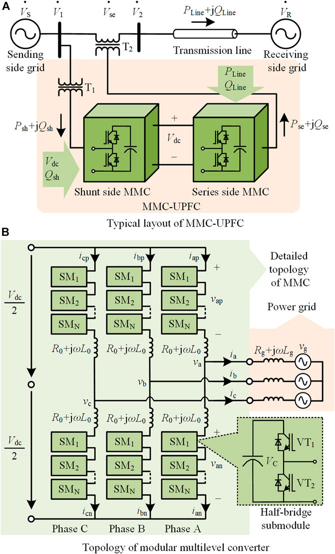
FIGURE 1. Typical topology and application of MMC-UPFC in power grid.
The shunt side MMC of UPFC obtains power from the bus to keep the DC link voltage Vdc constant and injects reactive power to the AC bus. The series side MMC employs a voltage source vse series connected in the transmission line. By changing the amplitude and phase angle of the inserted series voltage vse, active and reactive power through the transmission line can be controlled. The series side MMC performs like the Static Synchronous Series Compensator (SSSC) but has higher flexibility due to the stable DC link voltage provided by the shunt side MMC.
As shown in Figure 1, both shunt and series sides of the MMC-UPFC share the same modular multilevel converter topology. Thus the Euler-Lagrange model of the general MMC is deduced in this part for the further controller design in the next section. The equivalent circuit of MMC is provided in Figure 2. The mathematic model of the grid connected MMC can be expressed as Eq. 1.
Here in Eq. 1, j = a, b, c. The dynamic model of MMC with differential- and common-mode components in the static abc frame can be deduced as follows from Eq. 1.
The differential- and common-mode voltages and currents mentioned in Eq. 2 are defined as follows.
Here in Eq. 3 and Eq. 4, vjn and vjp are composed of submodule capacitor voltages and they are adjusted by changing submodule states. The differential voltage component vjdiff is equivalent to the output AC voltage v of MMC. Thus vjdiff is replaced by v in the following modeling. R0/2 + jωL0/2 is equivalent to the cascaded impedance of MMC. The equivalent grid impedance Rg + jωLg and the equivalent converter impedance R0/2 + jωL0/2 are replaced by a general impedance R + jωL in the following modeling as well.
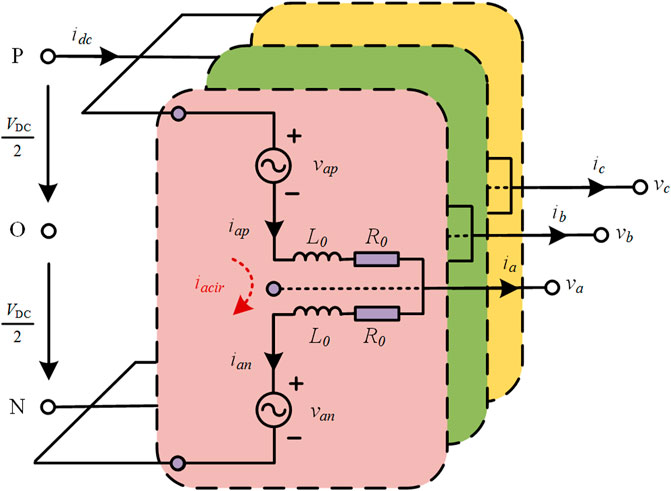
FIGURE 2. Equivalent circuit of MMC.
When the unbalanced grid condition occurs in the power grid, the grid voltage and current can be separated into positive, negative, and zero sequence components by the symmetrical components method. The zero sequence current can be eliminated by setting proper transformer winding connection mode in the high voltage transmission system. The unbalanced grid condition treatment strategy is another topic of this paper. Thus the control of positive and negative components are the focus of this paper. The positive and negative sequence EL model of MMC are deduced in the remaining of this section.
The universal positive and negative sequence models of MMC in dq frames are shown in Eq. 5 and Eq. 6.
According to Eq. 5 and Eq. 6, MMC has the same output model with traditional three-phase inverters. Thus, the classical decoupled dual-loop control can be applied for MMC control as well.
The positive and negative sequence models of MMC in Eq. 5 and Eq. 6 can be rewritten in the form of Euler-Lagrange (EL) model as shown in Eq. 7 and Eq. 8.
The meanings and basic features of each matrix in Eq. 7 and Eq. 8 are explained as follows:
• x+ and x- are the state variable of the system.
• u+and u- are the energy exchanges between the system and the external environment.
• M is the positive definite diagonal matrix.
• J+ and J− are the antisymmetric matrix of the positive and negative sequence system respectively. The two matrixes satisfy J+=−J+T and J−= −J−T with consideration of the interconnection structure of the system.
• R is the positive definite matrix which represents the dissipative characteristics of the system.
Note that the shunt and series sides of the MMC-UPFC in Figure 1 share the same mathematical model form since they have the same MMC topology. Then the passive sliding mode control will be proposed in the following section on the basis of the EL models here.
The passive sliding mode control is proposed in the inner current loop of both the shunt and series sides of the MMC-UPFC instead of the traditional PI controller, which provides easier parameter design and better dynamic performance for the proposed MMC-UPFC. The design of the passive sliding mode control strategy of the MMC positive sequence system is discussed in this section.
The passive control redistributes the energy of the system and injects nonlinear damping to the system. It can help the system energy track the pre-set energy function and make the state variable of the system gradually converges to the set value. Then the system can finally reach the specified control target. Here the positive sequence system of MMC is taken to show the whole controller design process.
When the grid voltage is unbalanced, the expected stable balance point of the positive sequence system is Eq. 14.
Here in Eq. 14, i + dref is the expected stable value of the state variable i + d, which is the d frame component current and it controls the output active power. i + qref is the expected stable value of the state variable i + q, which is the q frame component current and it controls the output reactive power.
The error component of the MMC positive sequence system is Eq. 15.
The EL error model of the MMC positive sequence system can be obtained as Eq. 16 from the EL mathematical model of MMC given in Eq. 7.
The damping injection method is applied to accelerate the energy dissipation of the system and make the system converge to the expected point faster. Thus, the system conversion can quickly reach the expected point. The new damping dissipation term is Eq. 17 with the newly added positive definite matrix of injected damping R+ a.
Here in Eq. 17, the newly injected damping R+ a is Eq. 18.
In order to realize the decoupling control, the original EL error model Eq. 7 is rewritten. The new EL error model of the MMC positive sequence system with the newly injected damping R+ a is Eq. 19.
If Q+ is 0, the steady-state error will be eliminated and the decoupling control can be achieved. Thus the passive control law of the positive sequence system is selected as Eq. 20.
Thus the passive controller of the MMC positive sequence system in dq frame can be derived as follows.
The stability of the passive controller can be proved by the Lyapunov stability theory. The energy function of the MMC positive sequence system V+ is selected as Eq. 22. Due to the positive definiteness of matrix M, V+ is always positive.
The derivative of the above energy function V+ can be calculated by Eq. 23.
Since the terminal value of Q+ is 0, the derivative of V+ is Eq. 24 and it is obviously negative.
The conclusion can be drawn that V+ is always positive while the derivative of V+ is negative. The system is proved to be asymptotically stable according the Lyapunov stability theory.
The passive control theory requires precise system parameters to achieve higher dynamic performance. However, several system parameters cannot be measured directly and precisely. There may be parameter perturbation during the long operating process as well. System parameters will change when the grid operation mode changes. These will lead to the change of the system balancing point in the passive controller above.
The sliding mode control has good performance facing system parameter variation. Therefore, the sliding mode control is integrated in the proposed passive controller to acquire the advantages of the two control strategies.
It is known that there is often a steady-state error in the linear sliding mode control of MMC-UPFC. An integrator is introduced in the control loop to eliminate the steady state error of sliding mode control. The positive sequence system sliding surfaces s + dand s + q in the dq frame are selected as Eq. 25.
Here in Eq. 25, k+pd, k+id, k+pq, and k+iq are the control parameters of the sliding faces. The ubiquitous high frequency chattering problem of traditional sliding mode control can be solved by choosing the exponential reaching law with saturated function sat (·) instead of the ideal symbolic function sgn (·). The proposed exponential reaching law is presented in Eq. 26.
Here in Eq. 26ε+d, ε+q, k +d, k+q are the reaching law parameters and they are all positive. This ensures the product of the sliding face s and its derivative
The saturated function sat (·) is shown in Eq. 27, which gives the system a boundary layer Δ. The exponential reaching law is applied outside the boundary layer. Thus the tracking error can be reduced fast. When it comes into the boundary layer, the linear approach law is applied to slow down the reaching speed and the chattering phenomenon can be reduced.
The general passive sliding mode controller of the positive sequence system can be derived as Eq. 28 by combining Eq. 21, Eq. 25, and Eq. 26.
The stability of the passive sliding mode controller can be proved by selecting as2 (a > 0) as the energy function according to the Lyapunov stability theory.
The passive sliding mode controllers mentioned above serve as the inner current loop in the dual-loop control strategy. The output power is controlled by the outer loop. Power calculation for output power control is shown as Eq. 29 in the grid voltage vector oriented dq frame.
Active and reactive power related controls are decoupled according to Eq. 29. The inner d component current id loop provides active power related control abilities. The inner q component current iq loop provides reactive power related control abilities. As shown in Figure 3, the main control target of the shunt side of MMC-UPFC contains two main parts. One is the DC voltage control which provides a stable DC bus voltage Vdc with id current loop while the other is the reactive power control with the iq current loop. They provide the AC voltage reference vjdiff together. Thus the reference values of each bridge arm vjpref and vjnref are calculated by Eq. 30 according to Eq. 3.
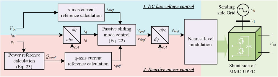
FIGURE 3. General control diagram of the shunt side of MMC-UPFC.
Unbalanced grid condition is a common power quality problem in the modern power system. The unbalanced grid phasors can be resolved into three sets of sequence components according to the method of symmetrical components. They are positive sequence components, negative sequence components, and zero sequence components. The zero sequence components in the power grid can be eliminated by choosing the proper transformer connection method. Thus, the negative sequence components are the main problem to be dealt with in the unbalanced condition treatment.
The shunt side of UPFC performs as a current source and it is suitable for unbalanced local load compensation which has been well discussed in the existing works. A typical UPFC consists of two back-to-back connected converters and the series side of UPFC can deal with the unbalanced condition in the power grid networks such as unbalanced grid voltage and unbalanced line impedance as well.
The general treatment strategy is to provide negative sequence voltages by the series side of MMC-UPFC and compensate the negative components of the grid voltage so that the transmission line current can return to symmetry. Thus, the negative component controller is needed besides the regular control discussed in the previous section.
A detailed control diagram of the series side is shown in Figure 4 with unbalanced grid treatment. As shown in the red part, the control diagram of the series side has an additional negative sequence control loop which provides unbalanced grid condition treatment besides the similar power control loop in Figure 3.
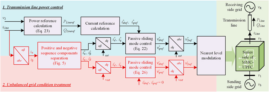
FIGURE 4. General control diagram of the series side of MMC-UPFC with unbalanced grid condition treatment strategy.
A cross-decoupling positive and negative components separation method is proposed with the second-order generalized integrator (SOGI) firstly as shown in Figure 5. The positive and negative sequence components can be separated precisely. The positive sequence components help to control the transmission line power while the negative sequence components are to be eliminated according to the unbalanced grid condition treatment strategy.
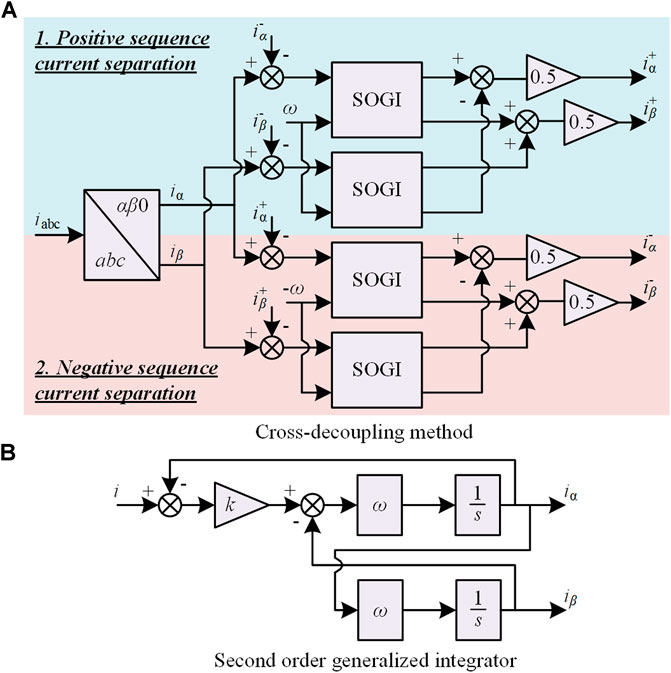
FIGURE 5. Positive and negative sequence separation method with SOGI.
According to the negative sequence mathematic model given in Eq. 8, the model of the negative sequence passive controller in the dq frame can be derived as Eq. 31.
Combining the sliding mode control strategy to improve the performance of system parameter variation, the passive sliding mode control law of the negative sequence system is deduced in Eq. 32.
The power flow through the transmission line is regulated by the series side of MMC-UPFC. The natural power flow without the inserted voltage by MMC-UPFC can be calculated by Eq. 33.
Here in Eq. 33, F1 (φR) and F2 (φR) are as follows.
After the MMC-UPFC is enabled, the new power flow can be calculated by Eq. 35.
Here in Eq. 35, H1 (φUPFC) and H2 (φUPFC) are as follows.
The power flow change with the inserted
Here in Eq. 37, T1 (φUPFC) and T2 (φUPFC) are as follows.
If the resistive component RLine is neglected, Eq. 37 can be simplified as Eq. 39.
The power calculation equations in Eq. 39 have similar structures to the power formulae of the high voltage power grid, but the variation of the active power and reactive power flow are not decoupled. This is because both VUPFC and φUPFC can be regulated widely and freely. The ideal power flow regulating range without an unbalanced grid treatment strategy is shown in Figure 6.
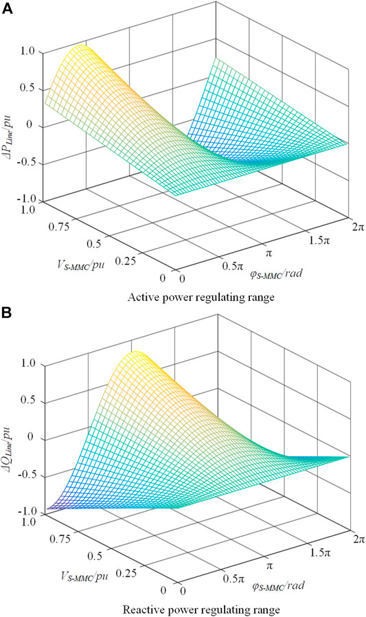
FIGURE 6. Ideal power flow regulating range in balanced power grid.
Due to the inserted negative sequence voltages for unbalanced grid compensation, the output voltages of the series side of MMC-UPFC are unbalanced as well. The general phasor diagram of UPFC with unbalanced grid condition treatment is shown in Figure 7.
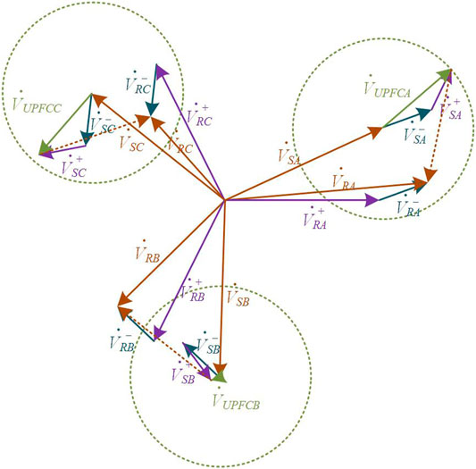
FIGURE 7. Phasor diagram of UPFC with unbalanced grid condition treatment.
Here in Figure 7, the brown solid lines are the sending and receiving side grid voltages VS and VR, respectively. The receiving side voltages VRA/B/C are unbalanced, and they can be solved to the positive and negative components of VRA/B/C, which are represented by purple and dark green arrows, respectively. The negative components bring unbalanced transmission line currents. The output voltages VUPFCA/B/C of MMC-UPFC are represented by light green arrows, and they can be solved to the positive and negative components as well. The negative components V—SA/B/C of UPFC compensate the receiving side negative sequence voltages V—RA/B/C. The positive components V+SA/B/C of UPFC provides active power flow control.
The insert voltage amplitude range of the MMC-UPFC is shown as the light green circle in Figure 7. The positive sequence voltage of UPFC cannot reach the boundary from the start point with the same amplitude freely as that in the balanced grid condition. Thus, the power flow regulating range is influenced by the negative sequence voltage. The additional voltage limit control in Figure 7 is necessary, and the power flow regulating range is narrowed down accordingly.
A 27-level MMC-UPFC simulation system, based on the recent UPFC project in Shanghai of China, is built in MATLAB/Simulink to verify the proposed control strategy. The main circuit is the same as Figure 1. The specific parameters of the system are shown in Table 1.
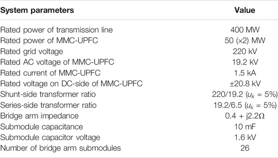
TABLE 1. Parameters of the simulation system.
The general power flow control performance of MMC-UPFC is given in this section firstly. Then the performance of unbalanced grid treatment is presented. Two scenarios are discussed separately. One is the unbalanced grid voltages while the other is the asymmetrical transmission lines. Simulation results verify the proposed control strategy and treatment strategy.
Simulation results of the steady and dynamic state performances of the proposed P-SMC strategy are presented in this part and then compared with the traditional PI controller to verify the performance improvement of the proposed control strategy.
According to the parameters given in Table 1, the initial power flow without UPFC is approximately 327 + j51MVA. During the time from 0.2 to 2 s, the active power and reactive power are set as different values. The power references at different times are provided in Table 2.

TABLE 2. Power references in different time period.
The performance of MMC-UPFC with the proposed passive sliding mode control strategy during power flow regulation is shown in Figure 8.
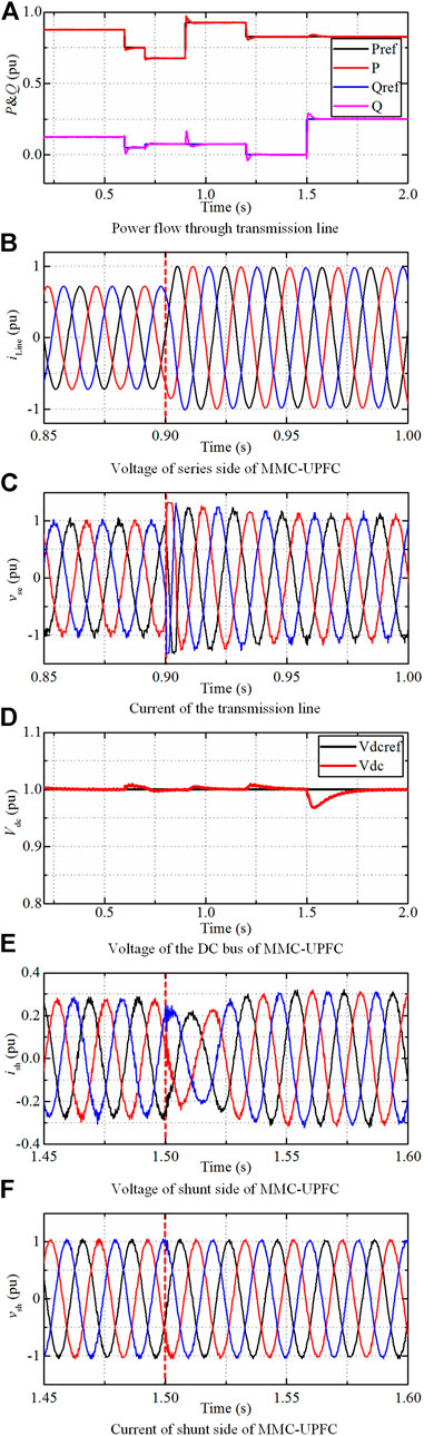
FIGURE 8. Simulation results of the proposed passive-sliding mode control strategy.
At the series side of MMC-UPFC: The output active and reactive power follow the power references well as shown in Figure 8A. The dynamic response at 0.9 s is provided in Figures 8B,C. The inserted voltages by the series side of MMC-UPFC respond to the change of power reference immediately as shown in Figure 8B. The transmission line current is changed accordingly in Figure 8C to regulate the transmission line power.
At the shunt side of MMC-UPFC: The dynamic response at 1.5 s is provided in Figures 8D–F. The voltage of the DC bus is maintained stable as shown in Figure 8D due to the shunt side of MMC-UPFC whose dynamic responses are provided in Figures 8E,F.
The power flow through the transmission line follows the reference values well due to the regulation by the series side of MMC-UPFC. The DC link voltage maintains stable due to the regulation by the shunt side of MMC-UPFC. The proposed passive sliding mode control strategy is validated by the simulation results.
In this scenario, the grid impedance fluctuation and control delay are considered disturbing items. The power flow control performances are presented. The same PI controllers are adopted in the outer power control loop while the inner current loops with PI controller and P-SMC controller are adopted respectively. Main control parameters are provided in Table 3.
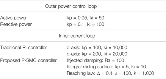
TABLE 3. Main control parameters.
The P and Q reference values are changed from 0.875/0.125 to 0.75/0.05 at 0.20 s. The performance comparison is provided in Figure 9. The meaning of each scenario are:
Scenario 1: 10−4s control delay and normal transmission line impedance. 1) PI control; 2) P-SMC.
Scenario 2: 2 × 10⁻⁴s control delay and 0.9 times as normal transmission line impedance. 1) PI control; 2) P-SMC.
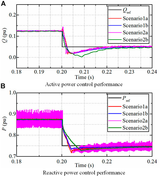
FIGURE 9. Treatment strategy performance under unbalanced grid voltage.
The control parameters are designed and optimized for scenario 1. As can be seen in Figure 9, the proposed P-SMC has similar dynamic performance with PI controller in scenario 1, and both control strategies have fast and precise dynamic performances. However, when the system parameters change in scenario 2, the P-SMC performance is still fast and precise while the PI control results are fluctuating with the same control parameters scenario 1 and 2.
The comparison results show that the proposed P-SMC provides fast and robust performances than traditional PI controllers when facing system disturbances.
Simulation results of MMC-UPFC under unbalanced grid voltage conditions and asymmetrical line conditions are presented in this part to verify the proposed treatment strategy.
In this scenario, the negative sequence voltages with the amplitude of 0.04 pu are added at the receiving side grid. The unbalanced grid treatment strategy is put into use at 0.5 s. The whole process of unbalanced condition treatment of MMC-UPFC is shown in Figure 10.
FIGURE 10. Treatment strategy performance under unbalanced grid voltage condition.
The transmission line current is asymmetrical before the unbalanced treatment strategy is enabled at 0.5 s. The negative sequence voltages are separated precisely by the proposed cross-decoupling method with SOGI. The negative sequence components of transmission line current are reduced to nearly zero as shown in Figure 10A. The unbalance factor of line currents is reduced from about 36 to 0.7% quickly. The terminal voltages of the transmission line in Figure 10C are asymmetrical from 0.5 s due to the inserted negative sequence voltage from the series side of MMC-UPFC. Simulation results in this scenario well validate the proposed unbalanced treatment strategy.
In this scenario, the transmission line between the sending side grid and the receiving side grid is set to be asymmetrical. The transmission line impedance of Phase A is 1.1 times that of Phase B and C. The whole process of unbalanced condition treatment of MMC-UPFC is shown in Figure 11.
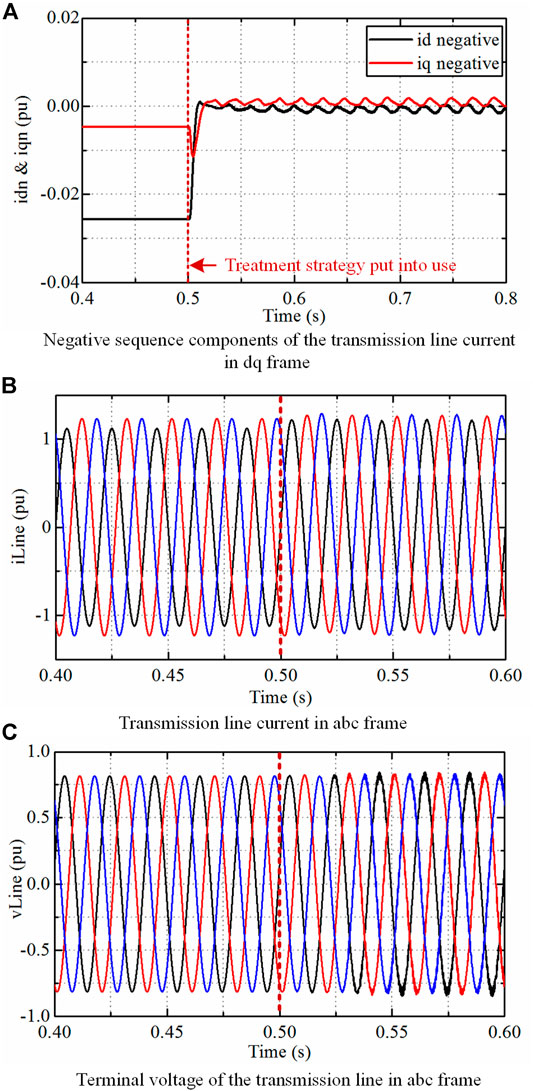
FIGURE 11. Treatment strategy performance under asymmetrical transmission line condition.
The transmission line current is asymmetrical before the unbalanced treatment strategy is enabled. The negative sequence voltages are separated precisely by the proposed cross-decoupling method with SOGI. The negative sequence components of transmission line current are reduced to nearly zero and the unbalance factor of currents is reduced from about 16 to 0.5% quickly. The terminal voltages of the transmission line are slightly asymmetrical from 0.5 s due to the inserted negative sequence voltage from the series side of MMC-UPFC. Simulation results in this scenario well validate the proposed unbalanced treatment strategy.
A passive sliding mode control strategy is proposed and discussed in this paper providing fast and precise control for MMC-UPFC. The unbalanced grid condition treatment strategy for distribution networks is then proposed with the series side of MMC-UPFC. The proposed approach is validated by simulation results based on a 27 level MMC-UPFC. Conclusions are drawn as below.
1) The detailed passive sliding mode controller of the MMC-UPFC design from the energy attributes system provides fast, precise, and robust transmission line power flow control and enables more control flexibility for the smart grid.
2) The proposed unbalanced grid condition treatment strategy with the series side of MMC-UPFC reduces line current unbalance factor and improves power quality effectively. The adoption of the series side of MMC-UPFC in the treatment strategy increases the efficiency of the whole device.
3) The deduced power flow regulating range changing due to the unbalanced grid treatment leads to the additional voltage limit control and enables the high operation quality of MMC-UPFC.
The original contributions presented in the study are included in the article/Supplementary Material, further inquiries can be directed to the corresponding author.
YC: analysis, modeling, method, verification and writing. HW and ML: conceptualization and methodology. JM: simulation and verification. MZ and XC: advising, supervision, writing-reviewing and editing.
This work was supported by the Program of Shanghai Academic Research Leader (19XD1422000).
The authors declare that the research was conducted in the absence of any commercial or financial relationships that could be construed as a potential conflict of interest.
All claims expressed in this article are solely those of the authors and do not necessarily represent those of their affiliated organizations, or those of the publisher, the editors and the reviewers. Any product that may be evaluated in this article, or claim that may be made by its manufacturer, is not guaranteed or endorsed by the publisher.
Ahmed, T., Waqar, A., Elavarasan, R. M., Imtiaz, J., Premkumar, M., and Subramaniam, U. (2021). Analysis of Fractional Order Sliding Mode Control in a D-STATCOM Integrated Power Distribution System. IEEE Access 9, 70337–70352. doi:10.1109/ACCESS.2021.3078608
Akagi, H. (2017). Multilevel Converters: Fundamental Circuits and Systems. Proc. IEEE 105 (11), 2048–2065. doi:10.1109/JPROC.2017.2682105
Akter, S., Biswal, S., Rathore, N. S., Das, P., and Abdelaziz, A. Y. (2020). Amplitude Based Directional Relaying Scheme for UPFC Compensated Line during Single Pole Tripping. Electric Power Syst. Res. 184, 106290. doi:10.1016/j.epsr.2020.106290
Chatterjee, B., and Debnath, S. (2020). Sequence Component Based Approach for Fault Discrimination and Fault Location Estimation in UPFC Compensated Transmission Line. Electric Power Syst. Res. 180, 106155. doi:10.1016/j.epsr.2019.106155
Feng, F., Yu, J., Dai, W., Yang, Z., Zhao, X., Kamel, S., et al. (2021). Operational Reliability Model of Hybrid MMC Considering Multiple Time Scales and Multi-State Submodule. J. Mod. Power Syst. Clean Energ. 9, 648–656. doi:10.35833/MPCE.2019.000227
Feng, X., Tao, Y., Cui, X., Shao, K., and Wang, Y. (2020). Sliding Mode and Predictive Current Control Strategy of the Three-phase Vienna Rectifier. J. Power Electron. 20, 743–753. doi:10.1007/s43236-020-00055-1
Guo, P., He, Z., Yue, Y., Xu, Q., Huang, X., Chen, Y., et al. (2019). A Novel Two-Stage Model Predictive Control for Modular Multilevel Converter with Reduced Computation. IEEE Trans. Ind. Electron. 66 (3), 2410–2422. doi:10.1109/TIE.2018.2868312
Gyugyi, L., Schauder, C. D., Williams, S. L., Rietman, T. R., Torgerson, D. R., and Edris, A. (1995). The Unified Power Flow Controller: a New Approach to Power Transmission Control. IEEE Trans. Power Deliv. 10 (2), 1085–1097. doi:10.1109/61.400878
Hao, Q., Man, J., Gao, F., and Guan, M. (2018). Voltage Limit Control of Modular Multilevel Converter Based Unified Power Flow Controller under Unbalanced Grid Conditions. IEEE Trans. Power Deliv. 33 (3), 1319–1327. doi:10.1109/TPWRD.2017.2736562
Haque, M. M., Ali, M. S., Wolfs, P., and Blaabjerg, F. (2020). A UPFC for Voltage Regulation in LV Distribution Feeders with a DC-Link Ripple Voltage Suppression Technique. IEEE Trans. Ind. Applicat. 56 (6), 6857–6870. doi:10.1109/TIA.2020.3023068
Ke, S., Zhu, M., Chen, Y., Zheng, C., and Hu, C. (2019). Passive Sliding Mode Variable Structure Control for MMC-UPFC. Proceedings of the 2019 IEEE Innovative Smart Grid Technologies-Asia, Chengdu, China, May 21, 2019. ISGT Asia, 2184–2189. doi:10.1109/ISGT-Asia.2019.8881777
Kryonidis, G. C., Malamaki, K.-N. D., Gkavanoudis, S. I., Oureilidis, K. O., Kontis, E. O., Mauricio, J. M., et al. (2021). Distributed Reactive Power Control Scheme for the Voltage Regulation of Unbalanced LV Grids. IEEE Trans. Sustain. Energ. 12 (2), 1301–1310. doi:10.1109/TSTE.2020.3042855
Li, J., Konstantinou, G., Wickramasinghe, H. R., and Pou, J. (2019). Operation and Control Methods of Modular Multilevel Converters in Unbalanced AC Grids: A Review. IEEE J. Emerg. Sel. Top. Power Electron. 7 (2), 1258–1271. doi:10.1109/JESTPE.2018.2856505
Li, J., Konstantinou, G., Wickramasinghe, H. R., Townsend, C. D., and Pou, J. (2020). Capacitor Voltage Reduction in Modular Multilevel Converters under Grid Voltages Unbalances. IEEE Trans. Power Deliv. 35 (1), 160–170. doi:10.1109/TPWRD.2019.2919788
Li, P., Lin, J., Kong, X., and Wang, Y. (2016). Application of MMC-UPFC and its Performance Analysis in Nanjing Western Grid. Proceedings of the 2016 IEEE PES Asia-Pacific Power and Energy Engineering Conference, Xian, China, October 25, 2016. APPEEC), 2601–2605. doi:10.1109/APPEEC.2016.7779960
Ma, F., Zhu, Z., Min, J., Yue, Y., and He, X. (2019). Model Analysis and Sliding Mode Current Controller for Multilevel Railway Power Conditioner under the V/v Traction System. IEEE Trans. Power Electron. 34 (2), 1243–1253. doi:10.1109/TPEL.2018.2835570
Mi, Y., Song, Y., Fu, Y., and Wang, C. (2020). The Adaptive Sliding Mode Reactive Power Control Strategy for Wind-Diesel Power System Based on Sliding Mode Observer. IEEE Trans. Sustain. Energ. 11 (4), 2241–2251. doi:10.1109/TSTE.2019.2952142
Peng, F. Z. (2017). Flexible AC Transmission Systems (FACTS) and Resilient AC Distribution Systems (RACDS) in Smart Grid. Proc. IEEE 105 (11), 2099–2115. doi:10.1109/JPROC.2017.2714022
Ramirez, D., Zarei, M. E., Gupta, M., and Serrano, J. (2020). Fast Model-Based Predictive Control (FMPC) for Grid Connected Modular Multilevel Converters (MMC). Int. J. Electr. Power Energ. Syst. 119, 105951. doi:10.1016/j.ijepes.2020.105951
Santos, N. M. R., Silva, J. F., Verveckken, J., Pires, V. M. F., and Castro, R. M. G. (2014). Enhancing the Ride-Through Capability of DC-link Voltage in NPC Multilevel Unified Power-Flow Controllers. IEEE Trans. Power Deliv. 29 (4), 1542–1550. doi:10.1109/TPWRD.2014.2326774
Shang, L., Hu, J., Yuan, X., and Huang, Y. (2019). Improved Virtual Synchronous Control for Grid-Connected VSCs under Grid Voltage Unbalanced Conditions. J. Mod. Power Syst. Clean. Energ. 7 (1), 174–185. doi:10.1007/s40565-018-0388-2
Stefanov, P. C., and Stankovic, A. M. (2002). Modeling of UPFC Operation under Unbalanced Conditions with Dynamic Phasors. IEEE Trans. Power Syst. 17 (2), 395–403. doi:10.1109/TPWRS.2002.1007909
Tummala, A. S. L. V., Inapakurthi, R., and Ramanarao, P. V. (2018). Observer Based Sliding Mode Frequency Control for Multi-Machine Power Systems with High Renewable Energy. J. Mod. Power Syst. Clean. Energ. 6 (3), 473–481. doi:10.1007/s40565-017-0363-3
Wang, J., Tang, Y., and Liu, X. (2020). Arm Current Balancing Control for Modular Multilevel Converters under Unbalanced Grid Conditions. IEEE Trans. Power Electron. 35 (3), 2467–2479. doi:10.1109/TPEL.2019.2932003
Yang, B., Jiang, L., Yu, T., Shu, H. C., Zhang, C.-K., Yao, W., et al. (2018). Passive Control Design for Multi-Terminal VSC-HVDC Systems via Energy Shaping. Int. J. Electr. Power Energ. Syst. 98, 496–508. doi:10.1016/j.ijepes.2017.12.028
Yang, Q., Ding, T., He, H., Chen, X., Tao, F., Zhou, Z., et al. (2020). Model Predictive Control of MMC-UPFC under Unbalanced Grid Conditions. Int. J. Electr. Power Energ. Syst. 117, 105637. doi:10.1016/j.ijepes.2019.105637
Keywords: unified power flow controller, modular multilevel converter, passive control, sliding mode control, unbalanced grid condition treatment
Citation: Chen Y, Wang H, Zhu M, Liu M, Ma J and Cai X (2021) Passive Sliding Mode Controlled UPFC and its Treatment Strategy of Unbalanced Grid Conditions. Front. Energy Res. 9:712397. doi: 10.3389/fenrg.2021.712397
Received: 20 May 2021; Accepted: 31 May 2021;
Published: 27 July 2021.
Edited by:
Ningyi Dai, University of Macau, ChinaCopyright © 2021 Chen, Wang, Zhu, Liu, Ma and Cai. This is an open-access article distributed under the terms of the Creative Commons Attribution License (CC BY). The use, distribution or reproduction in other forums is permitted, provided the original author(s) and the copyright owner(s) are credited and that the original publication in this journal is cited, in accordance with accepted academic practice. No use, distribution or reproduction is permitted which does not comply with these terms.
*Correspondence: Miao Zhu, bWlhb3podUBzanR1LmVkdS5jbg==
Disclaimer: All claims expressed in this article are solely those of the authors and do not necessarily represent those of their affiliated organizations, or those of the publisher, the editors and the reviewers. Any product that may be evaluated in this article or claim that may be made by its manufacturer is not guaranteed or endorsed by the publisher.
Research integrity at Frontiers
Learn more about the work of our research integrity team to safeguard the quality of each article we publish.