 Yazhou Wang1,2*
 Xin Cai
 Zhen Li
- 1College of Mechanics and Materials, Hohai University, Nanjing, China
- 2Wind Turbine Structural Engineering Research Center of Jiangsu Province, Nanjing, China
- 3College of Energy and Electrical Engineering, Hohai University, Nanjing, China
At present, using structural dynamics models is the most commonly used and effective method to simulate the dynamic characteristics of large wind turbine. This paper used the multi-body dynamics method to construct the precise multi-flexible body dynamics model of a wind turbine coupled with aerodynamics/structure/control. The model can realize multi-disciplinary co-simulation interactions, and the accuracy was verified by comparing the numerical simulation data with the measured data. The allowable yaw error of a wind turbine is typically simplified to two or three fixed values according to the wind speed range, which cannot often adapt to the high and unsteady change characteristics of wind speed and direction under special conditions. In this paper, an accurate calculation method of allowable yaw error threshold based on measured wind speed and the corresponding optimization strategy of large yaw error are proposed, which not only avoid unnecessary shutdown and improve the availability, but also reduce the load of yaw bearing and improve the safety.
Introduction
With countries across the world focusing on energy security, sustainable environments and climate change, it is necessary to accelerate the development and utilization of renewable energy (Lacal-Arántegui, 2019). As the most widely used and fastest developing new energy power generation technology, wind power has been developed and applied on a large scale around the world. By the end of 2020, the cumulative installed capacity of global wind power exceeded 700 million kilowatts, covering more than 100 countries and regions, with a compounded growth rate of more than 20% over the past 20 years (deCastro et al., 2019). The 2030 goal for the United States is to provide at least 20% of the nation’s energy supply by renewable energy (Chehouri et al., 2015), and the Chinese government has a carbon peak plan by 2030. It is estimated that the cumulative installed capacity of global wind power will continue to grow at a steady rate of approximately 10% per year (Dai et al., 2018).
The rotor diameter of the wind turbine has increased rapidly in the last 30 years, and this trend will continue. With the application of extra-long blade, the load control of wind turbine has been put forward higher requirements, so it is very important to adopt accurate simulation methods. At present, it is the most commonly used and effective method to simulate the dynamic characteristics of large wind turbines using a structural dynamics model (Li et al., 2015; Cheng et al., 2018). In early modeling studies, the mass-spring-damping system was usually simplified to replace the independent components in the process of establishing the dynamic model of the transmission system, so there was a segregation of the transmission chain one-mass block model, two-mass block model, and three-mass block model. It was found that the over-simplified model cannot accurately generate the coupling relationship and dynamic load among the independent components (Hu et al., 2017; He et al., 2021). In further research developments, detailed modeling of wind turbine dynamics models has gradually become the focus (Wang et al., 2020; Xu et al., 2020).
Yaw system is an important part of wind turbine, which has larger influence on the load of wind turbine. There are lots of studies have focused on how to improve the accuracy of the alignment of the yaw system toward the wind direction (Astolfi et al., 2020; Bao and Yang, 2021). These research have made advances, and improves the accuracy of wind control, but its control parameter of yaw threshold is mostly set according to experience, and have not considered the negative effects resulting from frequent yaw changes (Wan et al., 2015; Liu et al., 2021). Wind turbines usually set a fixed maximum allowable yaw error value (Campos-Mercado et al., 2020; Dong et al., 2021). When the actual yaw error is greater than this set value, the emergency stop command is executed to protect the safety of the wind turbine. However, the operational wind speed range is large and the wind speed and direction change continually and unsteadily, so the fixed yaw error does not often achieve accurate control (Astolfi et al., 2019; Dai et al., 2021; Liu et al., 2021). Wind direction also has a great influence on the spatial distribution of turbine wake characteristics, such as velocity loss and turbulence intensity. Particularly important is the influence of wind direction on the usable distance that the wake recovers and expands before it meets other downwind turbines, which will affect the power loss of these turbines (Porté-Agel et al., 2013). To avoid an unnecessary shutdown when the yaw error is large, the allowable yaw threshold is accurately calculated based on the measured wind speed and operating environment, and a corresponding optimization control strategy of large yaw error is proposed in this paper. Control logic is judged by calculating the yaw error and yaw threshold value of the wind turbine at a certain wind speed, if the yaw error is greater than the yaw threshold value, the operational power is first reduced rather than directly stopped. Simulation results show that the new strategy not only avoids unnecessary shutdown and improves availability, but it also reduces the load of yaw bearing and improves the safety.
Multi-Body Dynamics Model
Multi-body dynamics analysis software Simpack was used to build an accurate multi-flexible body dynamics model of the whole wind turbine. Simpack is a general purpose multi-body simulation software, typically used to simulate the dynamic behavior of interconnected rigid or flexible bodies under the action of translational and rotational displacement (He et al., 2019). The main advantage of Simpack is that it is suitable for full transient nonlinear analysis. In addition, it is specifically suitable for analyzing the dynamics of complex systems (Sayed et al., 2019). Rotor aerodynamics simulation is executed by AeroDyn, where a force element is used to access the AeroDyn third party module from the United States National Renewable Energy Laboratory (NREL). The simulation of the control system is realized by Matlab and built up in Simulink. Then Simpack MatSim is used to access the data in MATLAB.
Numerical Modeling
The wind turbine used for study is a 3 MW with the rotor diameter of 155 m, a new type of medium-speed wind turbine with a permanent magnet synchronous generator, the wind turbine is upwind, composed of three blades, and exhibits an active yaw, variable pitch, and full power variable current variable speed operation. In recent years, medium-speed permanent magnet technology has been widely studied and commercialized by wind turbine manufacturers and has become the third mainstream technology after direct drive permanent magnet turbines and high-speed doubly fed wind turbines. The 3 MW-155 wind turbine is an upgraded product of a 2 MW-122 wind turbine, and the same design scheme is adopted in many places. Therefore, the 2 MW-122 wind turbine which have finished tested was used to verify the accuracy of the built multi-body dynamics model. Detailed information of the wind turbines are shown in Table 1.
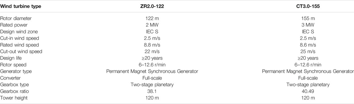
TABLE 1. Wind turbine parameters.
Simpack used a set of generalized coordinates based on a generalized Lagrangian coordinate system (X, Y, Z) and Euler parameters (e0, e1, e2, e3) to establish the equation of motion. A multi-body system consists of interconnected rigid or flexible bodies, each of which has translational and rotational displacements, connected by forces and joint elements that describe their dynamic and kinematic constraints. Generalized inertial force is derived from the virtual work principle, inertial force can be expressed by the mass matrix multiplied by the acceleration vector plus the nonlinear inertial force and stress vector. By collecting all generalized forces acting on the component, an equilibrium equation of the component is derived. Ultimately, the established multi-body system model is shown in Figure 1.
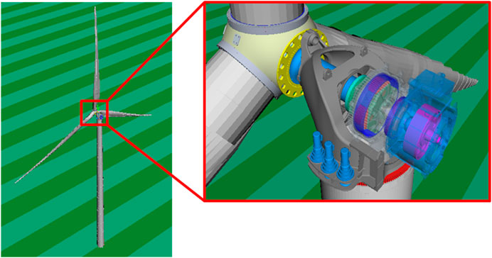
FIGURE 1. Multi-body dynamics analysis model.
Model Validation
To verify the accuracy of the simulation model, field experiments were carried out to compare the simulation and measured results under different working conditions. The test prototype was installed in Tianganghu Wind Farm in Sihong, Jiangsu Province, China. Figure 2 shows the topographic map of the wind farm and the location of the measured wind turbine.

FIGURE 2. Schematic diagram of the topography of the test wind farm.
The test was carried out in accordance with the IEC TS 61400-13 standard (Ossmann et al., 2021), and the test setup of the measurement system is given in Figure 3. The anemometer type to be used in power performance testing to meet the requirements given in IEC 61400-12-1, where the distance to the measured wind turbine is 253 m. The IEC norm requires that anemometer selection account for turbulence characteristics, terrain induced inflow angles, and icing conditions on site. The met mast shall feature redundant wind speed (two top-mounted sensors) and one wind direction (near the hub height), air temperature, and pressure measurements within 10 m hub height. A met unit box will be placed on the flat of the met mast. For measurements throughout the winter, a heated cup anemometer with calibration and transformer unit will be used. The data are sampled at 1 Hz and stored at 10 min mean values, along with the standard deviation, minimum, and maximum values as used in post processing. Data shall be retrieved through internet connection at regular intervals for data validation and further processing.
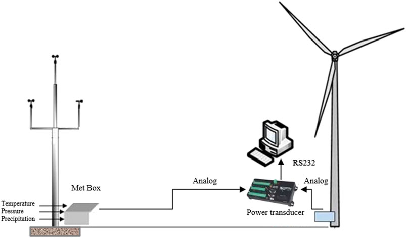
FIGURE 3. Setup of the Measurement System.
The data acquisition system was based on a data logger of type IMC CANSAS-SC16, CANSAS-SC16, CANSAS-DI16 modules, and an on site PC. The signals of meteorological mast and turbine status signals were connected to CAN-Bus modules and digitally transmitted to the main unit. The sampling frequency of signals from meteorological mast is 1 Hz and from wind turbine is 50 Hz. The DAC resolution of IMC is 16 bits, and the cut-off frequency is 2000 Hz. All signals were recorded continuously to the internal hard disk by IMC devices. The data have been transmitted to a PC next to the main unit at the same time, and then all stored data are calculated using the software.
The test was carried out in accordance with the IEC TS 61400-13 standard, and each 10 min of test results constituted a bin with a sampling frequency of 50 Hz. The test lasted for about six months, and a total of 2,917 sets of effective data were collected (Table 2). The wind speed was taken as an interval of 1 m/s, and the data were statistically processed. The effective wind speed ranged from 0 to 19.5 m/s, generally covering all operating conditions of the wind turbine. Wind speed in the range of 5–7 m/s accounted for a relatively high concentration of values.
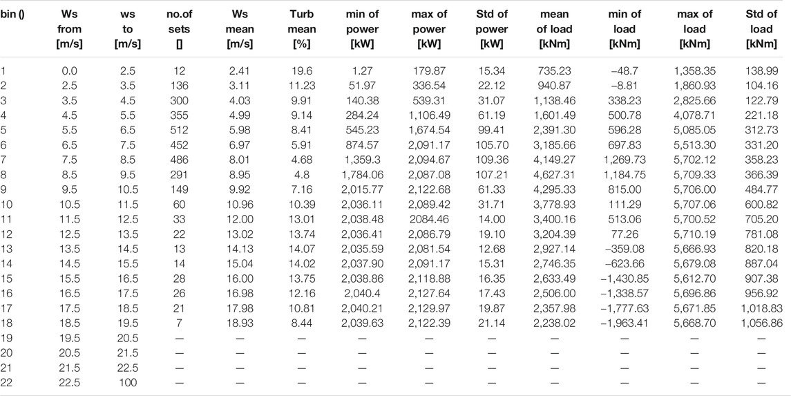
TABLE 2. Statistics of measured data.
According to the wind speed and power characteristics of the wind turbine, the operation of the wind turbine can be divided into several control areas, such as standby area, start grid-connection area, maximum wind energy tracking area, speed limit area, power limit area, and cut out protection area. The variable speed operation of the wind turbine is realized by controlling the output torque of the generator. The controller generates a required torque in the generator air gap to guide the wind turbine to accelerate or decelerate so that the wind turbine operates at the desired speed. When reaching the limit speed, the torque PI controller will change the given torque according to the deviation between the set speed of the generator and the actual feedback value, so that the speed will not increase. Therefore, typical working conditions of the torque control stage were selected in this paper. The wind turbine was started at an average wind speed of 7.49 m/s without yaw or pitch action. Test and simulation time were 240 s, and the comparison is shown in the figure below.
The pitch control stage is another typical working condition of the wind turbine, which can comprehensively reflect the control effect and dynamic response of the wind turbine. When the generator torque reaches the rated value, the pitch controller will begin to work. The variable pitch PI controller determines the given value of the pitch angle according to the speed feedback of the generator, so as to maintain the speed at the set point. The wind turbine was stopped at the average wind speed of 10.49 m/s, yaw and pitch action. The test and simulation time were 240 s, and the comparison is shown in Figure 5 below.
In the torque control stage, it can be seen from Figures 4A,B that both speed and power are relatively stable. Before reaching the grid-connected speed, the maximum error between the simulation results and measured results reached 10%. After reaching the grid-connected speed, the simulation data and measured data quickly converged, in the stable power generation stage from 180 to 240 s, the mean value of measured power is 1,380 kW, and the mean value of simulated power is 1,435 kW, with a difference of about 4%, the fluctuation of simulated power is larger. The simulation mean value of Blade
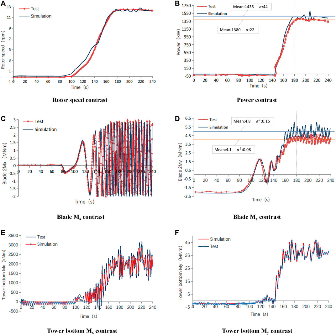
FIGURE 4. Verification of torque control.
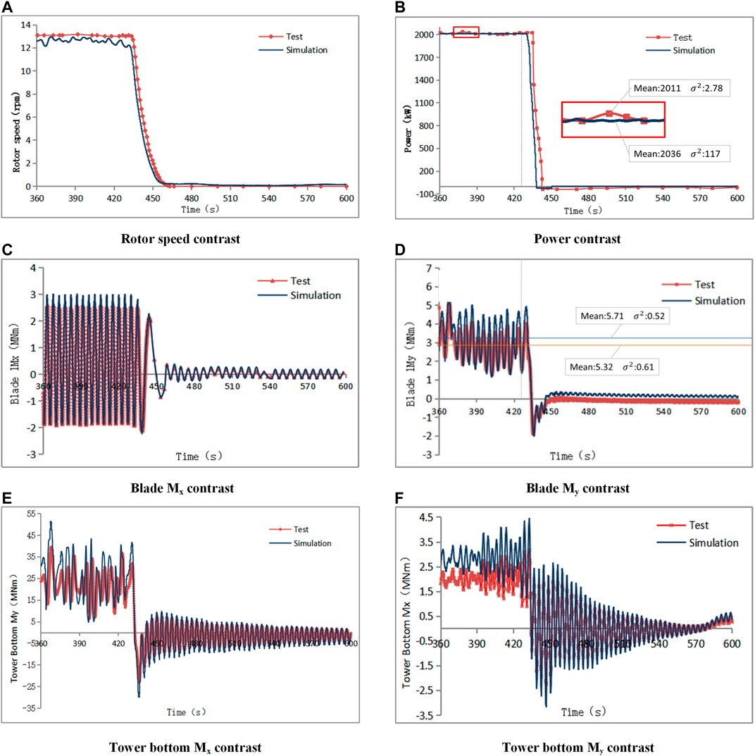
FIGURE 5. Verification of pitch control.
Novel Yaw Strategy
The allowed yaw error by a wind turbine is usually set to two or several fixed values (as shown in Table 3), which is based on experience over time (Germanischer Lloyd, 2010; Chatzopoulos, 2015). It can be seen form Table 3 that when the wind speed is between 0 and 10 m/s, the corresponding yaw threshold is 60°. When the wind speed is between 10 and 35 m/s, the yaw threshold is 45°. When the wind speed is greater than 35 m/s, the yaw threshold is 30°. Obviously, across the whole operating wind speed range of a wind turbine, the yaw threshold is correlated with wind speed.

TABLE 3. Normal yaw error limit.
The Table 3 is a sort of stepwise threshold, and mutations may occur in practical applications. For example, when the wind speed is 10 m/s, the corresponding yaw threshold is 60°, and when the wind speed is 10.1 m/s, the yaw threshold jumps to 45°. At present, the rotor diameter of wind turbine is becoming larger, for the purpose of achieving precise control, the theoretical yaw threshold should vary with the changes in wind speed, so as to adapt to the unsteady change of wind speed and direction.
Calculation Method of Yaw Threshold
Before the yaw threshold is calculated, a set of basic values of yaw error should be determined based on the performance of the wind turbine and past industrial experience, and then the yaw threshold can be accurately calculated by interpolation based on the measured wind speed. According to wind speed c at the current moment, the yaw threshold b at the moment is obtained through linear interpolation, and the yaw threshold b changes dynamically with the average wind speed c. Within a certain wind speed range of c1∼cn, the yaw threshold can be divided into n + 1 segments, as shown in Figure 6 when n = 4.
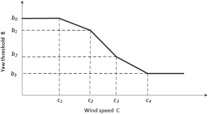
FIGURE 6. Novel yaw threshold b calculation method (n = 4).
Within a certain wind speed range of c1∼cn, the calculation methodology of wind turbine yaw threshold b is shown in Figure 7.
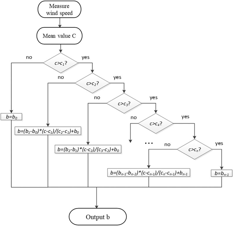
FIGURE 7. Calculation process of yaw threshold.
Optimization Strategy for Large Yaw Error
By measuring the current wind speed, the yaw threshold and actual yaw error at different wind speeds were obtained and compared. When the yaw error is smaller than the yaw threshold, the wind turbine will generate power normally, and when the yaw error is greater than the yaw threshold, the wind turbine will limit power production for t seconds. The yaw deviation is judged again after t seconds, and if the yaw error is still greater than the yaw threshold, the shutdown action will be performed, but if the yaw error is lesser than the yaw threshold, the wind turbine will return to normal power generation state as shown in Figure 8. This strategy not only avoids the shutdown under the conditions of large yaw error and improves availability, but also reduces the load impact on the yaw bearing and improves the safety.
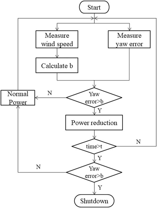
FIGURE 8. Large yaw error optimization strategy.
Results and Analysis
The actual yaw error and yaw threshold are calculated under the given change of wind speed and direction (as shown in Figure 9), with an initial wind speed of 10.67 m/s, which quickly increased to 25 m/s, while wind direction was stable after a rapid change of over 60° in 20 s. In simulating the system, the simulation time was 100 s, and the dynamic response of the wind turbine before and after the large yaw error strategy was optimized was obtained. The position curve of pitch angle is shown in Figure 9A, the output power of model is shown in Figure 9B, the ultimate load on the yaw bearing is shown in Figure 9C, and the ultimate load on the tower top is shown in Figure 9D.
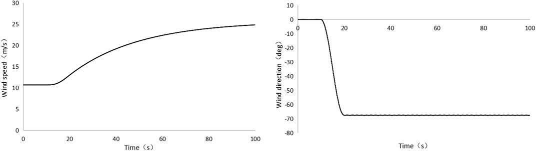
FIGURE 9. Input data of wind speed and direction.
Based on the conditions of wind speed and direction in Figure 9, the actual response of the wind turbine corresponding to three different strategies is shown Figure 10A. It can be found that the pitch angle of the wind turbine is basically constant at the beginning and starts to change around 18 s, and the wind turbine shuts down quickly in normal control methods (before optimization). When using the large yaw error optimization strategy, the wind turbine will reduce the power production, and without trigger the emergency stop sequence. This sudden shutdown in the case of a large gust may cause a greater impact on the yaw system. Some manufacturers in the industry will choose to ignore the influence of yaw error when calculating the loads, so as to avoid large extreme values. To compare the influence of this methodology, this paper also carries out the simulation in this condition, where it can be found that the wind turbine can avoid stopping. However, it is not clear whether this action will have an impact on the operational safety of wind turbines, so it is not generally recommended. Figure 10B shows that the power was limited to 2,000 kW when using new strategy, which is consistent with the settings. Figure 10C gives the yaw bearing loads in three different cases, and when the new strategy is used, the yaw bearing loads can be reduced about 50%. This result can provide instructions for reducing yaw bearing load under special working conditions. Figure 10D shows the loads on the tower top, where the original scheme has the minimum load on the top of the tower due to the shutdown, and when the load of the new scheme is about half that of the scheme where yaw error is negligible. These phenomena show that the new strategy is the best solution.
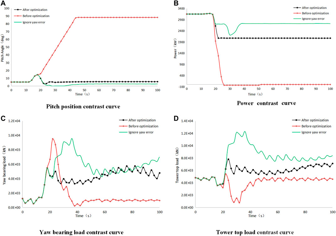
FIGURE 10. Control effects comparison under different control strategies.
Conclusion
This paper used the multi-body dynamics method and constructed the precise multi-flexible body dynamics model of a wind turbine. Since the allowable yaw error of a wind turbine cannot often adapt to the highly variable change characteristics of wind speed and direction under special conditions, an accurate calculation method of allowable yaw error threshold based on measured wind speed and the corresponding optimization strategy of large yaw error are proposed. The dynamic response of the wind turbine was then simulated. The main research conclusions are as follows:
1) The multi-body model of the whole wind turbine established in this paper can accurately describe the dynamic characteristics of the system, which can provide a basis for subsequent yaw strategy research;
2) The precise calculation method of yaw threshold proposed in this paper can provide inputs for the precise control of the wind turbine yaw system and match the specification requirements;
3) The large yaw error optimization control strategy can effectively avoid the unnecessary shutdown of the wind turbine under the large yaw error conditions, reduce the load impact of the yaw bearing, and reduce the ultimate load on the top of the tower.
Data Availability Statement
The original contributions presented in the study are included in the article/Supplementary Material, further inquiries can be directed to the corresponding author.
Author Contributions
YW: methodology, writing—review and editing, and funding acquisition. XC: conceptualization and supervision. BX: conceptualization and supervision. ZL: conceptualization and supervision. All authors contributed to the article and approved the submitted version.
Funding
This work was supported by the first group of 2011 plan of China’s Jiangsu province (Grant No. (2013) 56) and the Fundamental Research Funds for the Central Universities (Grant Number B210202063).
Conflict of Interest
The authors declare that the research was conducted in the absence of any commercial or financial relationships that could be construed as a potential conflict of interest.
References
Astolfi, D., Castellani, F., Becchetti, M., Lombardi, A., and Terzi, L. (2020). Wind Turbine Systematic Yaw Error: Operation Data Analysis Techniques for Detecting it and Assessing its Performance Impact. Energies. 13 (9). doi:10.3390/en13092351
Astolfi, D., Castellani, F., and Natili, F. (2019). Wind Turbine Yaw Control Optimization and its Impact on Performance. Machines 7 (2), 41. doi:10.3390/machines7020041
Bao, Y., and Yang, Q. (2021). A Data-Mining Compensation Approach for Yaw Misalignment on Wind Turbine. IEEE Trans. Ind. Inf. 99, 1. doi:10.1109/tii.2021.3065702
Campos-Mercado, E., Cerecero‐Natale, L. F., Garcia‐Salazar, O., Abundis Fong, H. F., and Wood, D. (2020). Mathematical Modeling and Fuzzy Proportional–Integral–Derivative Scheme to Control the Yaw Motion of a Wind Turbine. Wind Energy. 24 (4), 379–401. doi:10.1002/we.2579
Chatzopoulos, A. (2015). Control Algorithm Description Report. United Kingdom: Garrad Hassan Turbine Engineering(DNV GL).
Chehouri, A., Younes, R., Ilinca, A., and Perron, J. (2015). Review of Performance Optimization Techniques Applied to Wind Turbines. Appl. Energ. 142, 361–388. doi:10.1016/j.apenergy.2014.12.043
Cheng, Y., Xue, Z., Jiang, T., Wang, W., and Wang, Y. (2018). Numerical Simulation on Dynamic Response of Flexible Multi-Body tower Blade Coupling in Large Wind Turbine. Energy. 152, 601–612. doi:10.1016/j.energy.2018.03.137
Dai, J., He, T., Li, M., and Long, X. (2021). Performance Study of Multi-Source Driving Yaw System for Aiding Yaw Control of Wind Turbines. Renew. Energ. 163, 154–171. doi:10.1016/j.renene.2020.08.065
Dai, J., Yang, X., and Wen, L. (2018). Development of Wind Power Industry in China: A Comprehensive Assessment. Renew. Sustainable Energ. Rev. 97, 156–164. doi:10.1016/j.rser.2018.08.044
deCastro, M., Salvador, S., Gómez-Gesteira, M., Costoya, X., Carvalho, D., Sanz-Larruga, F. J., et al. (2019). Europe, China and the United States: Three Different Approaches to the Development of Offshore Wind Energy. Renew. Sustainable Energ. Rev. 109, 55–70. doi:10.1016/j.rser.2019.04.025
Dong, X., Wang, Y., Wang, H., and Kong, L. (2021). Optimised Yaw Model for Adaptive Wind Direction Characteristic Based on a Data‐driven Approach. IET Renew. Power Generation. 15 (1), 237–250. doi:10.1049/rpg2.12020
Germanischer Lloyd (2010). GL Guideline for the Certification of Wind Turbines. Germanischer Lloyd Rules for Classification and Construction.
He, J., Jin, X., Xie, S. Y., Cao, L., Lin, Y., and Wang, N. (2019). Multi-body Dynamics Modeling and TMD Optimization Based on the Improved AFSA for Floating Wind Turbines. Renew. Energ. 141, 305–321. doi:10.1016/j.renene.2019.04.005
He, X., Geng, H., and Mu, G. (2021). Modeling of Wind Turbine Generators for Power System Stability Studies: A Review. Renew. Sustainable Energ. Rev. 143, 110865. doi:10.1016/j.rser.2021.110865
Hu, J., Sun, L., Yuan, X., Wang, S., and Chi, Y. (2017). Modeling of Type 3 Wind Turbines with Df/dt Inertia Control for System Frequency Response Study. IEEE Trans. Power Syst. 32 (4), 2799–2809. doi:10.1109/tpwrs.2016.2615631
Lacal-Arántegui, R. (2019). Globalization in the Wind Energy Industry: Contribution and Economic Impact of European Companies. Renew. Energ. 134, 612–628. doi:10.1016/j.renene.2018.10.087
Li, Y., Castro, A. M., Sinokrot, T., Prescott, W., and Carrica, P. M. (2015). Coupled Multi-Body Dynamics and CFD for Wind Turbine Simulation Including Explicit Wind Turbulence. Renew. Energ. 76, 338–361. doi:10.1016/j.renene.2014.11.014
Liu, Y., Liu, S., Zhang, L., Cao, F., and Wang, L. (2021). Optimization of the Yaw Control Error of Wind Turbine. Front. Energ. Res. 9, 626681. doi:10.3389/fenrg.2021.626681
Ossmann, D., Seiler, P., Milliren, C., and Danker, A. (2021). Field Testing of Multi-Variable Individual Pitch Control on a Utility-Scale Wind Turbine. Renew. Energ. 170, 1245–1256. doi:10.1016/j.renene.2021.02.039
Porté-Agel, F., Wu, Y.-T., and Chen, C.-H. (2013). A Numerical Study of the Effects of Wind Direction on Turbine Wakes and Power Losses in a Large Wind Farm. Energies. 6 (10), 5297–5313. doi:10.3390/en6105297
Sayed, M., Klein, L., Lutz, T., and Krämer, E. (2019). The Impact of the Aerodynamic Model Fidelity on the Aeroelastic Response of a Multi-Megawatt Wind Turbine. Renew. Energ. 140, 304–318. doi:10.1016/j.renene.2019.03.046
Wan, S., Cheng, L., and Sheng, X. (2015). Effects of Yaw Error on Wind Turbine Running Characteristics Based on the Equivalent Wind Speed Model. Energies. 8 (7), 6286–6301. doi:10.3390/en8076286
Wang, S., Nejad, A., Bachynski, E. E., and Moan, T. (2020). A Comparative Study on the Dynamic Behaviour of 10 MW Conventional and Compact Gearboxes for Offshore Wind Turbines. Wind Energy 24, 770–789. 10.1002/we.2602
Keywords: wind turbine, multi-body dynamics method, yaw control, yaw threshold, yaw error strategy
Citation: Wang Y, Cai X, Xu B and Li Z (2021) Study on Novel Yaw Error Strategy for Wind Turbines Based on a Multi-Body Dynamics Method. Front. Energy Res. 9:711927. doi: 10.3389/fenrg.2021.711927
Received: 19 May 2021; Accepted: 21 June 2021;
Published: 06 July 2021.
Edited by:
Wei Jun Zhu, Yangzhou University, ChinaReviewed by:
Davide Astolfi, University of Perugia, ItalyLiang Li, University of Strathclyde, United Kingdom
Copyright © 2021 Wang, Cai, Xu and Li. This is an open-access article distributed under the terms of the Creative Commons Attribution License (CC BY). The use, distribution or reproduction in other forums is permitted, provided the original author(s) and the copyright owner(s) are credited and that the original publication in this journal is cited, in accordance with accepted academic practice. No use, distribution or reproduction is permitted which does not comply with these terms.
*Correspondence: Yazhou Wang, d2FuZ3lhemhvdUBjdG5laS5jb20=