 Deng Lilin1
 Wang Yuqing
 Ni Muyi
- 1Science and Technology on Reactor System Design Technology Laboratory, Nuclear Power Institute of China, Chengdu, China
- 2Sino-French Institute of Nuclear Engineering and Technology, Sun Yat-sen University, Guangzhou, China
- 3The Institute of Advanced Science Facilities (IASF), Shenzhen, China
210Po, a highly toxic element with strong volatility, is one of the main source terms of a Gen-IV lead-cooled fast reactor (LFR). Therefore, the radioactive safety caused by 210Po has become an important topic in LFR-related research. In order to simulate the behavior of 210Po in an LFR, this work developed a multi-physics model of an LFR from the perspective of radioactive transport. Considering the effects of nuclide decay, cover gas leakage, containment ventilation, and Po aerosol deposition, a comprehensive simulation was carried out to evaluate the sensitivity of those effects on the 210Po distribution in detail. Preliminary results indicate that during normal operation, most of the 210Po in the LBE exist in the form of PbPo, and around 10–9 of 210Po could evaporate from the LBE into the cover gas, and then further leak into the containment. In addition, even if the leakage rate of 210Po in the cover gas into the containment is maintained at 5‰ per day, due to the deposition of Po aerosol, the 210Po contamination on the inner surface of the containment is still below the radioactivity concentration limits.
Introduction
As one of the generation-IV (Gen-IV) nuclear power system, the lead-cooled fast reactor (LFR) is expected to be the first concept to achieve industrial demonstration (Lorusso et al., 2018; Nuclear Power, 2019). Lead–bismuth eutectic (LBE) is selected as the primary coolant for the LFR due to its neutronic economic and good thermal hydraulic properties (Dierckx et al., 2014). However, during normal operation of the LFR, 210Po, a highly toxic element with strong volatility, will be produced in the LBE coolant, which will induce a new radioactive safety problem.
In the purpose of the occupational safety and public health, ICRP and nuclear power countries have specified healthful working conditions and given the exposure limits of 210Po. In NRB-99 of Russia, the occupational annual limit on intake (ALI) is settled as 6.70 × 10³ Bq, and the safety permission of air concentration is below 2.7 Bq/m3 (Pankratov et al., 2004). For the U.S. NRC regulation of 10 CFR Part.20, the derived air concentration (DAC) of 210Po is settled as 1.1 × 10⁵ Bq/m3, while one DAC is equal to allowable maximum air concentration at the breathing rate of 1.3 m3/h for 2,000 working hours per year. And the ALI for ingestion and inhalation are 1.11 × 10⁵ Bq and 2.22 × 10⁴ Bq, respectively (Nuclear Regulatory Commission 10CFR, 2017). In China, the National Standard GB18871-2002 rules mention the ALI of 210Po as 8.3 × 10⁴ Bq, and the exemption concentration as 104 Bq (Mao, 2014), the National regulation on 210Po of RA, US, and CN are given in Table 1.
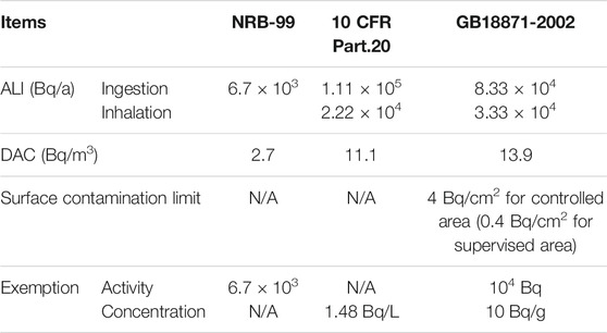
TABLE 1. National regulation on 210Po of RA, US, and CN.
Multi-Physics Model for Po Transport in the LFR
Source Term of Po in the LFR
210Po has a short half-life of 138.4 days (Ram et al., 2019) and is the β decay product of 210Bi (Loewen, 2005). During the normal operation of the LFR, 210Po evaporates from the LBE coolant as a simple substance and a chemical form of PbPo, and then accumulates in the cover gas. Accompanied with the leakage of cover gas, 210Po is released into the containment (Feuerstein et al., 1992), which results in significant radioactive contamination and potential occupational exposure during maintenance.
Po Behavior in the LFR
Physical and Chemical Properties of Po in the LFR
As shown in Figure 1, 210Po exists in the form of Po, PbPo, and H2Po in a typical LFR. And it is immediately apparent that the migration behavior is affected by the key processes of evaporation, decay, diffusion, convection in flow, deposition in air, and chemical reactions with other substances.
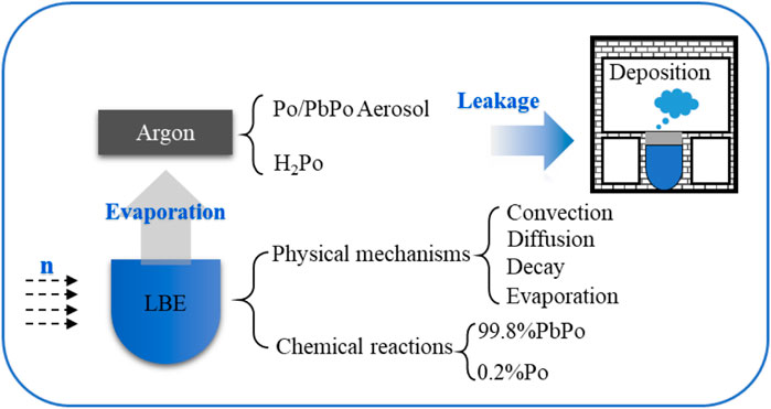
FIGURE 1. Migration characteristics of polonium in the LBE reactor.
In LBE coolant, once the Po is generated from the 210Bi decay, it will have a reaction with Pb immediately and form the compound of PbPo with stable chemical properties. For example, when the coolant temperature is around 673K, only 0.2% (
For an accident condition, such as steam generator tube rupture (SGTR), PbPo may directly come in contact with steam, and highly volatile radioactive compounds such as H2Po will be produced, which will make the Po behavior even more complicated. The chemical equations are as follows:
The fundamental properties of Po, PbPo, and H2Po are summarized in Table 2.
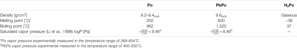
TABLE 2. Po, PbPo, and H2Po foundation properties (Feuerstein et al., 1992).
Mass Flow of Po in LFR
To gain insight into the characteristic feature of 210Po in LFR on a normal operation, the mass flow map of 210Po had been clearly drawn in Figure 2.
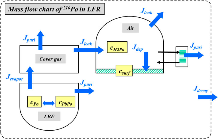
FIGURE 2. The molecule flowchart of 210Po in an LFR.
In LBE coolant,
• Accompanied with neutron irradiation, the isotope 210Bi is produced, and then we have the concentration of Bi as cBi210 (mol/m3), with a decay rate
• 210Bi decays into 210Po, then we have the concentration of Po as
• Define the decay of Po,
• Define the purification rate of Po in LBE,
• Define the Po and PbPo evaporate flux into cover gas at the LBE–gas interface as
Then the molecule balance equation for each species in LBE can be written as Eq. 4:
In cover gas.
• Define the decay rate of Po,
• Define the purification rate of Po,
• Define the leakage rate of Po into the containment,
Then the molecule balance equation for each species in cover gas can be written as Eq. 5:
In containment.
• All the PbPo are assumed to be reacted with H2O in air, to generate H2Po in the containment,
• Define the decay rate of H2Po,
• Define the deposition rate of H2Po,
• Define the purification rate
Then the molecule balance equation for each species in the containment can be written as Eq. 6:
And due to the H2Po aerosol deposition, there will be surface contamination on the ground of the containment, which is calculated as follows:
From above Eqs. 4–7, a numerical relationship between the 210Po transport and multi-physics environment of LFR had been finally established.
Then a particular emphasis should be put on the evaporation model of Po and PbPo, which dominates how much of the 210Po source will escape from the restraint of LBE. According to Raoult's law for ideal gas, the vapor pressure of dilute solution is equal to the vapor pressure of a pure solvent multiplied by the mole fraction of the solvent in solution at the special temperature (Feuerstein et al., 1992; Loewen, 2005). And the saturated vapor pressure, which is frequently cited, is listed in Table 2.
There is a general consensus that the evaporation equilibrium of Pb/PbPo can always be achieved in microscale on the surface of LBE coolant. Then the evaporation flux can be constructed as an equation of saturated vapor pressure andreal-time vapor pressure.
where
Multi-Physics Frame and Numerical Models
Multi-Physics Frame
In order to provide the specific parameters in the multi-physical field, the multi-physics coupling frame was established and the causal link between each physics had been found out in Figure 3. The flow field and the heat transfer field are coupled strongly, while the flow heat transfer field and the concentration field are coupled weakly. By taking the output of thermal fluid (
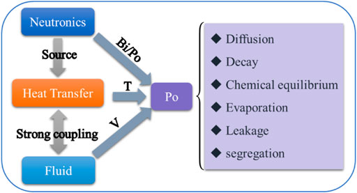
FIGURE 3. The multi-physics model of Po migration in an LFR.
A two-dimensional axisymmetric geometric structure is utilized in this model, according to the typical LFR concept. The main components that have an effect on the source term transport behavior are taken into consideration, including reactor core, heat exchanger, pump, purification system, cover gas, and containment. The material library covers the main candidate materials used in the LFR.
Fluid Flow Model
In order to improve the utilization of computing resources, a porous medium model is modified to the descript 210Po behavior in core and heat exchanger (HX), and the algebraic y + model is utilized to compute the LBE turbulence, which can couple porous media and laminar flow automatically. In reality, a porous media model is frequently adopted in the nuclear industry to simulate the reactor core or HX, which validates a good agreement with the operation condition (Koloszar et al., 2014). The governing equations of the LBE flow are shown as follows:
The first equation is the momentum conservation equation, and the second equation is the mass conservation equation. The Brinkman equation is used to describe the fast flow in saturated porous media, where
The real reactor core is assembled by of tens of thousands of fuel rods vertically. In the simulation, we reasonably simplified the structure of the reactor core and HX as anisotropic porous media, and assumed that LBE flows out mainly from the z-axial direction but rarely from the r-axial direction. Then properties of porous media are determined by two physical quantities, that is, porosity and permeability. The real porosity of the LBE reactor core is 0.2–0.4 (Koloszar et al., 2015). In this model, the porosity of the core is 0.3 and the porosity of the HX is 0.62 (Koloszar et al., 2014). And the permeability is calculated by Darcy’s formula, which is given as follows:
where Q is the mass flow (kg/s),
Finally, the LBE coolant circulation in a reactor vessel was established. Heated by the reactor core and driven by buoyance, the LBE coolant flows up. Then driven by the pump, the LBE coolant will flow down, through HX, and back to the core. The entire flow field (
Heat Transfer Model
The heat transfer model is also based on a porous medium model, and the general governing equation of heat transfer is as follows:
where
where
Molecule Transfer Model
Since
where
Numerical Modeling for 210Po in a Typical LFR
Modeling Condition
In order to provide input for a simulation case, several typical LFR concepts in the world are investigated, and the main operation parameters are listed in Table 3 (Zrodnikov et al., 2008; Zrodnikov et al., 2011; Didier et al., 2015). The typical ventilation rate is one volume turnover per hour according to the PWR operation experience. In this work, we assume an atmosphere purification system for the containment, which has a ventilation rate of 0.5/h and 210Po remove efficiency of 95%. According to IPPE experience, lifetimes of 210Po aerosol range from 60–80 s on equipment to 100–150 s in the containment room. And practically, the aerosol lifetimes are usually selected as 100 s for calculation (Yefimov et al., 1997). Besides, the influence of leakage is also the key factor that has to be taken into consideration. As a baseline, the leakage rate of cover gas is assumed as 5‰ per day, and the leakage rate of the containment is assumed as 4‰ per day.
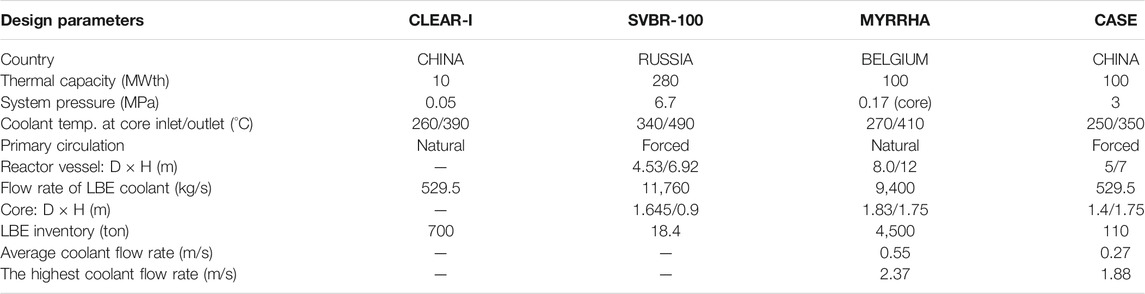
TABLE 3. Operation parameters of CLEAR, SVBR, MYRRHA, and CASE in this work (Zrodnikov et al., 2008; Zrodnikov et al., 2011; Didier et al., 2015).
210Po Distribution in LFR
Under a normal operation condition, the temperature field of LBE ranges from 610 to 670K, and on the surface for Po/PbPo evaporation, it is around 660K. The high-temperature LBE flows up out of the core and down into the HX and is then driven by the main pump flows back into the core. This is the primary cooling loop of the LBE in the reactor vessel. Then we coupled the LBE thermal fluid with cover gas to figure out the entire temperature field and velocity field in the LFR vessel, as shown in Figures 4, 5.
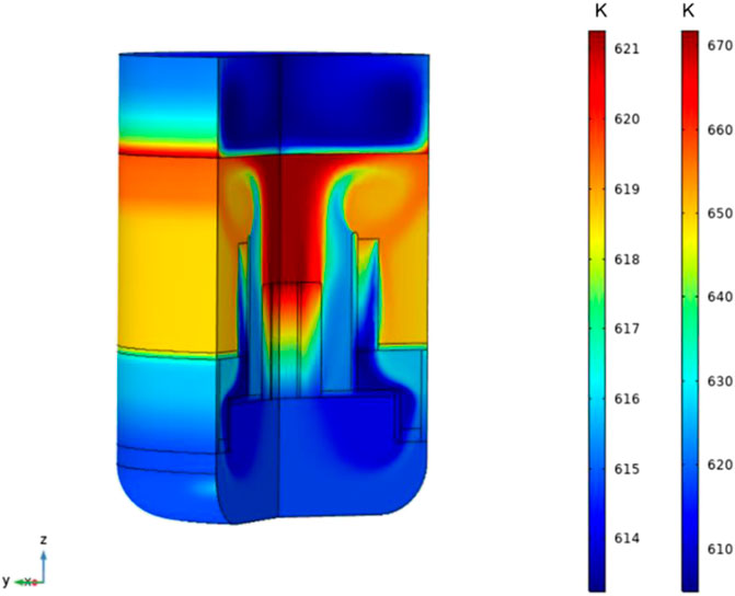
FIGURE 4. The temperature of LBE and cover gas in an LFR vessel at a steady state.
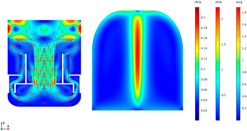
FIGURE 5. The flow field of LBE, Ar, and air in an LFR vessel and containment at a steady state.
Then the 210Po concentration field and transport map were computed with environmental inputs of
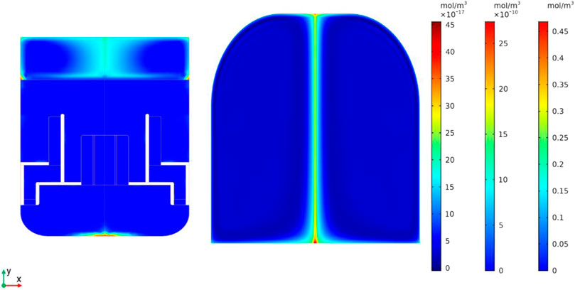
FIGURE 6. The 210Po transport in LFR vessel and containment at a steady state.
As shown in Figure 7, the average concentration of 210Po in LBE vs. time is calculated during 100 days from start-up. Under normal conditions, the 210Po concentration will reach equilibrium within 30 days. And the concentration of Po in LBE is around 1.08 × 10¹⁰ Bq/kg, which is far beyond the exemption concentration according to Chinese regulation (GB18871-2002). In cover gas, the Po concentration is 6.58 × 10³ Bq/L, which is also 2–3 orders of magnitude higher than one DAC value. The concentration of Po in the containment is ∼1 × 10⁻³ Bq/L, which is below the limitation in law.
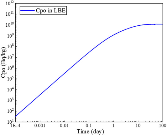
FIGURE 7. The average concentration of Po in LBE during 100 days.
Impact Factors of the Po Transport
Operation Temperature
Since the Po/PbPo evaporation rate is very sensitive to temperature, the influence of operation temperature is taken into analysis. Six different temperature ranges for LFR operation were simulated by adjusting the efficiency of the HX. And the corresponding average concentrations of 210Po in cover gas and containment were obtained, which is shown in Figure 8.
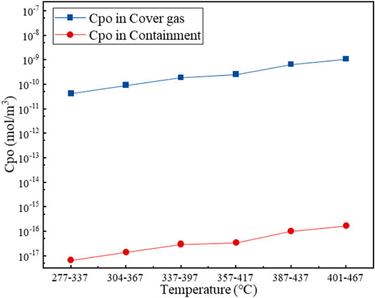
FIGURE 8. The average concentration of Po in cover gas and containment under different temperature of evaporating interface.
Apparently, from Figure 8, a simple conclusion can be made that the evaporation rate of 210Po from LBE to cover gas will increase rapidly with the higher temperature on the LBE–gas interface. While the 210Po concentration in cover gas is increasing, the 210Po concentration in the containment is increasing in the same proportion. However, at high operation temperature like 401–467°C, the concentration of 210Po in the containment is 63.2 Bq/L, which is a bit higher than one DAC value.
Deposition Rate
A comprehensive analysis was made for all the influential factors (including deposition, ventilation, leakage, and decay) on the 210Po concentration in the containment, which is shown in Table 4. It is obvious that the phenomenon of aerosol deposition is the key process affecting aerosol concentration in containment, based on the assumption in this work. However, the aerosol deposition rate is strongly dependent on the dynamic particle size and density, which will guide our future experiment.
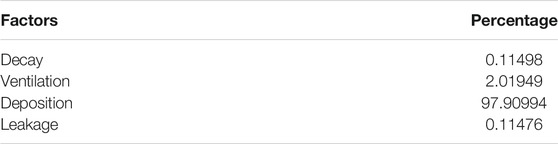
TABLE 4. Influence factors on 210Po concentration in the containment.
We simulated the total surface contamination due to 210Po deposition in the containment and its accumulation during 100 days normal operation. As shown in Figure 9, after 10 days operation, the 210Po activity on the ground of the containment exceeds the limit value of 4 × 10³ Bq/m2 specified in the China regulation GB18871-2002. Therefore, it is very important that special decontamination measures must be developed to control the 210Po and avoid radioactivity harms to maintenance staff.
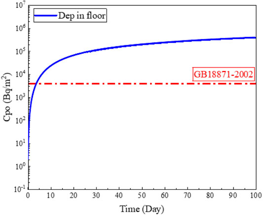
FIGURE 9. The surface contamination due to 210Po deposition in the containment (100 days).
Leakage Rate
In the real operation, the problem of cover gas leakage is inevitable. In order to better study the influence of leakage from the safety perspective, the leakage fraction per day of cover gas was varied from 0.01% to 0.02, 0.04, 0.08, 0.16, and 0.32%; the 210Po activity in the containment was calculated; and the parameter sensitivity was taken in the analysis.
In Figure 10, the average activity of 210Po in the containment is very sensitive to the leakage rate of the cover gas. Once the leakage rate is higher than 0.01, the 210Po activity in air will exceed the one DAC limit. In order to control the 210Po release and ensure the LFR in a safety state, the leakage rate of the cover gas should be kept below 0.01 strictly, and as low as possible. In case of serious radioactive leakage, the purification system should be quickly started to control the 210Po activity.
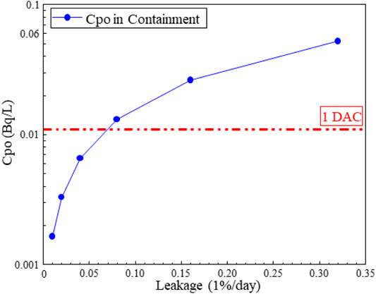
FIGURE 10. Average activity of 210Po in the containment under different leakage rates of cover gas.
Purification System
IPPE developed the techniques of the alkaline extraction of polonium from LBE (Yefimov et al., 1997). And MIT developed the polonium extraction techniques of rare-earth filtering and polonium hydride stripping (Larson, 2002). All these research studies show that the extraction and purification efficiency of 210Po in a real LFR have the potential to reach 90–99%. Therefore, it is reasonable to assume a purification efficiency of 95% to analyze the sensitivity of purified fraction to the 210Po activity in the containment. While the leakage rate is fixed, we modified the flow fraction into the purification system (
where m is the LBE mass flow rate (kg/s),
Apparently, in Figure 11 above, the purification fraction has a significant influence on the activity of 210Po in the containment. A high purification fraction could reduce the 210Po contamination in the containment effectively, but significantly increase the load of the LBE purification system and the operation cost. While the purification fraction is less than 0.01, the 210Po concentration will exceed one DAC limit. And while the purification fraction is more than 0.05, the decrease rate of 210Po in the containment slowed down gradually. To make a compromise between nuclear safety and economy, a purification fraction of ∼0.05 is recommended.
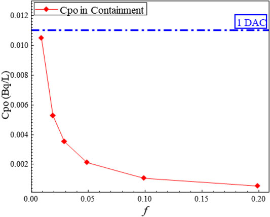
FIGURE 11. The average activity of 210Po in the containment under different purification fractions.
Discussion and Conclusion
As a summary of the aforementioned simulation results, for a typical LFR, most of the 210Po accumulate in the LBE coolant can be restrained as a form of PbPo; only ∼10–9 of them could evaporate into cover gas, which is strongly dependent on the temperature on the LBE–gas interface. The aerosol deposition seems to be a positive feature in that it takes the radioactive 210Po down onto ground and restrains the DAC value in air. However, the surface contamination and aerosol resuspension are newly emerging issues. Ventilation combined with the atmosphere purification system is an artificial and reliable approach for Po decontamination.
In addition, some major safety challenges of polonium in LFR still exist. The unknown phenomena and their effects on polonium transport behavior need to be further and deeply explored, such as the oxygen control in LBE, material corrosion products, and impurity filtration. In the next step, more mechanisms of Po transport in the real operation condition and design base accident (DBA) condition will be taken into consideration.
Data Availability Statement
The raw data supporting the conclusions of this article will be made available by the authors, without undue reservation.
Author Contributions
DL: paper writing, data preparation, and systematic analysis. WY: program coding and sensitivity analysis. ZZ and HB: validation and verification. HJ and WJ: module coding. NM: theoretical model development.
Funding
This study was funded by the National Defense Pre-Research Foundation of China (grant no. 201-XXXX0404-fzsdx-Tm06) and the Fundamental Science on Nuclear Wastes and Environmental Safety Laboratory (grant no. 18kfhk04).
Conflict of Interest
The authors DL, ZZ, and HB were employed by the company Nuclear Power Institute of China.
The remaining authors declare that the research was conducted in the absence of any commercial or financial relationships that could be construed as a potential conflict of interest.
Publisher’s Note
All claims expressed in this article are solely those of the authors and do not necessarily represent those of their affiliated organizations, or those of the publisher, the editors and the reviewers. Any product that may be evaluated in this article, or claim that may be made by its manufacturer, is not guaranteed or endorsed by the publisher.
References
Buongiorno, J. (2001). Conceptual Design of a Lead-Bismuth Cooled Fast Reactor with In-Vessel Direct-Contact Steam Generation. MIT. Nuclear Engineering Department. Ph.D Thiesis.
Buongiorno, J., Loewen, E. P., Czerwinski, K., and Larson, C. (2017). Studies of Polonium Removal from Molten Lead-Bismuth for Lead-Alloy-Cooled Reactor Applications. Nucl. Technology. 147 (3), 406–417. doi:10.13182/nt04-a3539
Didier, D. B., Hamid, A. A., Peter, B., and Leysen, P. (2015). The MYRRHA ADS Project in Belgium Enters the Front End Engineering Phase. Phys. Proced. 66, 75–84. doi:10.1016/j.phpro.2015.05.012
Dierckx, M., Van Dyck, D., Vermeeren, L., and Bogaerts, W. (2014). Research towards Ultrasonic Systems to Assist In-Vessel Manipulations in Liquid Metal Cooled Reactors. IEEE Trans. Nucl. Sci. 61 (4), 2024–2033. doi:10.1109/tns.2014.2303951
Feuerstein, H., Oschinski, J., and Horn, S. (1992). Behavior of Po-210 in Molten Pb-17Li. J. Nucl. Mater. 191-194, 288–291. doi:10.1016/s0022-3115(09)80052-4
Koloszar, L., Buckingham, S., and Planquart, P., (2015). MyrrhaFoam: A CFD Model for the Study of the thermal Hydraulic Behavior of MYRRHA, 16. Chicago, IL: NURETH-.
Koloszar, L., Buckingham, S., and Planquart, P., (2014). CFD Simulation of the Thermohydraulic of the MYRRHA ReactorTHINS 2014 International Workshop. Modena, Italy.
Larson, C. L. (2002). Polonium Extraction Techniques for a Lead-Bismuth Cooled Fast Reactor, Doctoral dissertation. Cambridge, USA: Massachusetts Institute of Tehcnology. Master Thesis.
Li, N., Yeifimov, E., and Pankratov, D. (1998). Polonium Release from an ATW Burner System with Liquid Lead-Bismuth Coolant. Los Alamos Natl. Lab., 836, 1–10.
Loewen, E. (2005). Investigation of Polonium Removal Systems for Lead-Bismuth Cooled FBRs. Prog. Nucl. Energ. 47, 586–595. doi:10.1016/j.pnucene.2005.05.061
Lorusso, P., Bassini, S., Del Nevo, A., Di Piazza, I., Giannetti, F., Tarantino, M., et al. (2018). GEN-IV LFR Development: Status & Perspectives. Prog. Nucl. Energ. 105, 318–331. doi:10.1016/j.pnucene.2018.02.005
Mao, L. (2014). Preliminary Analysis of Polonium-210 Behavior for Lead-based Reactor. Hefei, China: University of Science and Technology of China. Master Thesis.
Nuclear Regulatory Commission 10Cfr, . (2017). Available at: http://www.nrc.gov/reading-rm/doc-collections/cfr/part020/appb/polonium-210.html. 2017 Accessed March 25, 2021.
Pankratov, D. V., Efimov, E. I., Toshinskii, G. I., and Ryabaya, L. D. (2004). Analysis of the Polonium Hazard in Nuclear Power Systems with Lead-Bismuth Coolant. At. Energ. 97 (2), 559–563. doi:10.1023/b:aten.0000047682.88612.e1
Ram, R., Vaughan, J., Etschmann, B., and Brugger, J. (2019). The Aqueous Chemistry of Polonium (Po) in Environmental and Anthropogenic Processes. J. Hazard. Mater. 380, 120725. doi:10.1016/j.jhazmat.2019.06.002
Yefimov, E., Pankratov, D., and Ignatiev, S. (1997). Removal and Containment of High-Level Radioactive Polonium from Liquid Lead-Bismuth Coolant. MRS Proc. 506, 679. doi:10.1557/PROC-506-679
Zrodnikov, A. V., Toshinsky, G. I., and Komlev, O. G., (2008). Innovative Nuclear Technology Based on Modular Multi-Purpose Lead–Bismuth Cooled Fast Reactors. Prog. Nucl. Energ. 50 (2-6), 170–178. doi:10.1016/j.pnucene.2007.10.025
Keywords: polonium, LBE, fast reactor, Gen-IV, nuclear safety
Citation: Lilin D, Yuqing W, Zian Z, Bochen H, Jiewei W, Jianbo H and Muyi N (2021) Multi-Physics Model Development for Polonium Transport Behavior in a Lead-Cooled Fast Reactor. Front. Energy Res. 9:711916. doi: 10.3389/fenrg.2021.711916
Received: 19 May 2021; Accepted: 25 June 2021;
Published: 30 July 2021.
Edited by:
Shanfang Huang, Tsinghua University, ChinaReviewed by:
Feng Xie, Tsinghua University, ChinaQin Zeng, South China University of Technology, China
Copyright © 2021 Lilin, Yuqing, Zian, Bochen, Jiewei, Jianbo and Muyi. This is an open-access article distributed under the terms of the Creative Commons Attribution License (CC BY). The use, distribution or reproduction in other forums is permitted, provided the original author(s) and the copyright owner(s) are credited and that the original publication in this journal is cited, in accordance with accepted academic practice. No use, distribution or reproduction is permitted which does not comply with these terms.
*Correspondence: Ni Muyi, bmltdXlpQG1haWwuc3lzdS5lZHUuY24=