 Yao Yao1,2
 Cao Jun-hua
 Li Ke
Li Ke- 1Department of Electronic Engineering, Shantou University, Shantou, China
- 2Key Lab of Digital Signal and Image Processing of Guangdong Province, Shantou, China
- 3Dalian Naval Academy, Dalian, China
With the rapid development of renewable energy, the scale of China’s power grid with renewable energy has become much bigger than ever; as a result, we are facing severe challenges in the inspection and maintenance work of power grids that use renewable energy. Focusing on the shortcomings of the traditional manual inspection methods, this paper studies and proposes an optimization algorithm of automatic inspection of Unmanned Aerial Vehicles (UAVs) to improve the efficiency and cost of the inspection and maintenance work of renewable energy power grids. Firstly, the communication network of the swarm intelligence system has been established to transmit the local information sensed by each UAV in real time. Secondly, according to the sensing ability of UAVs, the segmentation model of UAVs overlapping sensing areas is established, which effectively reduces the probability of overlapping UAVs sensing areas. Thirdly, according to the difference between the coverage value and the effective coverage index of each point in the sensing area, the optimization function of the coverage index is given, which makes the UAV give priority to the inspection area with the lower coverage value. Finally, when a UAV completes a local coverage task, the traction speed is introduced to prevent the UAV from stopping, which ensures that the inspection task of the whole area can be completed in a limited time. The numerical simulation results show that the algorithm can effectively control the UAVs to complete the inspection task in the specified area, and compared with the single UAV inspection method, this algorithm can greatly improve the inspection efficiency and reduce the inspection cost.
Introduction
Renewable energy refers to wind energy, solar energy, water energy, biomass energy, geothermal energy, and other non-fossil energy, and it is thus clean energy. Renewable energy is a type of green and low-carbon energy, which is an important part of China’s multi-wheel drive energy supply system. It is of great significance to improve the energy structure, protect the ecological environment, cope with climate change, and achieve sustainable economic and social development (Dieter and Jennifer, 2008; Poonam et al., 2020). In 2020, China’s renewable energy power generation will reach 2214.8 billion kilowatt-hours, with a year-on-year growth of about 8.4%. By the end of 2020, China’s renewable energy power generation capacity will reach 934 million kilowatts, a year-on-year growth of about 17.5% (Cai, 2020). With the continuous expansion of the scale of China’s power grid with renewable energy, the area of inspection and maintenance work of power grids is now facing increasingly severe challenges. Traditional manual inspection methods are inefficient, and inspectors experience high work intensity and significant danger (Yin, 2016; Zhou et al., 2018). The current Unmanned Aerial Vehicle (UAV) inspection mainly relies on remote control by ground operators, which has high technical requirements for UAV operators. Due to the vast area of China’s power grid that is to be inspected and the low efficiency of single UAV inspection, rotor UAVs for power inspection based on Swarm intelligence has become an inevitable trend.
Compared with the traditional single-UAV inspection method (Burciu, 2012; Stone et al., 2014; Jiang et al., 2020), the collaborative inspection of UAVs has the advantages of low cost and high efficiency, which can greatly improve the inspection speed and positioning accuracy. The key of UAVs autonomous inspection method is to realize the coverage control of the unknown area by UAVs. The essence of area coverage control is to design a UAV control method based on the relationship between the sensing model of the UAV and the distribution of information in the area so that the inspection task can be completed. Currently, the most commonly used UAV inspection method is sweeping inspection, that is, to control the formation of the UAVs to make them navigate along an appropriate track in a specific formation to complete the inspection task of the target area (Che et al., 2011; Wang et al., 2020). This method can complete the inspection task in a simple environment, but it has poor autonomy and low efficiency in a complex environment.
Aiming at the shortcomings of existing means, improving the autonomy and efficiency of the UAV system is the main purpose of our study. The advantage of the optimization algorithm of UAV autonomous inspection is that it can efficiently map the target area, and has the characteristics of high security and adaptability. The basic idea of the optimization algorithm is to build a swarm intelligence to make each UAV complete the task assignment of the sub-areas by communicating with the neighboring UAVs, which simplifies the original co-fixed area coverage problem (Cortés et al., 2005; Xiang et al., 2020; Zhang et al., 2020). This paper establishes an optimization algorithm model of UAV autonomous inspection and analyses the effects of the number of UAVs, effective coverage value, and other parameters on the efficiency of UAV autonomous inspection.
Basic Principle of the Optimization Algorithm
The Communication Topology and Dynamic Description of UAVs System
Communication within the UAV system is an important part of the UAV’s cooperative coverage problem. The communication topology of the coverage network composed of UAVs is given based on graph theory.
In this paper, the problem of inspection in a fixed area under ideal conditions is studied. Therefore, the following assumptions are given:
Suppose 1. The communication network of the UAV system is always connected, and its communication topology is an undirected graph.
Suppose 2. The surface to be covered is smooth, and every UAV moves on a plane.
Firstly, the definition of the two-dimensional inertial coordinate system
Based on the coordinate system
where
The Sensing Area Model of UAV
When performing the inspection task, each UAV will be equipped with a vertically downward detection device. Assuming that the divergence angle of each detection device is α, the sensing area of UAV
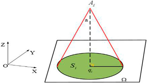
FIGURE 1. Diagram of the sensing area of UAV.
The sensing area model of UAV
Where
The Coverage Efficiency Optimization Index in the Fixed Area
The main task of inspection with UAVs system is to cover the task area Ω with the sensing areas of UAVs so that the detection degree of each point in Ω can reach an effective level, that is, effective coverage.
In order to give the coverage efficiency index of the UAVs inspection system, the definition of effective coverage of points in the fixed area is given first. This is because the information accumulation of points in the fixed area acquired by UAVs using sensors increases with time, that is, the effective coverage level of a point in the area increases with time, for the position
Where g(z,q) is the sensing capacity function of each UAV. Assuming that g(z,q) is proportional to z and g(z,q) is dependent on z only, the sensing capacity of each UAV in the system is equal because the z of each UAV in the system is equal. Let C be the effective coverage of each point of Ω in the area, then the effective coverage of all points in the inspection area by UAVs is defined as follows:
Definition 1If all points in the region Ω are covered and meetwhere
Undirected Sensing Set Segmentation
Reducing the overlap between sensing areas of adjacent UAVs is beneficial to improve the efficiency of marine coverage. Using the segmentation methods in references (Papatheodorou et al., 2016; Tian et al., 2020b), a sensing set segmentation method that can avoid overlapping sensing sets between adjacent UAVs is given below.
where z represents the distance between the UAV and the objective. With the increase of z, the sensing capability gradually decreased. So the sensing set segmentation depends on the z, the overlapping area belongs to the sensing area of UAV that z is smaller.
It can be known from Eq. 6 that When zi= zj, their sensing ability is equal, so for the undirected sensing set, the sensing overlapping area is segmented according to its full symmetry and segmentation method (6), as shown in Figure 2.
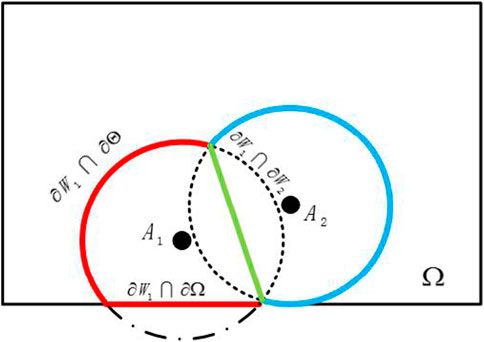
FIGURE 2. The diagram of segmentation of undirected sensing area.
As shown in Figure 2,
The boundary
In which
Design of Motion Control Law of UAVs
According to the formula of coverage efficiency index (5) of the UAVs inspection system, the coverage efficiency index problem of the UAVs inspection system can be described as the optimization problem (Fan et al., 2019; Zhang et al., 2021) for the minimum value of
For the optimization problem described by Eq. 8, it is difficult to directly obtain the gradient information of
Because the points beyond the sensing area of UAV can not be sensed, that is,
After dividing the sensing area of each UAV according to the dividing method of Eqs 7, 10 can be further expressed as follows:
To find the solution of the gradient of the variables to be optimized in the function H(t) according to Leibniz’s integral rule (Tian et al., 2020a), the process was described as follows:
Where
For
In Equation 14,
Where
Based on Eq. 15, the expected optimal speed of each UAV in the UAV system is designed as follows:
The optimal speed of UAVs based on the gradient descent method of the variable
Firstly, the points that have not been effectively covered in the task area are defined as the following sets:
Where
A rule was set that a unique point
Where
Above all, the expected optimal speed of each UAV
The purpose of designing the acceleration of the UAV is to keep the current speed of the UAV consistent with the expected optimal speed. Therefore, if the acceleration
Where
Simultaneous Cooperative Coverage Algorithm of Fixed Area Covered by UAVs
According to the above content, the pseudo-code of the optimization algorithm of the UAVs system is obtained as follows:
Input: fixed area Ω, dynamic model of UAV, initial state of UAVs system, control gain parameter k1,k2,k3; Output: Output the optimal trajectory of each UAV; 1: Initialization: establishing an UAV object, and inputting initial position information and initial speed information of the UAV; Gain parameters of control rate, etc: 2: Build a task area model: 3: Calculating respectively the motion state information of each UAV Ai, i ∈ IN, and setting the initial time k = 1; 4: while J(t) > 0 do 5: For each UAV do 6: If H(t) ≠ 0; 7: Calculate the expected optimal speed of UAV Ai, i ∈ IN according to (16); 8: else 9: Calculate the expected optimal speed of UAV Ai, i ∈ IN according to (19); 10: End 11: Use (21) to calculate the acceleration Ui of UAV Ai; 12: Calculate the actual speed of UAV Ai at this time 13: According to the dynamic equation, calculating the position information Xi(k+1) of the UAV Ai at the next moment; 14: End 15: k = k + 1; 16: End
Numerical Simulation
In order to verify the feasibility and effectiveness of the proposed method, a numerical calculation method is used to verify the method. Set the inspection area as a square area with a side length of 20 km. In total, six UAVs were used to cover the task area, and the initial position of each UAV is shown in the Table 1.
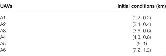
TABLE 1. Initial conditions of UAVs.
Assuming the effective coverage value
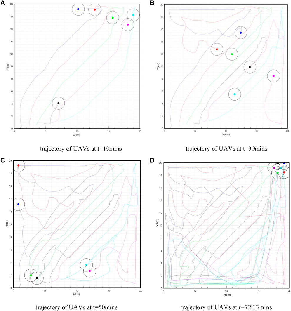
FIGURE 3. Trajectory of UAVs at different time.
The coverage of the whole task area at different times is shown in Figure 4.
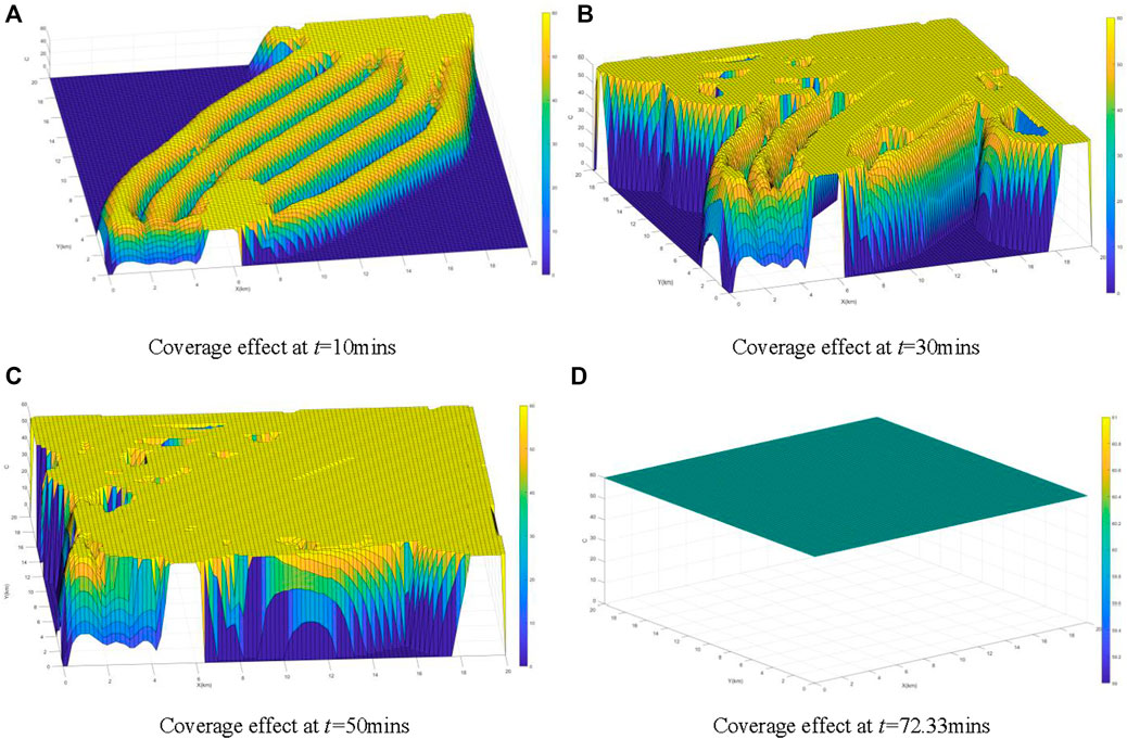
FIGURE 4. Diagram of area coverage at different time.
It can be seen from the trajectory of UAVs at different times in Figure 3 that all UAVs can perform inspection tasks in the task area, and there is no one crossed the border, which shows that the optimal motion direction obtained by the optimization algorithm can effectively restrain the behavior of UAVs and make them move in the direction with the lowest coverage in the sensing area. There are few overlapping areas among UAVs, which shows that the method based on undirected sensing set segmentation can effectively reduce the overlapping of sensing areas among UAVs. It can be seen from Figure 4 that the algorithm can complete the inspection of the whole task area in a limited time, which shows that the algorithm is feasible and effective in controlling the UAVs to complete the inspection task of the designated area. To prove that the method of collision avoidance proposed in this paper is effective, we calculate the minimum distance between any two USVs in the system at any time, and the results are shown in Figure 5. It can be seen from Figure 5 that the minimum distance between any two USVs is more than 0.5 km at any time. So it is obvious that there is no collision between any two USVs and the method proposed in this paper is effective and right.

FIGURE 5. The minimum distance between any two USVs at different time.
When the number of UAVs is
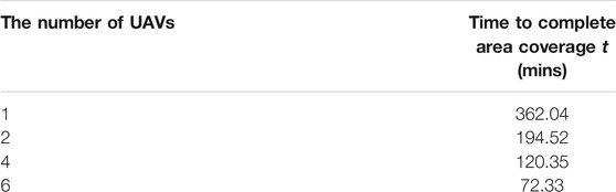
TABLE 2. Time to complete area coverage with different number of UAVs.
Figure 6 shows the time-varying curve of the coverage rate of different numbers of UAVs to the mission area.
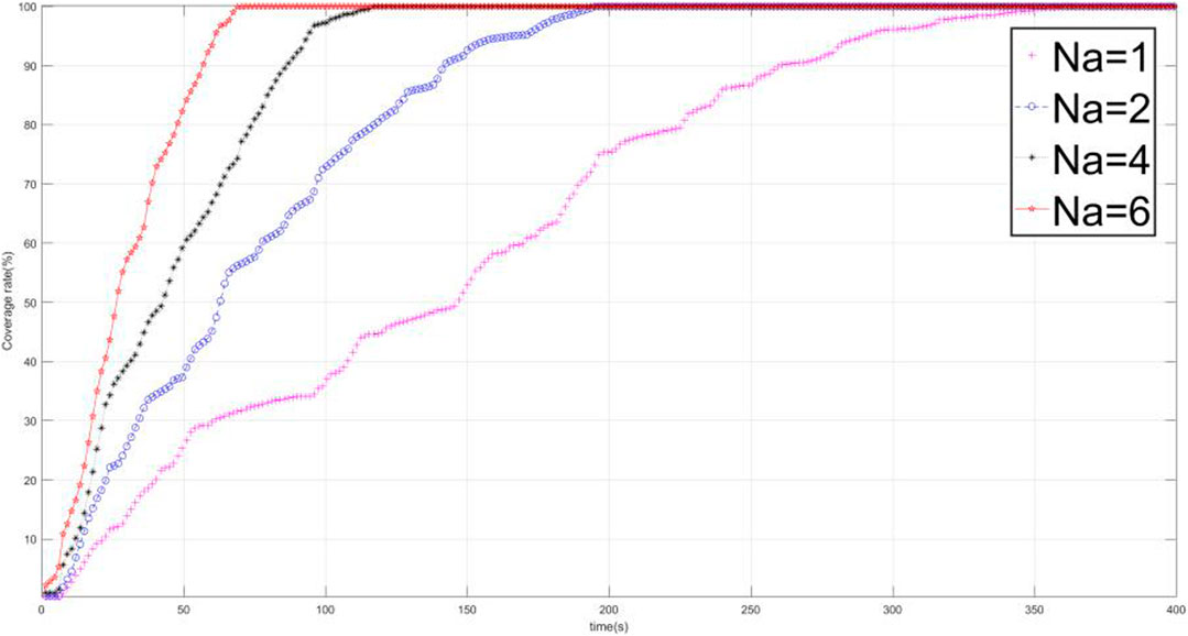
FIGURE 6. The relation between the number of UAVs and the coverage rate of the area.
It can be seen from Table 2 that the time spent by UAVs system is greatly reduced compared with single-UAV inspection, which shows that UAVs inspection system can greatly improve inspection efficiency compared with existing single-UAV inspection methods. It can be seen from Figure 6 that with the increase of the number of UAVs, the area coverage efficiency of UAVs with different numbers increases obviously. This is mainly because the gradient operation of the penalty function is adopted in this algorithm, which makes the movement direction of the UAV choose the area with low coverage preferentially. Therefore, when the number of UAVs increases, the repeated paths of UAVs when performing inspection tasks can be effectively reduced. However, with the increase in the number of UAVs, the phenomenon of path repetition is inevitable. So the inspection efficiency of UAVs system would increase slowly with the increase of the number of UAVs.
Conclusion
Under ideal conditions, this paper studies how UAVs cooperate to improve the efficiency of the inspection task. An optimization algorithm for inspection with UAVs is given, and the feasibility and effectiveness of the algorithm are verified by numerical simulation. In this algorithm, firstly, the overlapping phenomenon of sensing areas of different UAVs is effectively reduced by dividing undirected sensing sets. Secondly, through the gradient operation of the penalty function, the area with the lowest coverage near the UAV is found and designated as the xxmoving direction of the UAV at the next moment, which reduces the repetition rate of the inspection path. The simulation results showed that the coverage efficiency of the UAVs system based on this algorithm increases with the number of UAVs.
To sum up, compared with the existing inspection methods, the UAV autonomous inspection optimization algorithm based on swarm intelligence can greatly improve the inspection efficiency and reduce the cost of inspections. UAV cooperative inspection will become the trend of development in the field of inspection in the future.
Data Availability Statement
The raw data supporting the conclusion of this article will be made available by the authors, without undue reservation.
Author Contributions
YY’s main contribution is to design the algorithm. CJ-h’s main contribution is to analyze the data and the results of experiments. GY’s main contribution is to provide the application background. FZ’s main contribution is to design the motion control law of UAVs. ZA-M’s main contribution is to solve the problem of undirected sensing set segmentation. XB’s main contribution is to obtain the coverage efficiency optimization index in the fixed area. LK’s main contribution is to design the sensing area model of UAV and improve the algorithms.
Funding
This research were funded by the Scientific Research Staring Foundations of Shantou University (No: NTF19028) and (No: NTF20009) and supported by the Natural Science Foundation of Guangdong Province, China (Grant No.2021A1515011709).
Conflict of Interest
The authors declare that the research was conducted in the absence of any commercial or financial relationships that could be construed as a potential conflict of interest.
References
Burciu, Z. (2012). Reliability and Uncertainty in Determining Search Area during Search-And Rescue Action. Polish Maritime Res. 19 (1), 21–30. doi:10.2478/v10012-012-0003-9
Cai, Z. Q. (2020). Research on Path Planning of 220k V Power Line Inspection UAV. Shanxi, China: Taiyuan University of Science and Technology.
Che, M., Savkin, A. V., and Javed, F. (2011). Decentralized Control of a Group of mobile Robots for Deployment in Sweep Coverage. Robotics nd A utonomous Syst. 59 (7), 497–507. doi:10.1016/j.robot.2011.03.001
Cortés, J., Martínez, S., and Bullo, F. (2005). Spatially-distributed Coverage Optimization and Control with Limited-Range Interactions. Esaim: Cocv 11, 691–719. doi:10.1051/cocv:2005024
Dieter, H., and Jennifer, M. (2008). Renewable Energy-The Future for the Developing World. Renew. Energ. Focus 9 (1), 58–61. doi:10.1016/s1471-0846(08)70053-2
Fan, Z., Fang, Y., Li, W., Cai*, X., Wei, C., and Goodman, E. (2019). MOEA/D with Angle-Based Constrained Dominance Principle for Constrained Multi-Objective Optimization Problems. Appl. Soft Comput. 74 (1), 621–633. doi:10.1016/j.asoc.2018.10.027
Jiang, H., Liu, Z., Liu, C., Su, Y., and Zhang*, X. (2020). Community Detection in Complex Networks with an Ambiguous Structure Using central Node Based Link Prediction. Knowledge-Based Syst. 195, 1–13. doi:10.1016/j.knosys.2020.105626
Papatheodorou, S., Tzes, A., and Stergiopoulos, Y. (2016). Collaborative Visual Area Coverage Using Unmanned Aerial Vehicles. arXiv:1612.02065
Poonam, S., Manjaree, P., and Laxmi, S. (2020). Comparison of Traditional and Swarm Intelligence Based Techniques for Optimization of Hybrid Renewable Energy System. Renew. Energ. Focus 35 (12), 1–9. doi:10.1016/j.ref.2020.06.010
Stone, L. D., Keller, C. M., and Kratzke, T. M. (2014). Search for the Wreckage of Air France Flight AF 447. Stat. Sci. 29 (1), 69–80. doi:10.1214/13-sts420
Tian, Y., Lu, C., Zhang*, X., Tan, K. C., and Jin, Y. (2020a). Solving Large-Scale Multi-Objective Optimization Problems with Sparse Optimal Solutions via Unsupervised Neural Networks. IEEE Trans. Cybernetics. in press.
Tian, Y., Zhang, T., Xiao, J., Zhang*, X., and Jin, Y. (2020b). A Coevolutionary Framework for Constrained Multi-Objective Optimization Problems. IEEE Trans. Evol. Comput. in press.
Wang, C., Xu, R., Qiu, J., and Zhang, X. (2020). AdaBoost-inspired Multi-Operator Ensemble Strategy for Multi-Objective Evolutionary Algorithms. Neurocomputing 384, 243–255. doi:10.1016/j.neucom.2019.12.048
Xiang, X., Qiu, J., Xiao, J., and Zhang*, X. (2020). Demand Coverage Diversity Based Ant colony Optimization for Dynamic Vehicle Routing Problems. Eng. Appl. Artif. Intelligence. in press.
Yin, B. H. (2016). High Voltage Distribution Network Visual Inspection System Based on Unmanned Aerial Vehicle (Uav) Research. Guangzhou, China: Guangdong University of Technology.
Zhang, X., Tan, T., Zhou, B., Yu, T., Yang, B., and Huang, X. (2021). Adaptive Distributed Auction-Based Algorithm for Optimal Mileage Based AGC Dispatch with High Participation of Renewable Energy. Int. J. Electr. Power Energ. Syst. 124, 106371. doi:10.1016/j.ijepes.2020.106371
Zhang, X., Xu, Z., Yu, T., Yang, B., and Wang, H. (2020). Optimal Mileage Based AGC Dispatch of a GenCo. IEEE Trans. Power Syst. 35 (4), 2516–2526. doi:10.1109/tpwrs.2020.2966509
Zhou, Z. G., Zhou, H., Hu, B., et al. (2018). Application and Prospect of UAV in Power Line Inspection. Scientific Technol. innovation (23), 164–165. doi:10.3390/rs9080824
Zou, A. M., and Fan, Z. (2020). Distributed Fixed‐time Attitude Coordination Control for Multiple Rigid Spacecraft. Int. J. Robust Nonlinear Control. 30 (1), 266–281. doi:10.1002/rnc.4763
Zou, A. M., and Li, W. (2019). Fixed‐time Output‐feedback Consensus Tracking Control for Second‐order Multiagent Systems. Int. J. Robust Nonlinear Control. 29 (13), 4419–4434. doi:10.1002/rnc.4633
Keywords: renewable energy, power grid, autonomous inspection, swarm intelligence, area coverage
Citation: Yao Y, Jun-hua C, Yi G, Zhun F, An-Min Z, Biao X and Ke L (2021) Autonomous Control Method of Rotor UAVs for Power Inspection With Renewable Energy Based on Swarm Intelligence. Front. Energy Res. 9:697054. doi: 10.3389/fenrg.2021.697054
Received: 18 April 2021; Accepted: 03 May 2021;
Published: 22 June 2021.
Edited by:
Yaxing Ren, University of Warwick, United KingdomReviewed by:
Xinxin Xie, Sun Yat-sen University, ChinaDandan Liu, Yancheng Institute of Technology, China
Copyright © 2021 Yao, Jun-hua, Yi, Zhun, An-Min, Biao and Ke. This is an open-access article distributed under the terms of the Creative Commons Attribution License (CC BY). The use, distribution or reproduction in other forums is permitted, provided the original author(s) and the copyright owner(s) are credited and that the original publication in this journal is cited, in accordance with accepted academic practice. No use, distribution or reproduction is permitted which does not comply with these terms.
*Correspondence: Li Ke, ZXJpY2xlZUBzdHUuZWR1LmNu