 Chao Guo1
 Pengcheng Zhao
94% of researchers rate our articles as excellent or good
Learn more about the work of our research integrity team to safeguard the quality of each article we publish.
Find out more
ORIGINAL RESEARCH article
Front. Energy Res., 08 June 2021
Sec. Nuclear Energy
Volume 9 - 2021 | https://doi.org/10.3389/fenrg.2021.678939
SNCLFR-100 is a small modular natural circulation lead-cooled fast reactor, developed by University of Science and Technology of China, aiming at taking full advantage of the good economics and inherent safety of lead-cooled fast reactors to develop miniaturized, lightweight and multi-purpose special nuclear reactor technology. SNCLFR-100 is still in the conceptual design stage, in order to fully evaluate the safety features of the reactor and provide reference for the optimization design of the next stage, three typical transients are selected based on the analysis of the SNCLFR-100 initiating events by using the code Analysis of Thermal-hydraulics of Leaks and Transients (ATHLET), which are unprotected transient overpower (UTOP), unprotected loss of heat sink (ULOHS) and unprotected partial blockage in the hottest fuel assembly. For UTOP, the unexpected positive reactivity insertion of 0.7$ in 15s led to two large power peaks in the core quickly, and then the core power began to decrease and gradually stabilized under the action of various of negative feedbacks of the reactor, the peak temperatures of fuel and cladding rose rapidly with the increase of core power and eventually stabilized at a higher temperature. For ULOHS, as the reactor were driven by natural circulation, the coolant mass flow rate continued to decline after the transient, both core and cladding temperatures rose quickly and the temperature rise were smaller than that of UTOP transient, the reactor shutdown by itself and the peak temperatures of fuel and cladding were smaller than the safety limit. For unprotected partial blockage in the hottest fuel assembly, with the increase of the blockage rate of the hottest fuel assembly inlet, the coolant flow rate, the peak temperatures of coolant, fuel and cladding increased significantly, when the blockage rate increased to 0.9, the coolant flow rate of the hottest fuel assembly dropped to about 12.6% of the normal value, and the cladding peak temperature would exceed the cladding melting point, measures should be taken to avoid the happening of severe accident.
The Lead-cooled Fast Reactor (LFR) is one of the innovative systems envisaged by the Generation IV International Forum (GIF) in order to provide sustainable, safe and proliferation resistant nuclear energy production (Lorusso et al., 2018; Zhang et al., 2019). In the Generation IV technology evaluations, the LFR was rated good in safety and economics and have been evaluated as the most promising technology, which was primarily envisioned for missions in electricity, hydrogen production and actinide management (Kelly, 2014; Liu et al., 2020). In recent years, with the development of anticorrosion technology and 210Po purification technology, LFR was identified as a technology with great potential to meet needs for remote sites power stations, industrial heating, nuclear hydrogen production, combined heat and power supply, seawater desalination and ship propulsion, and has attracted wide attention around the world (Alemberti et al., 2014; Mignacca and Locatelli, 2020). In Russia, an innovative inherent-safe fast reactor named BREST-OD-300, is being developed as a pilot and demonstration prototype for future nuclear power with a closed nuclear cycle, and are scheduled to be finished in 2023 (Dragunov et al., 2012). In addition, a small scale modular LBE-cooled fast reactor SVBR is being built based on Russia’s rich experience in liquid metal cooled fast reactor construction and operation (Zrodnikov et al., 2011). In Europe, the development of lead-cooled fast reactor technology is very active with the support of PDX-ADS project, LEADER project and CDT project, etc. a European Lead-cooled Fast Reactor (ELFR) (Frogheri et al., 2013), an Advanced Lead-cooled Fast Reactor European Demonstrator (ALFRED) and a Multi-purpose hybrid Research for High-tech Applications (MYRRHA) were currently being developed (Grasso et al., 2014; Engelen et al., 2015). In China, a 10 MWth lead-based research reactor named China Lead-based Reactor (CLEAR-I), proposed by the Institute of Nuclear Energy Safety Technology, was selected as the reference reactor for ADS development, as well as the technology development of the Generation IV lead-cooled fast reactor (Smith et al., 2008). Due to the outstanding natural circulation characteristics of lead-bismuth (LBE) and lead, many natural circulation LFR have been developed. In United States, A series of natural circulation LFR conceptual design were carried out by Argonne National Laboratory (ANL) and Lawrence Livermore National Laboratory (LLNL), such as SSTAR (Bortot et al., 2011), SUPERSTAR (Koo et al., 2007), STAR-LM (Hong et al., 2005), and ENHS (Wu, 2016). In China, a 100 MWth lead-cooled small modular reactor named SNCLFR-100 with a passive cooling feature to both normal and abnormal operations, was proposed by University of Science and Technology of China (USTC) (Chen et al., 2016; Zhao et al., 2016).
For natural circulation LFRs, the outstanding inherent safety performance can greatly reduce the construction and operation difficulty of LFR, and provide a good technical route for the engineering and commercialization of LFR as soon as possible. However, compared with forced circulation, the natural circulation lead-cooled fast reactor has a weaker coolant circulation capacity, transient safety analysis is an important part of LFR design and operation, it can be seen from the open literature that the current transient analysis of lead-cooled fast reactors (LFRs) is mainly aimed at forced circulation LFRs, while the research on the transient thermal-hydraulic safety performance of natural-cycle lead-cooled fast reactors has many deficiencies (Tesinsky et al., 2012; Bubelis et al., 2013; Castelliti and Hamidouche, 2016; Shen et al., 2019). Thus, it is necessary to analyzed the transient response characteristics of natural circulation LFR and evaluate the thermal-hydraulic safety performance of the reactor to further optimize the design of this kind of reactor, which is of great significance to further promote its development.
For SNCLFR-100, a total of six transients were selected as representative of all identified design extension condition (DEC) transients reflecting a wide range of potential transient initiators using the main logic diagram method (MLD) (Kangli, 2017), these transients include several unprotected transients such as UTOP, ULOHS etc. To investigate the safety behaviors of SNCLFR-100, unprotected transient overpower (UTOP), unprotected loss of heat sink (ULOHS) and unprotected partial blockage in the hottest fuel assembly were selected and analyzed using the advanced best-estimate code ATHLET 3.1A, which enables the simulation of liquid metal cooled fast reactor (Hollands et al., 2019).
SNCLFR-100 uses pure melted lead as primary coolant by means of natural circulation, the rated thermal power of SNCLFR-100 is 100 MW and the refueling interval is 10 years without assembly reconfiguration. SNCLFR-100 is a typical pool-type reactor with an array of heterogeneous square fuel assemblies loaded with MOX fuels (Zhao et al., 2016; Shi et al., 2018). The overall structure design of SNCLFR-100 primary cooling system and fuel assembly are shown in Figure 1, and the main design parameters are listed in Table 1. The fuel assembly shown in Figure 4 is a 9 × 9 pins lattice. The pitch-to-diameter ratio is 1.426 and the assembly pitch is 160.0 mm. The wide coolant paths among rods can reduce the pressure drop significantly and enhance the reactor natural circulation capability.
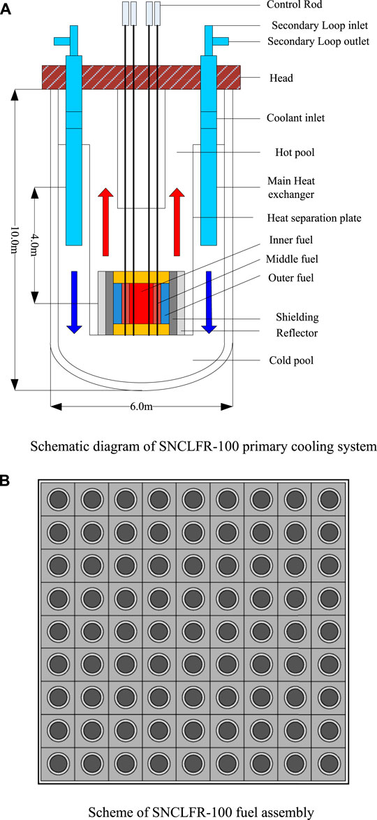
FIGURE 1. Scheme of SNCLFR-100 primary cooling system and fuel assembly. (A) Schematic diagram of SNCLFR-100 primary cooling system. (B) Scheme of SNCLFR-100 fuel assembly.
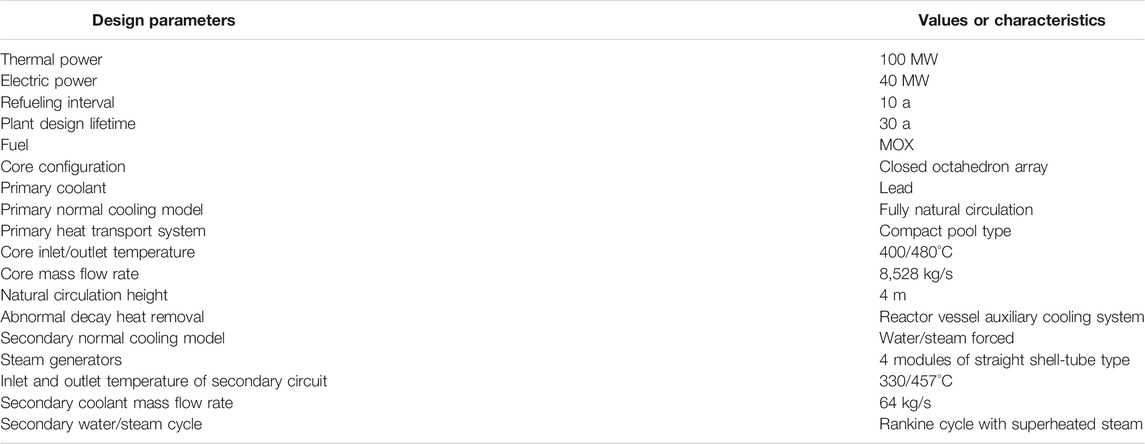
TABLE 1. Main design parameters of SNCLFR-100.
The SNCLFR-100 primary cooling system mainly consists of a cold pool, a reactor core, a hot pool, a main heat exchanger, a heat separation plate and a main vessel. Liquid lead enters the reactor core from the cold pool, cools the reactor core from bottom to top under natural circulation driving force, absorbs the heat of each assembly of the reactor core and then flows into the hot pool. After being fully mixed, it flows into the shell side of the main heat exchanger, transfers the heat to the secondary coolant on the tube side, flows out of the main heat exchanger, and flows back into the cold pool. Thus, the coolant circulation of the primary circuit is formed. Figure 2 is the layout of SNCLFR-100 core, and Table 2 gives the main design parameters of the core. The fuel assemblies of SNCLFR-100 core are designed like boxes. The active area consists of 204 fuel assemblies. According to the enrichment, the active core is divided into inner, middle and outer regions. 36 control assemblies, 48 reflector assemblies and 84 shielding layer assemblies are respectively arranged radially outward of the reactor core.
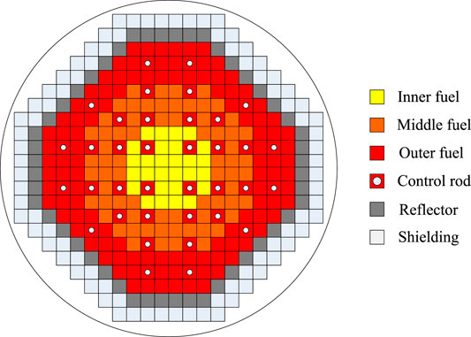
FIGURE 2. SNCLFR-100 core layout.
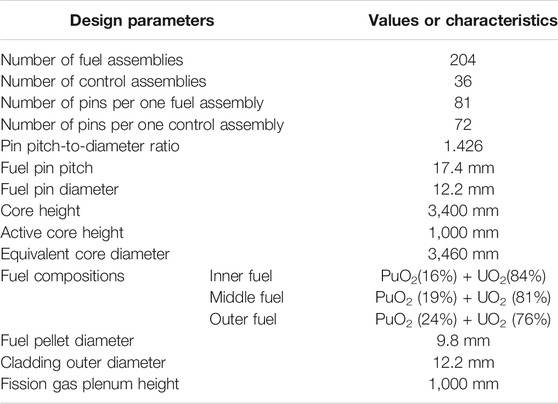
TABLE 2. SNCLFR-100 core main design parameters.
ATHLET is an analytical code for the optimal thermohydraulic estimation system of light water reactors developed by the GRS. After years of development and improvement by GRS, the analysis accuracy and reliability have been continuously improved, and the application scope has been continuously widened. The code has become one of the internationally recognized important tools for thermal and hydraulic analysis and safety assessment of nuclear power plants. At present, the latest ATHLET MOD3.1A released by GRS has been used to simulate and analyze the thermal-hydraulic safety characteristics of lead-cooled fast reactor, sodium-cooled fast reactor and supercritical water-cooled reactor (Lerchl et al., 2016).
Figure 3 shows the ATHLET calculation model of the primary cooling system of SNCLFR-100. The model includes the main equipment and fuel assembly of the primary cooling system of SNCLFR-100. Considering that SNCLFR-100 is a natural circulation reactor and the operation state of the secondary circuit will have an important influence on the thermal hydraulic characteristics of the primary circuit, the secondary cooling system of SNCLFR-100 is appropriately simplified in the calculation model and only the tube-side heat exchange part of the secondary cooling system is considered. Feedwater is supplied by a Fill, which exiting steam pressure is fixed by a TDV, and the corresponding inlet and outlet boundary conditions are reasonably set. According to the structural layout of the SNCLFR-100 core shown in Figure 2, the calculation model divides the cooling channel of the core into eight channels. Each fuel assembly zone and control rod assembly zone are simulated with an average channel and a thermal channel, respectively. Average channels in inner fuel zone, middle fuel zone, outer fuel zone and control rod assembly zone (FI_Ave, FM_Ave, FO_Ave, and Cr _ ave); Hot channel in the inner fuel zone, the middle fuel zone, the outer fuel zone, and the control rod assembly zone (FI_Hot, FM_Hot, FO_Hot, and CR_Hot). At the same time, according to the neutron calculation results, the average rod and the hottest rod are respectively considered in the above four thermal channels.
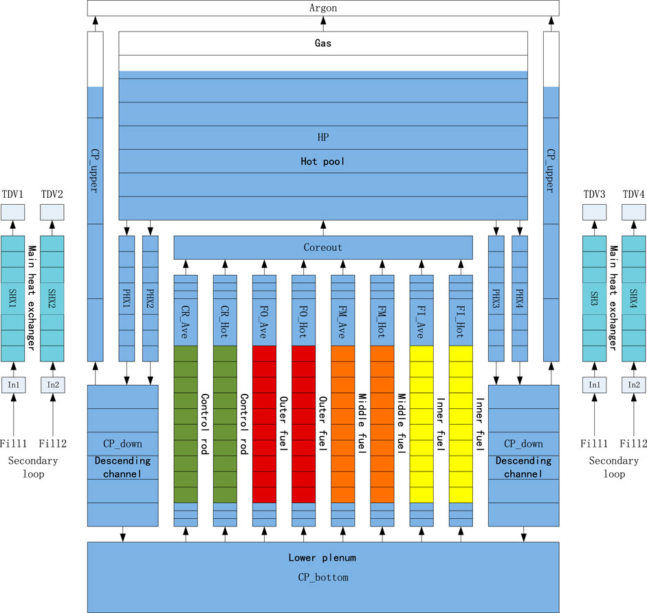
FIGURE 3. Calculation model of SNCLFR-100 primary cooling system.
In order to meet the development goals and requirements for the fourth generation nuclear power system, the lead-cooled fast reactor has adopted a large number of innovative design concepts, which not only makes the reactor have good economy and inherent safety, but also brings great challenges to the thermal hydraulic design and safety analysis of the reactor. Therefore, no mature and reliable thermal hydraulic design and safety criteria for lead-cooled fast reactors have been put forward by the nuclear energy industry. The thermal-hydraulic safety criteria adopted in the design schemes of lead-cooled fast reactors currently designed by various countries are different (Cinotti et al., 2010; Alemberti et al., 2017). Based on the design characteristics of natural circulation lead-cooled fast reactors, through full investigation and reference to the thermal-hydraulic safety criteria adopted in the design of internationally representative lead-cooled fast reactors, the following thermal-hydraulic safety criteria applicable to SNCLFR-100 are proposed:
(1) The velocity of LBE determines the corrosion of LBE on structural materials. As a result, the limit of coolant velocity is set to 2 m/s to protect the structural material from corrosion. Therefore, the coolant velocity limit of SNCLFR-100 is set to 2 m/s;
(2) To ensure that the solidification of Lead does not happen in the reactor, 350°C is selected as the minimum temperature limit for the coolant, which is higher than the LBE melting point temperature of 327.46°C;
(3) MOX is selected as the fuel in SNCLFR-100. It is necessary to ensure that fuels are not threatened under all operating conditions. According to the physical parameters of MOX and design limits of SNCLFR-100, the limit of the peak fuel centerline temperature is 2,300°C;
(4) T91 is employed for cladding material, which has shown its significant corrosion resistance and excellent mechanical advantages. Jinsuo Zhang investigated the steel corrosion by liquid lead and LBE, which demonstrated that T91 could meet the performance requirements under the condition of 823 K (Zhang, 2009). As a result, the SNCLFR-100 set the limits of the peak cladding surface temperature conservatively to 550°C under steady state. In transients, the value is designed to 650°C to ensure the integrity of fuel cladding. At the same time, it is considered acceptable for the cladding temperature to temporarily exceed 800°C in case of severe accidents.
Steady state condition calculation is the basis for transient thermal-hydraulic safety analysis. The steady state characteristics of SNCLFR-100 under rated conditions are studied by ATHLET. Table 3 shows the comparison between the main thermal hydraulic parameters of the primary cooling system calculated by ATHLET and the design values of the reactor. From Table 3, it can be seen that the calculation results of ATHLET code are in good agreement with the design values of SNCLFR-100, indicating that the primary cooling system of the reactor is correctly modeled. It can be used for transient analysis of accident conditions.
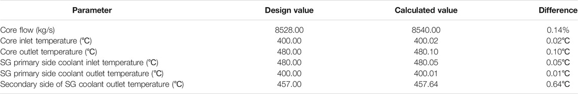
TABLE 3. Steady state calculation results under rated conditions.
This transient is initiated by an unexpected positive reactivity insertion of 0.7 $ (257.6 pcm) in 15 s following possible perturbations in the primary cooling system induced by steam generator tube rupture (SGTR), FA flow blockage or core compaction, etc. The transient is unprotected and then the reactor scram is assumed to fail, which forced circulation is maintained in the secondary circuits with no control of the feedwater flow rate, which remains constant at its nominal value.
SNCLFR-100 overpower transient at HFP (Hot Full Power) and BOC, namely:
(1) Between 0 and 500 s, the reactor operates in rated condition.
(2) At 500 s, the control rod is withdrawn at a maximum moving speed of 300 mm/s, and 0.7 $ (257.6 pcm) reactivity is introduced into the core within 15 s.
Figures 4, 5, respectively, show the changes of reactor power and reactivity with time after the UTOP accident of SNCLFR-100. As can be seen from Figures 4, 5, after the accident, the core power increased rapidly and two peaks appeared successively: the first peak appeared at about 515 s, and the core power was about 3.85 times of the rated power. At this time, the control rod was completely withdrawn out of control, and the total reactivity of the core and instantaneous neutrons reached the maximum value. The second peak occurred at about 552 s, at which time the core power peaked again (about 3.45 times of the rated power) under the action of delayed neutrons accumulated in the core. After the accident occurred 500 s, the reactor power gradually stabilized, reaching a new balance at about 1,200 s and operating at a relatively high power.
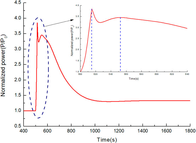
FIGURE 4. Reactor power vs. time at UTOP.
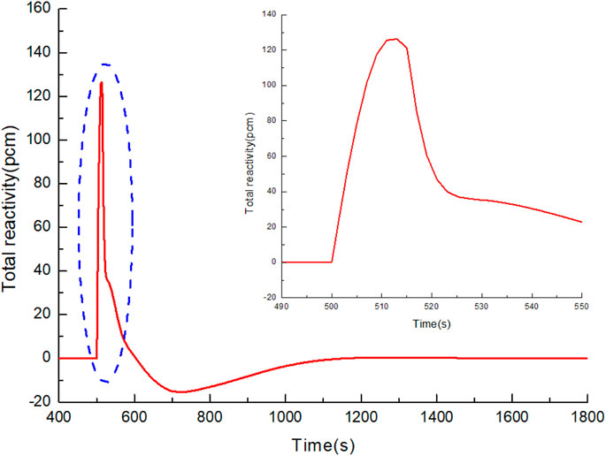
FIGURE 5. Reactor reactivity vs. time at UTOP.
The change of core flow with time after the UTOP accident of SNCLFR-100 is shown in Figure 6. It can be seen form Figure 6, when UTOP accident occurs, the coolant flow rate through the core increases rapidly with the increase of the core power and reaches a peak value at about 548 s s. After that, it decreased continuously with the continuous attenuation of reactor power, and finally stabilized at about 1,200 s. It is noted in the analysis that, unlike the forced circulation lead-cooled fast reactor, the natural circulation lead-cooled fast reactor has a unique consequence of the accident and also reflects the unique inherent safety performance of the natural circulation lead-cooled fast reactor. As the core power increases, the core flow rate and the core heat transfer capacity increases, and the natural circulation capacity increases.
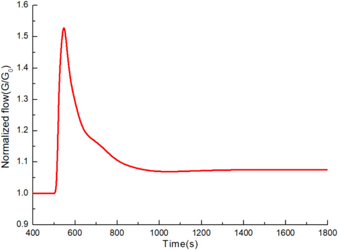
FIGURE 6. Core mass flow rate vs. time at UTOP.
Hottest fuel pellet temperatures and hottest cladding temperature with time under UTOP accident are shown in Figures 7, 8. The simulation results show that, during the transients, fuel pellet temperature and cladding temperature rapidly increased. Two temperature peaks appeared corresponding to the power change, and the highest temperature peaks appeared in the outer fuel region at 500 s. The fuel pellet and cladding temperature gradually stabilized and remained basically unchanged at about 1,200 s. During the whole accident process, the highest fuel and cladding temperature are both lower than the safety limit. However, the cladding will be operated at a higher temperature for a long time, and the safety margin of the reactor is small, which is harmful to the long-term operation of the reactor. Effective measures need to be taken to increase the heat transfer capacity of the primary loop main cooling system and reduce the operating temperature of the system.
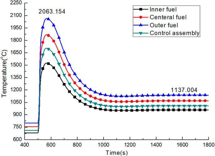
FIGURE 7. Hottest fuel pellet temperatures for the hot channels vs. time at UTOP.
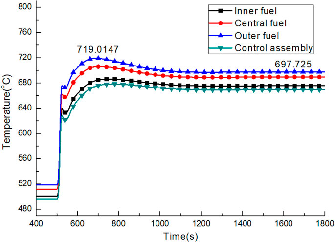
FIGURE 8. Time evolution of hottest pin cladding temperatures for the hot channels at UTOP.
The ULOHS transient initiates form a total loss of feedwater flow into the secondary side of SG, leaving decay heat removal system working to remove heat form core. The reactor scram is assumed to fail and then the core power is driven by the reactivity feedbacks, natural circulation is maintained in the primary system, while the secondary circuits are isolated.
SNCLFR-100 ULOHS transient at HFP (Hot Full Power) and BOC, namely:
(1) Between 0 s and 500 s, the reactor operates normally under rated conditions.
(2) At 500 s, all feedwater pumps in the secondary loop of the reactor were shut down due to faults, and the flow rate of the secondary loop cooling system decreased rapidly. After the accident, the flowrate of feedwater decreased to 50% of the rated flow rate within 5 s and decreased to 0 kg/s at 46 s.
The change of core flow with time after the ULOHS accident in SNCLFR-100 is shown in Figure 9. When the accident occurred, the core flow rate decreased rapidly and reached the lowest value at 900 s. Between 900 s and 2,300 s after the accident, the core flow slowly increases. At 2,300 s after the accident, the core flow gradually stabilized and finally stabilized at about 16.2% of the rated flow. It is noted that, unlike the driving cycle lead-cooled fast reactor, the ULOHS accident of the natural circulation lead-cooled fast reactor will indirectly cause the loss of flow of primary loop and lead to core temperature rise.
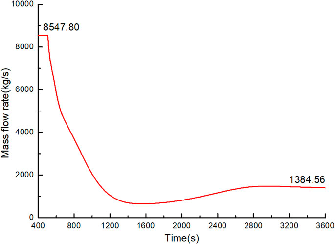
FIGURE 9. Core mass flow rate vs. time at ULOHS.
The variation of reactor power vs. time after the ULOHS accident in SNCLFR-100 is shown in Figure 10. After the accident, the core power rapidly dropped to about 18 MW at 400 s. At this time, the reactor was automatically shut down by negative feedback effects. The fission power of the reactor is nearly reduced to 0 MW at 2,300 s, and the total power comes from the decay heat in the reactor.
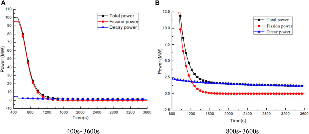
FIGURE 10. Reactor power vs. time at ULOHS. (A) 400 ∼ 3600 s (B) 800 ∼ 3600 s.
The variation of the maximum temperature of the fuel pellet and cladding of the hottest assembly with time after the ULOHS accident is shown in Figures 11, 12. During the accident, the temperature of the fuel pellets decreased rapidly with the attenuation of the core power, and gradually stabilized around 1,200 s. At the beginning of the accident, the descent rate of core power is greater than that of core flow. The highest temperature of the cladding firstly increases and reaches the peak value. Then, the highest temperature of the cladding gradually falls and reaches the steady state, and finally keeps a small rise momentum. It can be seen from the analysis that with the development of ULOHS accident, the temperature difference between the fuel and the cladding becomes smaller and smaller, and the temperature distribution of the core will become more uniform. During the whole accident, the temperatures of the fuel and the cladding are far lower than the design limit, and the reactor has sufficient safety margin.
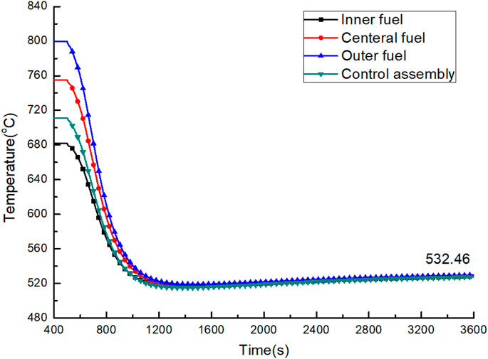
FIGURE 11. Hottest pin fuel pellet temperatures for the hot channels vs. time at ULOHS.
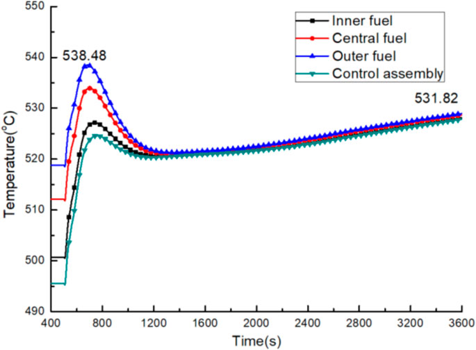
FIGURE 12. Time evolution of hottest cladding temperatures for the hot channels at ULOHS.
Parametric studies on partial blockage in the hottest fuel assembly has been investigated in the unprotected case without reactor scram, in order to evaluate the maximum reduction of cross flow rate or flow rate through the assembly that might be sustained without leading to significant fuel rod damage (Chai et al., 2019; Chai et al., 2020). In general, conservative assumptions have been taken with respect to heat transfer through the inter-wrapper gap with the surrounding assemblies.
The unprotected partial blockage in the hottest fuel assembly is as follows:
(1) Partial blockage of the hottest fuel assembly, assembly inlet assumed to be blocked.
(2) Blockage is defined by a decrease of flow area, with constant loss factor.
(3) It is assumed that at 500 s, the corrosion products of the core block the inlet of the hottest-assembly within 1 s, resulting in a decrease of coolant flow through the assembly and an increase of coolant temperature in the assembly. During this process, the reactor protection system failed and no shutdown protection measures were taken. At the same time, we define a parameter which is blocking rate (namely: β).A
Where,
(4) Blockage fractions: 10, 20, 30, 40, 50, 60, 70, 80, 90%.
(5) Reactor trip (SCRAM signal) is disabled. No heat exchange with surrounding assemblies.
The blockage rate of the hottest assembly inlet will directly affect the severity of the consequences of the blockage accident. This paper simulates the local blockage conditions of the hottest assembly under nine different blockage rates to analyze the impact of the increase of blockage rate on the blockage accident. Figure 13 shows the variation of core power with time under different blocking rates. It can be seen that the blockage of the hottest assembly has little influence on the core power. With various reactivity feedbacks, the core power decreases rapidly and slightly, then gradually increases, and finally stabilizes at a state slightly lower than the rated power. With the increase of the core inlet blockage rate, the larger blockage rate leads to the smaller the final steady-state power.
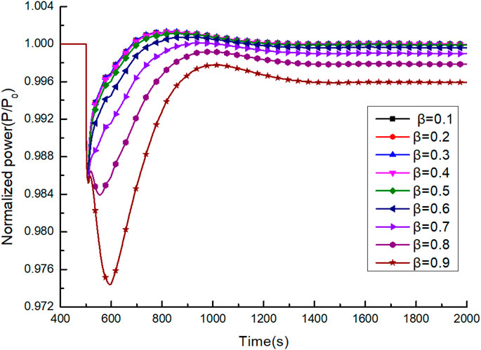
FIGURE 13. The influence of different blockage rates on total core power vs. time.
Figure 14 shows the influence of different blockage rates on the flow rate of the hottest assembly of SNCLFR-100 after the local blockage accident. As can be seen from Figure 14, when a local flow blockage occurs, the flow rate of the hottest assembly drops rapidly to a minimum value at first, then gradually rise, and finally gradually stabilize around 600 s. When the blockage rate is less than 0.3, the blockage accident has little effect on the flow rate of the hottest assembly. When the blockage rate is greater than 0.3, the flow rate of the hottest assembly decreases rapidly with the increase of the blocking rate. When the blocking rate reaches about 0.6, the flow rate in the hottest assembly will be about 50% of the rated flow rate. When the blockage rate reaches 0.9, its flow is about 12.6% of the rated flow.
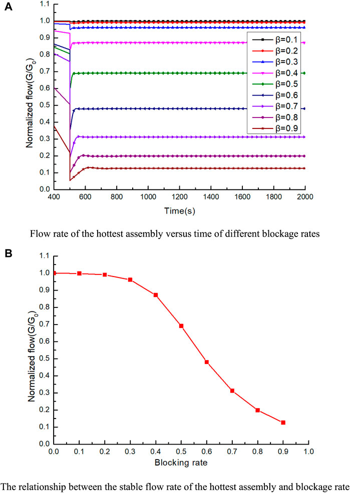
FIGURE 14. Influence Curve of Different Blockage Rates on Flow Rate of hottest assembly. (A) Flow rate of the hottest assembly vs. time of different blockage rates. (B) The relationship between the stable flow rate of the hottest assembly and blockage rate.
Figure 15. shows the changes of power and flow of the hottest assembly vs. time under different blockage rates. When the blocking rate is small, drop amplitude and drop rate of core power of the hottest assembly are both greater than the corresponding value of its flowrate. However, when the blocking rate is large, the drop amplitude and rate of flowrate are much larger than the corresponding power value. At the same time, it is noted that when the power and flowrate of the hottest assembly reach a stable level, its power can eventually return to the rated value. When the blockage rate is small, its flowrate will be slightly lower than the rated value. The flowrate will be far lower than the rated value when the blockage rate is large.
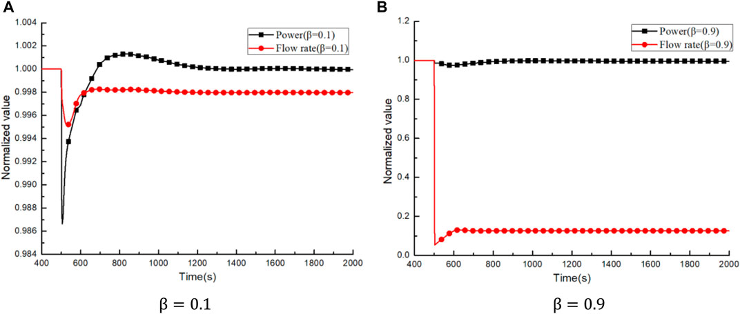
FIGURE 15. Comparison of power and flow of hottest assembly vs. time of different blocking rates. (A) β = 0.01 (B) β = 0.09.
Figure 16 shows the variation of the maximum temperature at the center of fuel pellet of the hottest assembly after the local blockage occurred in SNCLFR-100. Due to the power ascending of the hottest assembly and the descending of the flow rate, the highest fuel temperature ascends and reaches a peak value. Finally, with the gradual stabilization of the power and flow rate of the hottest assembly, the highest fuel temperature begins to drop and gradually stabilizes. The larger the blockage rate is, the smaller the drop in the center temperature of fuel pellet of the hottest assembly is, and the larger the final temperature peak is. When the blocking rate reaches 0.9, the highest temperature in the center of fuel pellet reaches about 1,486.06°C, which is lower than the temperature safety limit of 2,300°C.
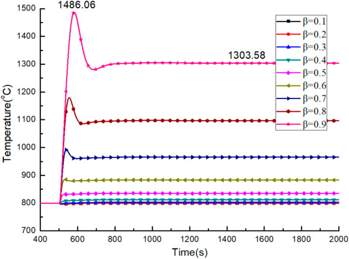
FIGURE 16. The maximum temperature of the hottest pin fuel center of different blocking rates vs. time.
Figure 17 shows the change of coolant outlet temperature of the hottest assembly with time after the local blockage accident. It can be seen from Figure 17 that due to the lack of cooling capacity, the outlet of the hottest assembly turned upward and reached the peak value. Finally, with the gradual stabilization of the power and flow rate of the hottest assembly, the temperature of the coolant at the assembly outlet turns to drop and gradually stabilizes. With the increase of blockage rate, the temperature drop amplitude at the outlet of the assembly gradually decreases, and the final coolant temperature peak value gradually increases. When the blocking rate reaches 0.9, the coolant peak temperature is about 1,286°C, which is lower than the boiling point temperature of liquid lead.
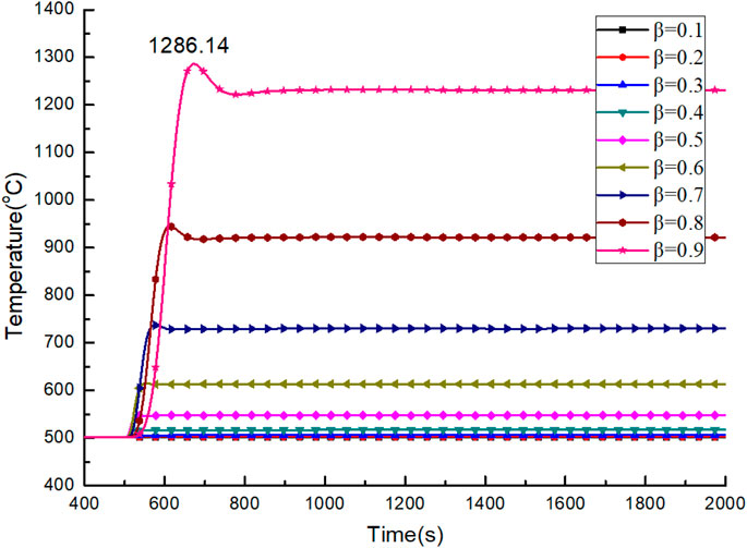
FIGURE 17. The outlet temperature of hottest assembly of different blocking rates vs. time.
Figure 18 shows the variation of the highest cladding temperature of the hottest assembly with time after the local blockage accident. It can be seen from Figure 18 that the highest cladding temperature of the hottest assembly and the outlet coolant temperature of the hottest assembly have similar variation trends. With the increasing blocking rate, the highest cladding temperature ascends rapidly. When the blocking rate reaches 0.9, the highest cladding temperature reaches about 1,407.02°C, exceeding the melting point of the cladding 1,400°C. At this time, the cladding will melt in the hottest assembly.
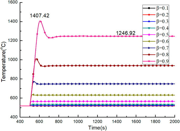
FIGURE 18. The maximum cladding temperature of the hottest assembly of different blocking rates vs. time.
Figure 19 shows the comparison of the hottest pin fuel center temperature, the hottest pin cladding temperature, the hottest channel coolant outlet temperature of different blockage rates after the local blockage accident occurred in SNCLFR-100. As can be seen from Figure 19, when the blocking rate is greater than 0.6, the highest cladding temperature will be greater than 650°C. When the blockage rate reaches about 0.7, the highest cladding temperature will reach 800°C. When the blockage rate reaches 0.9, the highest cladding temperature will exceed the cladding melting point 1,400°C. At this time, the center temperature of the fuel pellet and the coolant temperature are both lower than the safety limit. It can be seen from this that the greatest danger to the core safety in the flow blocking accident comes from the failure of the cladding material at high temperature.
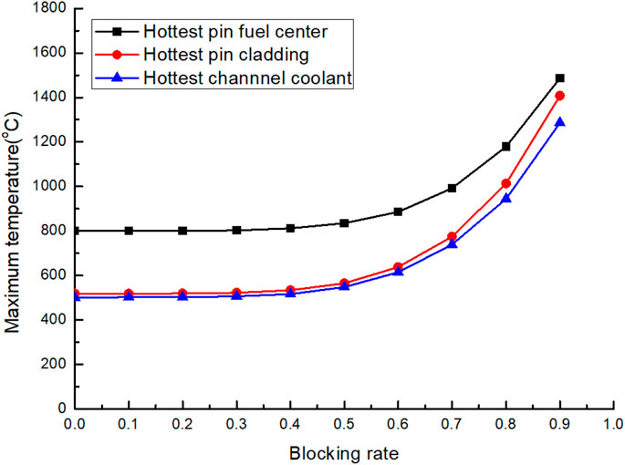
FIGURE 19. The hottest pin fuel center temperature, hottest pin cladding temperature, hottest channel coolant outlet temperature of different blockage rates vs. time.
In this paper, based on the system analysis code ATHLET, three types of unprotected accident transients of SNCLFR-100 are simulated and analyzed, and safety assessment is carried out. The main conclusions are as follows:
(1) In the UTOP transient, the maximum temperatures of fuel core and cladding are all within the safety design limits, but the thermal-hydraulic safety margin of reactor is small, and cladding damage may be induced if the cladding is operated in a high temperature environment for a long time. In the UTOP accident of the natural circulation lead-cooled fast reactor, as the core power increases, the core flow rate and the core heat transfer capacity increases, and the natural circulation capacity increases which is helpful to mitigate the consequences of UTOP accident
(2) In the ULOHS transient, the reactor will automatically shut down under the action of various negative feedbacks in the core. The ULOHS accident of the natural circulation lead-cooled fast reactor will indirectly cause the loss of flow of primary loop and lead to core temperature rise. During the whole transient process, the reactor has a large safety margin. Among the three typical unprotected transient conditions analyzed, the reactor has the highest safety margin.
The above analysis shows that SNCLFR-100 has excellent inherent safety performance for the analyzed unprotected transient conditions. The full natural circulation design can further effectively improve the safety performance of the lead-cooled fast reactor. Under accident conditions, the biggest problem threatening the safety of the core is that the cladding material cannot withstand higher temperature.
(3) In the Unprotected partial blockage in the hottest fuel assembly transient, with the increasing blockage rate at the inlet of the hottest assembly, the variation amplitude of the core power is small. The flow rate of the hottest assembly, the highest fuel temperature, the highest cladding temperature and the coolant outlet temperature change obviously. When the blockage rate reaches 0.6, the flow rate of the hottest assembly will be about 50% of the rated flow rate, while the highest temperature of the hottest rod cladding will reach 650°C. When the blocking rate reaches 0.9, the flow rate of the hottest assembly will drop to about 12.6% of the rated flow rate, and the highest temperature of the cladding will exceed the melting point of the cladding material by 1,400°C.
The raw data supporting the conclusions of this article will be made available by the authors, without undue reservation.
CG: acquisition of data. PZ: Conception and design of study. JD: Conception and design of study. HY: analysis and interpretation of data.
The authors declare that the research was conducted in the absence of any commercial or financial relationships that could be construed as a potential conflict of interest.
The corresponding authors wish to thank GRS for providing the ATHLET code, and the colleagues at University of Science and Technology of China, School of Nuclear Science and Technology for their many valuable helps, especially Prof. Hongli Chen for her selfless supporting.
Alemberti, A., Frogheri, M. L., Hermsmeyer, S., Smirnov, L. A., Takahashi, M., Smith, C., et al. (2014). Lead-cooled Fast Reactor (LFR) Risk and Safety Assessment White Paper[C]. GEN. IV Int. Forum.
Alemberti, A., Tuček, K., Takahashi, M., Obara, T., Moiseev, A., Tocheny, L., et al. (2017). “Development of Safety Design Criteria for the lead‐cooled Fast Reactor,”.in International conference on fast reactors and related fuel cycles (FR17). 26–29 June 2017, Yekaterinburg Russian Federation, 1–10.
Bortot, S., Moisseytsev, A., Sienicki, J. J., and Artioli, C. (2011). Core Design Investigation for a SUPERSTAR Small Modular lead-cooled Fast Reactor Demonstrator. Nucl. Eng. Des. 241 (8), 3021–31. doi:10.1016/j.nucengdes.2011.04.012
Bubelis, E., Schikorr, M., Mansani, L., Bandini, G., Mikityuk, K., Zhang, Y., et al. (2013). Safety Analysis Results of the DBC Transients Performed for the ALFRED reactor[C]//International Conference on Fast Reactors and Related Fuel Cycles: Safe Technologies and Sustainable Scenarios (FR13). Paris, France, 4–7.
Castelliti, D., and Hamidouche, T. (2016). Comparison of MYRRHA RELAP5 MOD 3.3 and RELAP5-3D Models on Steady State and PLOF Transient. Nucl. Technology 193 (1), 36–46. doi:10.13182/nt14-139
Chai, X., Liu, X., Xiong, J., and Cheng, X. (2019). CFD Analysis of Flow Blockage Phenomena in a LBE-Cooled 19-pin Wire-Wrapped Rod Bundle. Nucl. Eng. Des. 344, 107–121. doi:10.1016/j.nucengdes.2019.01.019
Chai, X., Zhao, L., Hu, W., Yang, Y., Liu, X., Xiong, J., et al. (2020). Numerical Investigation of Flow Blockage Accident in SFR Fuel Assembly. Nucl. Eng. Des. 359, 110437. doi:10.1016/j.nucengdes.2019.110437
Chen, H., Chen, Z., Chen, C., Zhang, X., Zhang, H., Zhao, P., et al. (2016). Conceptual Design of a Small Modular Natural Circulation lead Cooled Fast Reactor SNCLFR-100. Int. J. Hydrogen Energ. 41 (17), 7158–7168. doi:10.1016/j.ijhydene.2016.01.101
Cinotti, L., Smith, C. F., Artioli, C., Grasso, G., and Corsini, G. (2010). Lead-cooled Fast Reactor (LFR) Design: Safety, Neutronics, Thermal Hydraulics, Structural Mechanics, Fuel, Core, and Plant Design[M]. Handbook Nucl. Eng. 2749–2840. doi:10.1007/978-0-387-98149-9_23
Dragunov, Y. G., Lemekhov, V. V., Smirnov, V. S., and Chernetsov, N. G. (2012). Technical Solutions and Development Stages for the BREST-OD-300 Reactor Unit. At Energy 113 (1), 70–77. doi:10.1007/s10512-012-9597-3
Engelen, J., Aït Abderrahim, H., Baeten, P., De Bruyn, D., and Leysen, P. (2015). MYRRHA: Preliminary Front-End Engineering Design. Int. J. Hydrogen Energ. 40 (44), 15137–15147. doi:10.1016/j.ijhydene.2015.03.096
Frogheri, M., Alemberti, A., and Mansani, L. (2013). The lead Fast Reactor: Demonstrator (ALFRED) and ELFR design[C]//International Conference on Fast Reactors and Related Fuel Cycles: Safe Technologies and Sustainable Scenarios (FR13). Paris: France.
Grasso, G., Petrovich, C., Mattioli, D., Artioli, C., Sciora, P., Gugiu, D., et al. (2014). The Core Design of ALFRED, a Demonstrator for the European lead-cooled Reactors. Nucl. Eng. Des. 278, 287–301. doi:10.1016/j.nucengdes.2014.07.032
Hollands, T., Buchholz, S., and Wielenberg, A. (2019). Validation of the AC2 Codes ATHLET and ATHLET-CD. Kerntechnik 84 (5), 397–405. doi:10.3139/124.190069
Hong, S. G., Greenspan, E., and Kim, Y. I. (2005). The Encapsulated Nuclear Heat Source (ENHS) Reactor Core Design. Nucl. Technology 149 (1), 22–48. doi:10.13182/nt05-a3577
Kangli, S. (2017). Preliminary Research on Initial Events and Transient Safety Characteristic of Lead-cooled Fast Reactor. MA: Thesis, University of Science and Technology of China.
Kelly, J. E. (2014). Generation IV International Forum: A Decade of Progress through International Cooperation. Prog. Nucl. Energ. 77, 240–246. doi:10.1016/j.pnucene.2014.02.010
Koo, G.-H., Sienicki, J. J., and Moisseytsev, A. (2007). Preliminary Structural Evaluations of the STAR-LM Reactor Vessel and the Support Design. Nucl. Eng. Des. 237 (8), 802–813. doi:10.1016/j.nucengdes.2006.11.004
Lerchl, G., Austregesilo, H., and Schöffel, P., (2016). ATHLET 3.1 A User’s Manual, Gesellschaft für Anlagen-und Reaktorsicherheit (GRS)[R] Garching: GRS–P-, 1.
Liu, B., Han, J., Liu, F., Sheng, J., and Li, Z. (2020). Minor Actinide Transmutation in the lead-cooled Fast Reactor. Prog. Nucl. Energ. 119, 103148. doi:10.1016/j.pnucene.2019.103148
Lorusso, P., Bassini, S., Del Nevo, A., Di Piazza, I., Giannetti, F., Tarantino, M., et al. (2018). GEN-IV LFR Development: Status & Perspectives. Prog. Nucl. Energ. 105, 318–331. doi:10.1016/j.pnucene.2018.02.005
Mignacca, B., and Locatelli, G. (2020). Economics and Finance of Small Modular Reactors: A Systematic Review and Research Agenda. Renew. Sustainable Energ. Rev. 118, 109519. doi:10.1016/j.rser.2019.109519
Shen, C., Zhang, X., Wang, C., Cao, L., and Chen, H. (2019). Transient Safety Analysis of M2LFR-1000 Reactor Using ATHLET. Nucl. Eng. Technology 51 (1), 116–124. doi:10.1016/j.net.2018.08.011
Shi, K. L., Li, S. Z., Zhang, X. L., Zhao, P. C., and Chen, H. L. (2018). Partial Flow Blockage Analysis of the Hottest Fuel Assembly in SNCLFR-100 Reactor Core[J]. Nucl. Sci. Tech. 29 (1), 16. doi:10.1007/s41365-017-0351-3
Smith, C. F., Halsey, W. G., Brown, N. W., Sienicki, J. J., Moisseytsev, A., and Wade, D. C. (2008). SSTAR: The US lead-cooled Fast Reactor (LFR). J. Nucl. Mater. 376 (3), 255–259. doi:10.1016/j.jnucmat.2008.02.049
Tesinsky, M., Zhang, Y., and Wallenius, J. (2012). The Impact of Americium on the ULOF and UTOP Transients of the European Lead-cooled SYstem (ELSY). Ann. Nucl. Energ. 47, 104–109. doi:10.1016/j.anucene.2012.03.036
Wu, Y. (2016). Design and R&D Progress of China Lead-Based Reactor for ADS Research Facility. Engineering 2 (1), 124–131. doi:10.1016/j.eng.2016.01.023
Zhang, J. (2009). A Review of Steel Corrosion by Liquid lead and lead-bismuth. Corrosion Sci. 51 (6), 1207–1227. doi:10.1016/j.corsci.2009.03.013
Zhang, Y., Wang, C., Lan, Z., Wei, S., Chen, R., Tian, W., et al. (2019). Review of Thermal-Hydraulic Issues and Studies of Lead-based Fast Reactors[J]. Renew. Sustainable Energ. Rev. 120, 109625. doi:10.1016/j.rser.2019.109625
Zhao, P., Shi, K., Li, S., Feng, J., and Chen, H. (2016). CFD Analysis of the Primary Cooling System for the Small Modular Natural Circulation lead Cooled Fast Reactor SNRLFR-100[J]. Sci. Technology Nucl. Installations 2016, 1–12. doi:10.1155/2016/9612120
Keywords: lead-cooled fast reactor, natural circulation, UTOP, ULOHS, partial blockage in the hottest fuel assembly
Citation: Guo C, Zhao P, Deng J and Yu H (2021) Safety Analysis of Small Modular Natural Circulation Lead-Cooled Fast Reactor SNCLFR-100 Under Unprotected Transient. Front. Energy Res. 9:678939. doi: 10.3389/fenrg.2021.678939
Received: 10 March 2021; Accepted: 12 May 2021;
Published: 08 June 2021.
Edited by:
Mingjun Wang, Xi’an Jiaotong University, ChinaCopyright © 2021 Guo, Zhao, Deng and Yu. This is an open-access article distributed under the terms of the Creative Commons Attribution License (CC BY). The use, distribution or reproduction in other forums is permitted, provided the original author(s) and the copyright owner(s) are credited and that the original publication in this journal is cited, in accordance with accepted academic practice. No use, distribution or reproduction is permitted which does not comply with these terms.
*Correspondence: Pengcheng Zhao, enBjMTAzMEBtYWlsLnVzdGMuZWR1LmNu; Jian Deng, amlhbmRlbmcxX25waWNAMTYzLmNvbQ==
Disclaimer: All claims expressed in this article are solely those of the authors and do not necessarily represent those of their affiliated organizations, or those of the publisher, the editors and the reviewers. Any product that may be evaluated in this article or claim that may be made by its manufacturer is not guaranteed or endorsed by the publisher.
Research integrity at Frontiers
Learn more about the work of our research integrity team to safeguard the quality of each article we publish.