 Xiang Gao
 Matt von Boecklin2
 Ivan Ermanoski
 Ellen B. Stechel
94% of researchers rate our articles as excellent or good
Learn more about the work of our research integrity team to safeguard the quality of each article we publish.
Find out more
ORIGINAL RESEARCH article
Front. Energy Res., 21 April 2021
Sec. Process and Energy Systems Engineering
Volume 9 - 2021 | https://doi.org/10.3389/fenrg.2021.652203
This article is part of the Research TopicRecent Advances in Solar-driven Thermochemical Fuel Production and Thermal Energy StorageView all 10 articles
High-temperature processing has an irreplaceable role in many research and industrial applications. Despite remarkable development spanning over a century, the pursuit of even higher thermal flux density and more rapid thermal transients has not slowed down. As part of the ongoing energy evolution, many industrial applications are transitioning from direct combustion of fossil fuels as primary energy sources to increasing electrification, capable of adapting to renewable power grids. Thus, there is an emerging need for electrical heaters that can replace burners and supply the heat demand, especially at the highest temperatures. In this study, we report on a radiant heater design that can achieve cyclic heating/cooling rates of up to 400 K min–1 and a temperature range in excess of 1,800 K, comparable to those of commercial infrared gold image furnaces, at high surface and volumetric power densities. The heater consists of a modular unit of incandescent tungsten filament and is enclosed in an evacuated ceramic envelope, chemically inert, tolerant of thermal shock, and impervious to gasses. The material and manufacture cost of such heaters, which is estimated at ∼$0.05/W, is less than 0.03% of that for infrared gold image furnaces, which is at >$2/W. Tests of more than 10,000 demanding cycles (high temperature and high heating/cooling rate) over 350 h of total operational time and in different temperature ranges confirm the robust performance of radiant heater prototypes. The design is widely applicable to high-temperature reactor and furnace designs. In thermochemistry research and practice, these radiant heaters could offer multiple benefits compared to solar simulators, lasers, infrared gold furnaces, ceramic heaters, or direct concentration of solar input.
High-temperature processing is essential for the functioning of human society, including the production of most of the materials in use today, such as cement and lime manufacture, brick and ceramic manufacture, most metal processing, glass making, etc., These processes generally require combustion of fossil fuels as the primary heat supply (Jenkins and Mullinger, 2008). In many such processes, it is difficult to ensure efficient use of fuel energy (The Rebound Effect: An Assessment of the Evidence for Economy-Wide Energy Savings from Improved Energy Efficiency | UKERC | The UK Energy Research Centre, n.d.). With the primary energy supply of the world moving toward renewables, high-temperature electric heating can potentially substitute fossil fuel combustion in industrial processes (Van Geem et al., 2019). To be a viable substitute, heaters will need to be economical (acceptable cost) and offer competitive performance characteristics, such as power density, achievable temperature, maintenance, and durability with fast ramp up/down rates. Conventional high-temperature electrical heaters (>1,750 K surface temperature), mostly based on SiC (He et al., 2014) or MoSi2 (He et al., 2018), have the disadvantage of slow heating/cooling rates (3–10 K min–1). In addition, due to increase in volatility with decrease in pressure, the maximum allowable temperature of SiC and MoSi2 also decreases, limiting their usage for high-temperature, sub-ambient pressure applications. SiC and MoSi2 are also costly (∼$1/W) and achieve low power density, especially at the upper end of their operating temperature ranges (Jenkins and Mullinger, 2008). Many heaters also use tungsten in quartz enclosures. However, due to the low maximum allowable temperature of quartz, these heaters generally cannot operate beyond 1,450 K, significantly undermining the heating capability of tungsten filaments. Hence, there is value in developing advanced high-temperature heaters that are cost-effective and can respond rapidly to the intermittent “ups” and “downs” of renewable energy.
In this study, we report of a novel radiant heater design capable of achieving high temperatures, high power densities, and outstanding ramp rates. To describe it briefly, the heater consists of a refractory ceramic envelope and an internal tungsten or similar refractory metal filament as the active heating element. The ceramic envelope is chemically inert, impermeable to gases, and transparent in the infrared (IR) region of the electromagnetic spectrum (Kim et al., 2009). The IR transparency of the envelope allows direct radiative coupling between the filament and the heated materials without substantial direct radiative heating of the envelope, ensuring high heat transfer rates. The design enables direct radiative coupling between the heater and its working environment instead of wall-mediated indirect heating.
The radiant heater is compact (i.e., has high-power density), uses non-hazardous materials, and is economical to manufacture. As noted, the application space for high-temperature heaters is broad. We frame our discussion of heater performance in relation to thermochemical water and CO2 splitting—one of the most demanding applications in terms of temperature and heating/cooling rates.
Figure 1 shows a simplified schematic of the radiant heater prototype. Two key heater components are a tungsten coil filament and a thin-wall alumina envelope. Low-cost techniques widely established in incandescent lighting can be used for manufacturing the tungsten filaments. They are appealing resistive heating elements, as they are capable of generating sustained temperatures of up to 2,800 K without significant material loss due to sublimation (MacIsaac et al., 1999). Our experiments used a filament wire with Ø0.254–0.4318 mm (Midwest Tungsten Service, Willowbrook, IL, United States, 99.95% purity, sag free), densely coiled around stainless steel mandrels. The outer diameter of freestanding filaments (ODf) ranges from 3 to 4 mm. To ensure a uniform and reproducible power density in the experiments, each filament had 100 active coils and was Lf = 50 mm long in the mounted position, longer than the “as-wound” length, to ensure that neighboring coils do not touch. The optically translucent alumina envelope (Coorstek, Golden, CO, United States, 99.8% purity) had a temperature rating of up to 2,173 K, a nominal ODt = 6.35 mm and wall thickness wt = 0.785 mm. Based on known alumina properties (Harris et al., 2017) and tungsten emissivity (De Vos, 1954; Larrabee, 1959), we expected good infrared transmittance through these alumina envelopes (75–85% at the emission peak of ∼1.4 μm), to enable direct and effective radiative heating from the filament. The high infrared transmittance of the designed heater also ensured a radiation-dominant heat transfer mechanism to the surrounding environment. A thermocouple could measure the temperature of the environment, which would be the same as an emissivity-corrected temperature measurement derived from an optical/IR pyrometry device (Tank and Dietl, 1990; Urbas et al., 2004). The intention of the thin envelope wall was to minimize temperature differences between the inner and outer surface, and therefore limit thermally induced stresses. Additionally, the non-porous envelopes can maintain an ultra-high vacuum (UHV) working environment and essentially eliminate filament oxidation.
Figure 1. Schematic of the prototype heater unit. The filament is 50 mm long in the mounted position with 100 active coils. The heater dimensions closely resemble that of a pencil.
Filaments were attached to the envelope ends by support wires. During the development and prototyping phase, we typically capped one envelope end and connected the other to the UHV test stand. The free (capped) end was unconstrained, to permit thermal expansion and minimize temperature-induced stresses. Note, however, that as the prototype matures, we can seal both ends of the envelope and make standalone heaters free from external vacuum pumping. We sealed all metal-ceramic connections using a KL–5 Vacuum Leak Sealant (Kurt J. Lesker, Jefferson Hills, PA, United States). Figure 2 shows the schematic setup. A programmable 80 V/6.5 A DC power supply (3663A, Array Electronic Co., Ltd, Nanjing, Jiangsu, China) provided the heating power for a single heater. Characterization of the temperature measurement around the heater used K- and S-type thermocouples (TC Direct, Hillside, IL, United States). Because of the substantial emissivity difference between K- and S-type thermocouples (εK ∼ 0.6–0.8, εS ∼ 0.1–0.2) (Bradley and Entwistle, 1961; Roberts et al., 2011; Hindasageri et al., 2013) and the radiation-dominated heat transfer, we conducted cross-comparison temperature measurements under identical heater and insulation conditions. These showed differences of no more than 1 K, well within our margin of experimental error. Depending on the purpose of a given experiment, the heater hot zone is bare, wrapped in a high-T alumina fiber blanket, or insulated in a firebrick cavity. We repeated the cavity temperature distribution experiment with bare S-type and alumina-protected B-type thermocouples. The results are nearly identical, within 1 K of errors.
Figure 2. Schematic of the heater experimental test stand. The thermocouple tip is positioned next to the center of the hot zone.
A turbo pumping station (HiCube 80 Eco, Pfeiffer Vacuum, Nashua, NH, United States) maintained a UHV environment (p < 2⋅10–6 Pa), measured with a cold cathode ionization gauge (CCG–525, Duniway Stockroom Corp., Fremont, CA, United States). A residual gas analyzer (RGA200, Stanford Research Systems, Sunnyvale, CA, United States), connected to the test stand, enabled gas analysis, leak checking, and monitoring of the partial pressures of the oxidizing gases, particularly O2 and H2O. Routine baking of the vacuum system to 393–423 K following every exposure to the atmosphere minimized filament deterioration from high-T oxidation by residual H2O.
The Supplementary Material contains additional results of the heater performance, including temperature profiles of a single heater at 350–400 K min–1 heating/cooling rates for over 2,000 cycles, filament current response with respect to instant power shifts between 15 and 145.5 W, a heater reaching a steady temperature of 1,835 K, and the cavity temperature response with a single heater under steadily increasing (up to 190 W) and cyclic (58.5 and 190 W) power outputs.
Guided by the needs of a myriad of processes, including thermochemical cycles, one of the design goals of the heater is the ability to cycle rapidly in temperature. We evaluated this attribute of the heater in detail by placing a S-type thermocouple in immediate proximity to the alumina envelope, in the center of the hot zone. Additionally, to minimize external thermal inertia influence on the measurements, we used a lightweight (i.e., low heat capacity) alumina-insulating blanket and wrapped it around the hot zone and the thermocouple.
Figure 3 shows the temperature measurements of the thermocouple when the heater (using a Ø0.254 mm filament) was subject to a campaign of cyclic power input of 22.5 W (30 s) and 84 W (30 s). After more than ∼2,000 continuous cycles, the heater exhibited a consistent rapid response, achieving a heating/cooling rate of 350–400 K min–1 in the range between 1,365 and 1,570 K. For further details, Supplementary Figure 1 shows several temperature profiles during distinct stages of the campaign. These results confirm the expected low thermal inertia of the heater and its ability to rapidly modulate power and temperature as a primary heater source. Equally importantly, the off-the-shelf thin-wall tubular geometry, operating with one unconstrained end, demonstrated excellent resilience with respect to thermal cycling. Of note is that thinner wall tubes (0.5 mm) from a different manufacturer (Kyocera, Kyoto, Japan) are also able to maintain UHV and are resilient to cycling, giving confidence that the design is sound when used with alumina tubes from other reputable sources.
Figure 3. Temperature profiles of a single heater (Ø 0.254 mm) at 350 K min–1 rapid heating/cooling rate, over 2,000 cycles (30 s heating and 30 s cooling per cycle). Representative 3 cycles after 1 h (black), 15 h (red) and 30 h (blue) of operation.
To extend the temperature range and to evaluate the cycling response, especially in a region relevant for the thermal reduction reaction temperature of 1,723 K in two-step thermochemical water and CO2 splitting (U.S. Department of Energy, n.d.), we further conducted a 4-day campaign with 6–8 h per day of cycling time at a peak temperatures of 1,723 K. Figure 4 shows the cumulative cycling profiles with the daily initial heating and final cooling steps truncated. Figure 4A shows the overall temperature consistency of over 700 cycles for a total uptime of over 23.3 h. The heater was able to perform 2-min cyclic swings between 1,523 and 1,723 K, and again demonstrated consistent temperature profiles at a heating/cooling rate of ∼200 K min–1 (Figure 4B). The heating/cooling rate at this temperature range is on par with that of state-of-the-art infrared gold image furnaces (Advance Riko, Kanagawa, Japan, 200–500 K min–1 in thermal cycling tests), in a much less costly heater package (Hackenberger and Speyer, 1994).
Figure 4. High-temperature cycling performance of a single heater (Ø 0.254 mm) between 1,523 and 1,723 K. (A) Extended temperature profiles of 700 cycles over 23.3 h of continuous operation (1 min heating and 1 min cooling per cycle). (B) Representative temperature profiles of 3 cycles after ∼10 h of operation.
Another measure of heater response is the filament temperature, which can be estimated from its resistivity (Supplementary Figure 2). During instant power shifts between 15 and 145.5 W every 20 s, the filament current (Ifil) rise/fall time, corresponding to 90% of the difference between the initial and final Ifil value, is ∼2.25 s. The Ifil change rate (1 A/s) corresponds to a temperature change rate of ∼500 K s–1. In this context, heating/cooling rates measured by external thermocouples could be considered a significant underestimate of the heater response itself. Of note is that the ramp rate of the heaters is on par with those of solar simulators, with the benefit of using cost-effective, well-characterized, and widely available materials without the need for an optical aperture—a major advantage in terms of re-radiation losses and cavity design simplicity.
The maximum steady-state temperature measured with a Ø0.254 mm and L = 50 mm filament was ∼1,835 K, limited by the S-type thermocouple, and was achieved at a power input of 90 W (Supplementary Figure 3). This temperature is sufficient even for demanding high-temperature processes such as thermochemical H2O/CO2 splitting reactions (Kodama, 2003; Steinfeld, 2005). We can routinely reach lower temperatures than those presented here. Nevertheless, such temperatures are well within reach of resistance wire heaters, and thus we focused on the higher temperatures.
To evaluate the capability of the heater to deliver higher power and to scale up the heated volume, we fabricated a cavity test stand, which is illustrated in Figure 5. The cavity models a working environment of a high-temperature process using the heaters as the core heating component. The cavities used high temperature (up to 1,800 K) insulating firebrick and were 76 mm long and 35 mm in diameter, with sufficient space for multiple heaters. Placing the thermocouple ∼5 mm from the inner cavity wall, in plane with the centers of the 50-mm lengthwise filament heated zones, facilitates measurement of the temperature resulting from the coupling of the radiation from the heaters and the re-radiation from the cavity.
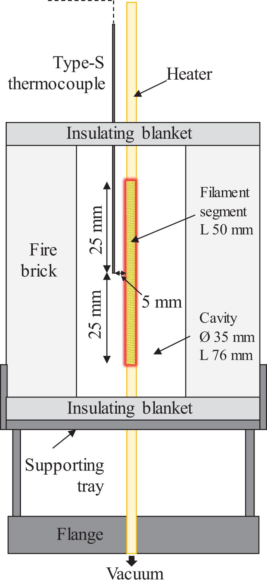
Figure 5. Setup for the volumetric heating capability. The thermocouple tip is positioned in-plane to the central hot zone, 5 mm away from the envelope wall.
Throughout the development of the heaters, maximizing power output per heater while minimizing stress on the filaments, and especially on the envelopes, and therefore minimizing failures, has been an ongoing goal. The filaments described in the previous section are able to achieve a linear power density of ∏∼ 30 W cm–1, but only when operating at an estimated temperature of ∼2,700 K, i.e., much higher than the rated temperature of the alumina envelope. The filaments also required maximization of the coil diameter (to maximize the filament length), which left minimal clearance (<0.3 mm) from the envelope wall. We identified high temperatures and small clearances as a key risk factor for localized heating and consequent envelope failures. To mitigate this failure, we modified the initial design and increased the wire diameter to Ø0.3048 mm, permitting a decrease in coil diameter to ODf ∼ 3.2 mm and an increase in wall clearance (0.7 mm) to evaluate at higher power.
The above changes allowed an increased power output to over 180 W, twice that of the Ø0.254 mm filament. Simply put, the improvement allowed the heater to reach higher power density under milder conditions. Supplementary Figure 4 shows the temperature response in the cavity with a single heater with the increased Ø0.3048 mm filament, reaching a cavity temperature of ∼1,159 K. We further characterized the cyclic temperature response inside the cavity by continuously operating a single heater between 58.5 (1 min) and 190 W (1 min) for over 70 h. Supplementary Figure 5 shows the temperature profile of the middle 10 h (30–40 h). The heating/cooling rate inside the cavity shows a consistent ∼130 K min–1. The maximum (∼1,080 K) and minimum (∼950 K) temperatures per cycle consistently show a negligible variation (±3 K).
The above results motivate the potential of using multiple heaters inside the cavity to boost temperature output at a lower current density per heater. Figures 6A,B show a three-heater setup. The modularity of the heaters enables scale-up by adding units inside the same cavity without significant modification. Figure 6C shows the cavity temperature response with respect to mild current increase of 0.25 A/heater every 5 min. The cavity reaches a temperature of 1,700 K, suitable for the reduction temperature in two-step redox-active metal–oxide thermochemical H2O/CO2 splitting, at a current of 4.25 A/heater and <70% of the heater power (∼375 W total or ∼125 W per heater).
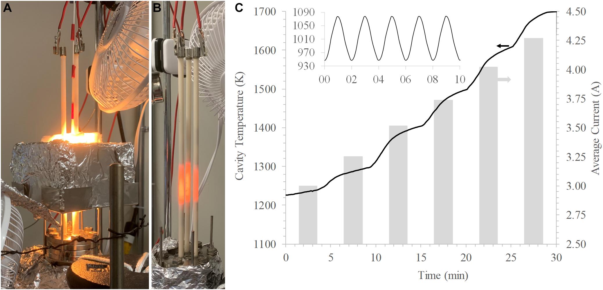
Figure 6. (A) Three heaters (Ø 0.3048 mm) operating inside a firebrick cavity. (B) Direct view of the three heaters. (C) Temperature inside the cavity reaching 1,700 K at a current of 4.25 A/heater with three heaters. (C) Insert: Fast heating cooling (∼130 K min–1) with a single heater in the same setup.
Using multiple heaters also enables greater temperature uniformity in the cavity by creating a partial surround radiation bath. Figure 7 shows the characterization of the temperature distribution inside the three-heater cavity, which confirms this effect. The distribution results from an interpolation of 15 temperature points spanning across the central vertical plane, measured by a bare-tip S-type thermocouple. The thermocouple tip was moved sequentially to each point, and the temperature was recorded upon reaching equilibrium. The experiment was re-evaluated with a B type thermocouple in an alumina protective tube, which showed near-identical results within 1 K. With a steady-state central maximum of 1,777 K, a minimum of ∼1,500 K (15.6% lower) occurs near the lower side on the cavity wall. Restricting convection between the cavity and the ambient environment through the top and bottom openings should further reduce the temperature non-uniformity.
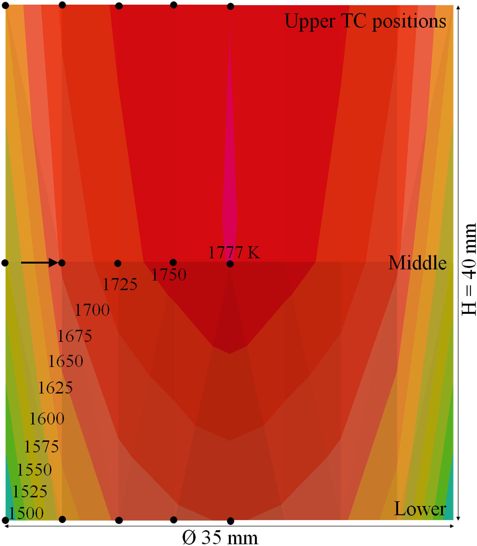
Figure 7. Temperature distribution measured by a single thermocouple inside the firebrick cavity with 3 heaters (Ø 0.381 mm) and total power of 386.8 W. The dots indicate the 15 temperature points where the bare thermocouple tip was positioned. The arrow indicates the orientation of the thermocouple with respect to a particular point.
The three-heater test provides another key result: a surround reactor cavity geometry where the interior is uniformly and radiatively coupled to the heater filaments may leave significant room to decrease the filament temperature by duplication of a few heaters and yet achieve high cavity temperatures, addressing the main heater limitation, namely, the envelope temperature rating. To achieve the best application-specific performance, it is necessary to optimize the filament wire diameters in conjunction with application specifics, such that the filament temperature, under the desired operating conditions, does not exceed the envelope temperature rating (2,150 K in the case of alumina but higher for other suitable ceramics). In this study, the envelope temperature rating was used as the maximum working temperature of the filament. Thus, the optimal wire diameter was determined based on the resistivity as a function of temperature, a fundamental and well-characterized relationship for tungsten.
It is worth noting that even the smaller ODf filaments fill most of the envelope ID. Furthermore, with the thickest wires used in our experiments and considering dense coils, no “gaps” in the filaments exist when observed from the side. These geometrical details make it possible to create a surround geometry using a small number of concentric heater layers, in which all radial lines of sight terminate at a filament. Coupled with the fast filament response time, such geometries offer the possibility of achieving at a low cost cavity temperature changes of several hundred K s–1 for materials (such as redox active metal oxide materials) placed in the cavity.
Due to the characteristics of tungsten filaments, the heaters can provide reliable output even under imperfect power conditions, such as voltage spikes and frequency fluctuations, making them compatible with a wide range of power supply units. Moreover, our experimental experience and the simplicity of the design suggest that the cost to manufacture the heaters can be as little as $0.05/W, at scale.
The radiant heater fulfills the design principle of utilizing low-cost manufacturing techniques and materials while generating substantial heat output in compact and modular units. Consistent performance of generating high-T (>1,800 K) and rapid response (up to 400 K min–1) with respect to modulated power inputs provides a compelling demonstration of the design principle. Simply assembling multiple identical units achieved our objective of volumetric high-density heating, which paves the way for easy scale-up and adaptation into emerging applications, such as thermochemical processes, and offers fast-response high-temperature heating solutions. Due to their inherent robustness, the heaters can use inexpensive power supplies and/or operate in environments with imperfectly conditioned power input. Heaters using renewable electricity will be particularly attractive in sustainable (e.g., thermochemical) production of chemicals and energy carriers, such as syngas, light olefins, ammonia, methanol, and aromatics. The low manufacturing and operating cost of the heaters can enable low-cost production of chemical commodities. In research and practice, these radiant heaters could offer multiple benefits compared to solar simulators, lasers, infrared gold furnaces, or ceramic heaters.
The original contributions presented in the study are included in the article/Supplementary Material, further inquiries can be directed to the corresponding author/s.
XG and IE conducted the core design of the heaters and experiments. ES assisted in the design of the heaters. XG fabricated/characterized the heaters, collected/interpreted data from the experiments, and prepared the manuscript. MB assisted in fabrication/characterization of the heaters and data collection/interpretation. XG, IE, and ES revised the manuscript. IE and ES supervised and funded this work. All authors contributed to the article and approved the submitted version.
This study was based on work supported by the U.S. Department of Energy under Award No. DE–EE0008991.
A U.S. provisional patent application for this invention entitled “High-Temperature Heater Lamp” has been filed on Dec 9, 2019 with a Serial No. 62/945,835.
We wish to acknowledge the team and institutions involved in this work: Arizona State University, Oregon State University, Siemens Corporate Technology, Sandia National Laboratories, and Southwest Research Institute. The assistance in heater fabrication by Brandon Palafox and design by Ryan Milcarek is gratefully acknowledged.
The Supplementary Material for this article can be found online at: https://www.frontiersin.org/articles/10.3389/fenrg.2021.652203/full#supplementary-material
Supplementary Figure 1 | Temperature profiles of a single heater (Ø0.254 mm) at 350–400 K min–1 rapid heating/cooling rate, over 2,000 test cycles (30 s heating and 30 s cooling per cycle). (A) The first 250 cycles of the campaign. (B) The middle 200 cycles of the campaign. (C) The 350 cycles near the end of the campaign.
Supplementary Figure 2 | Filament current response (Ifil) of a single heater (Ø0.3048 mm) inside the cavity when cycling between 15 (1.93 A) and 145.5 W (4.55 A) power outputs every 20 s. Note the two Ifil transient regimes: a fast one (2–3 s) corresponding to filament heating/cooling, and a slower one (∼20 s) corresponding to heating/cooling of the internal lead wires.
Supplementary Figure 3 | (A) A heater (Ø0.254 mm) reaching a steady temperature of 1,835 K at a power input of approximately 90 W. (B) The thermocouple is located next to the ceramic envelope wall, secured by alumina insulation.
Supplementary Figure 4 | Cavity temperature response with a single heater (Ø0.3048 mm) reaching 190 W (5 A) power output.
Supplementary Figure 5 | Cavity temperature response with a single lamp heater (Ø0.3048 mm) when cycling between 58.5 (3.25 A) and 190 W (5 A) power outputs.
Bradley, D., and Entwistle, A. G. (1961). Determination of the emissivity, for total radiation, of small diameter platinum-10% rhodium wires in the temperature range 600-1450∼C. Br. J. Appl. Phys. 12, 708–711. doi: 10.1088/0508-3443/12/12/328
De Vos, J. C. (1954). A new determination of the emissivity of tungsten ribbon. Physica 20, 690–714. doi: 10.1016/S0031-8914(54)80182-0
Hackenberger, W. S., and Speyer, R. F. (1994). A fast-firing shrinkage rate controlled dilatometer using an infrared image furnace. Rev. Sci. Instrum. 65, 701–706. doi: 10.1063/1.1145088
Harris, D. C., Johnson, L. F., Cambrea, L. R., Baldwin, L., Baronowski, M., Zelmon, D. E., et al. (2017). Refractive index of infrared-transparent polycrystalline alumina. Opt. Eng. 56:077103. doi: 10.1117/1.OE.56.7.077103
He, R., Fang, D., Wang, P., Zhang, X., and Zhang, R. (2014). Electrical properties of ZrB2-SiC ceramics with potential for heating element applications. Ceram. Int. 40, 9549–9553. doi: 10.1016/j.ceramint.2014.02.029
He, R., Tong, Z., Zhang, K., and Fang, D. (2018). Mechanical and electrical properties of MoSi2-based ceramics with various ZrB2-20 Vol% SiC as additives for ultra high temperature heating element. Ceram. Int. 44, 1041–1045. doi: 10.1016/j.ceramint.2017.10.043
Hindasageri, V., Vedula, R. P., and Prabhu, S. V. (2013). Thermocouple error correction for measuring the flame temperature with determination of emissivity and heat transfer coefficient. Rev. Sci. Instrum. 84:24902. doi: 10.1063/1.4790471
Jenkins, B., and Mullinger, P. (2008). Industrial and Process Furnaces. Oxford: Butterworth-Heinemann.
Kim, B. N., Hiraga, K., Morita, K., Yoshida, H., Miyazaki, T., and Kagawa, Y. (2009). Microstructure and optical properties of transparent alumina. Acta Mater. 57, 1319–1326. doi: 10.1016/j.actamat.2008.11.010
Kodama, T. (2003). High-temperature solar chemistry for converting solar heat to chemical fuels. Prog. Energy Combust. Sci. 29, 567–597. doi: 10.1016/S0360-1285(03)00059-5
Larrabee, R. D. (1959). Spectral emissivity of tungsten†. J. Opt. Soc. Am. 49, 619–625. doi: 10.1364/JOSA.49.000619
MacIsaac, D., Kanner, G., and Anderson, G. (1999). Basic physics of the incandescent lamp (Lightbulb). Phys. Teach. 37, 520–525. doi: 10.1119/1.880392
Roberts, I. L., Coney, J. E. R., and Gibbs, B. M. (2011). Estimation of radiation losses from sheathed thermocouples. Appl. Therm. Eng. 31, 2262–2270. doi: 10.1016/j.applthermaleng.2011.03.020
Steinfeld, A. (2005). Solar thermochemical production of hydrogen—-a review. Sol. Energy 78, 603–615. doi: 10.1016/j.solener.2003.12.012
Tank, V., and Dietl, H. (1990). Multispectral infrared pyrometer for temperature measurement with automatic correction of the influence of emissivity. Infrared Phys. 30, 331–342. doi: 10.1016/0020-0891(90)90049-2
The Rebound Effect: An Assessment of the Evidence for Economy-Wide Energy Savings from Improved Energy Efficiency | UKERC | The UK Energy Research Centre. (n.d.) Available online at: https://ukerc.ac.uk/publications/the-rebound-effect-an-assessment-of-the-evidence-for-economy-wide-energy-savings-from-improved-energy-efficiency/ (accessed April 9, 2021).
U.S. Department of Energy (n. d.) Hydrogen and Fuel Cell Technologies Office Multi-Year Research, Development, and Demonstration Plan | Department of Energy. Available online at: https://www.energy.gov/eere/fuelcells/downloads/hydrogen-and-fuel-cell-technologies-office-multi-year-research-development (accessed March 3, 2021)
Urbas, J., Parker, W. J., and Luebbers, G. E. (2004). Surface temperature measurements on burning materials using an infrared pyrometer: accounting for emissivity and reflection of external radiation. Fire Mater. 28, 33–53. doi: 10.1002/fam.844
Keywords: high temperature, renewable energy, radiant electric heater, cost-effective, rapid response, thermochemistry
Citation: Gao X, von Boecklin M, Ermanoski I and Stechel EB (2021) Low-Cost Radiant Heater for Rapid Response, High-Temperature Heating. Front. Energy Res. 9:652203. doi: 10.3389/fenrg.2021.652203
Received: 12 January 2021; Accepted: 17 March 2021;
Published: 21 April 2021.
Edited by:
Juan M. Coronado, Institute of Catalysis and Petrochemistry (ICP), SpainReviewed by:
Nathan Siegel, Bucknell University, United StatesCopyright © 2021 Gao, von Boecklin, Ermanoski and Stechel. This is an open-access article distributed under the terms of the Creative Commons Attribution License (CC BY). The use, distribution or reproduction in other forums is permitted, provided the original author(s) and the copyright owner(s) are credited and that the original publication in this journal is cited, in accordance with accepted academic practice. No use, distribution or reproduction is permitted which does not comply with these terms.
*Correspondence: Ivan Ermanoski, aXZhbi5lcm1hbm9za2lAYXN1LmVkdQ==
Disclaimer: All claims expressed in this article are solely those of the authors and do not necessarily represent those of their affiliated organizations, or those of the publisher, the editors and the reviewers. Any product that may be evaluated in this article or claim that may be made by its manufacturer is not guaranteed or endorsed by the publisher.
Research integrity at Frontiers
Learn more about the work of our research integrity team to safeguard the quality of each article we publish.