 Chizu Mao1
 Xianchao Liu
 Tuo Wang
95% of researchers rate our articles as excellent or good
Learn more about the work of our research integrity team to safeguard the quality of each article we publish.
Find out more
BRIEF RESEARCH REPORT article
Front. Energy Res. , 06 April 2021
Sec. Smart Grids
Volume 9 - 2021 | https://doi.org/10.3389/fenrg.2021.644580
This article is part of the Research Topic New Solutions for Smart Grids with High-Penetration Distributed Energy Resources View all 19 articles
Continuous commutation failure is very likely to occur in the hybrid Multi-infeed high-voltage direct current (HMIDC) after AC failure. In order to improve the recovery quality after HMIDC failure, an AC-DC voltage-dependent current order limiter (VDCOL) based on system strength index is proposed in this article. Firstly, the control mode transition process and system recovery process after DC failure are analyzed based on the hybrid multi-infeed DC transmission port model. Then, considering the impact of AC voltage and DC voltage input signals of VDCOL on AC voltage recovery and DC power recovery, respectively, the interaction factor and strength index of the hybrid multi-infeed system are constructed. Moreover, the weight coefficient of AC and DC voltage is calculated according to the strength of the multi-infeed system. Finally, a three-infeed hybrid DC transmission simulation model is built in the MATLAB/Simulink digital simulation platform. The simulation results demonstrate that the rapid recovery strategy proposed in this article can effectively suppress continuous commutation failure and improve the recovery speed of AC voltage and DC power.
High-voltage direct current (HVDC) transmission has gradually become the main method of long-distance, large-capacity, and cross-regional transmission with significant advantages of not being restricted by the system stability and lower cost compared with AC power transmission (Lee et al., 2020; Li et al., 2020). HVDC types include line-commutated converter-based high-voltage direct current (LCC-HVDC) and voltage source converter-based high-voltage direct current (VSC-HVDC) transmission according to commutation methods. The Hybrid multi-infeed direct current (HMIDC) transmission system is formed under multiple VSCs and LCCs with similar electrical distances being connected to the receiving grid. Combining the advantages of LCC and VSC, the HMIDC transmission system has a larger transmission capacity and more flexible operation mode (Li et al., 2018; Bakas et al., 2020). However, when the receiving power grid fails, LCC stations absorb a large amount of reactive power at the same time, and the infeed bus voltage with a short electrical distance will drop quickly. If the AC commutation voltage drops to a certain value, the commutation margin will be insufficient leading to continuous commutation failure (Lin et al., 2020; Song et al., 2020). If the receiving grid can not recover from the commutation failure as soon as possible, it may cause a large area of power supply interruption and greatly affect the power supply reliability of the power grid. Therefore, it is necessary to design a rapid recovery strategy for HMIDC systems.
In order to investigate the recovery behavior of the HMIDC system after failure, the failure recovery process of the first commutation failure by using the steady-state operating curve of the DC system is analyzed in Hong et al. (2020b) and Liu et al. (2020a), where continue decreasing of the extinction angle is validated to be the essential reason for continuous commutation failure. At present, the voltage-dependent current order limiter (VDCOL) is one of the important control units in the HVDC system. Its main function is to limits the reactive power absorbed by the DC system by lowering the DC current order, which is suitable to improve the recovery speed of the feeding system (Nguyen et al., 2017; Huang and Wang, 2018). Zhang et al. (2020) analyzed the control effect of VDCOL under AC voltage and DC voltage drive modes, respectively, and proposed a VDCOL module considering AC voltage input signal conversion, in order to give consideration to the quality of converter bus and DC current recovery. However, the control conversion design of this method is relatively complex, and the improper setting of conversion criteria may be aggravated. Zeng et al. (2017) proposes a coordinated VDCOL control method of multi-infeed DC transmission based on a wide-area measurement system (WAMS). The impact of the fault on each DC transmission electronic system is evaluated based on the measurement results to adjust and control the voltage input signal of the DC subsystem VDCOL. However, this strategy has little consideration of the impact of voltage participating factor on the recovery process of different AC system strengths.
The existing literature mainly focuses on improving the recovery quality of the multi-infeed DC system by improving the input signal of VDCOL. However, the fast recovery control strategy considering the interaction among the infeed systems including VSC stations is urgently needed to be further studied. In order to improve the recovery characteristics of receiving power grids after failure, an AC-DC voltage-dependent current order limiter (VDCOL) based on system strength index in reference (Zeng et al., 2017) is further supplemented for HMIDC. The control mode transition process and recovery process of the HMIDC system after failure are analyzed. Considering the impact of infeed system voltage on AC commutation voltage recovery and DC power recovery, respectively, the relationship between the strength of the infeed system and the AC/DC voltage weight factor is fixed. The VDCOL driven by AC-DC voltage is designed according to the weight factor of infeed system voltage. The effectiveness of the proposed fast recovery strategy is validated by building a triple HMIDC simulation model in MATLAB/Simulink. The results show that the proposed method can avoid the subsequent commutation failure and improve the recovery quality to a certain extent by virtue of the voltage support capacity of the strong power grid and the reactive power regulation capacity of the VSC.
The HMIDC system refers to the network formed when VSC-HVDC and LCC-HVDC are connected with the same or similar electrical distance to the converter bus (Wei et al., 2020). For any hybrid multi-infeed DC transmission system, it is assumed that a total of N inverter stations are connected to the receiving AC grid, which contains k LCC inverter stations and N-k VSC inverter stations. The model of the hybrid multi-infeed DC system can be established based on the multi-port Davenan equivalent method, as shown in Figure 1.
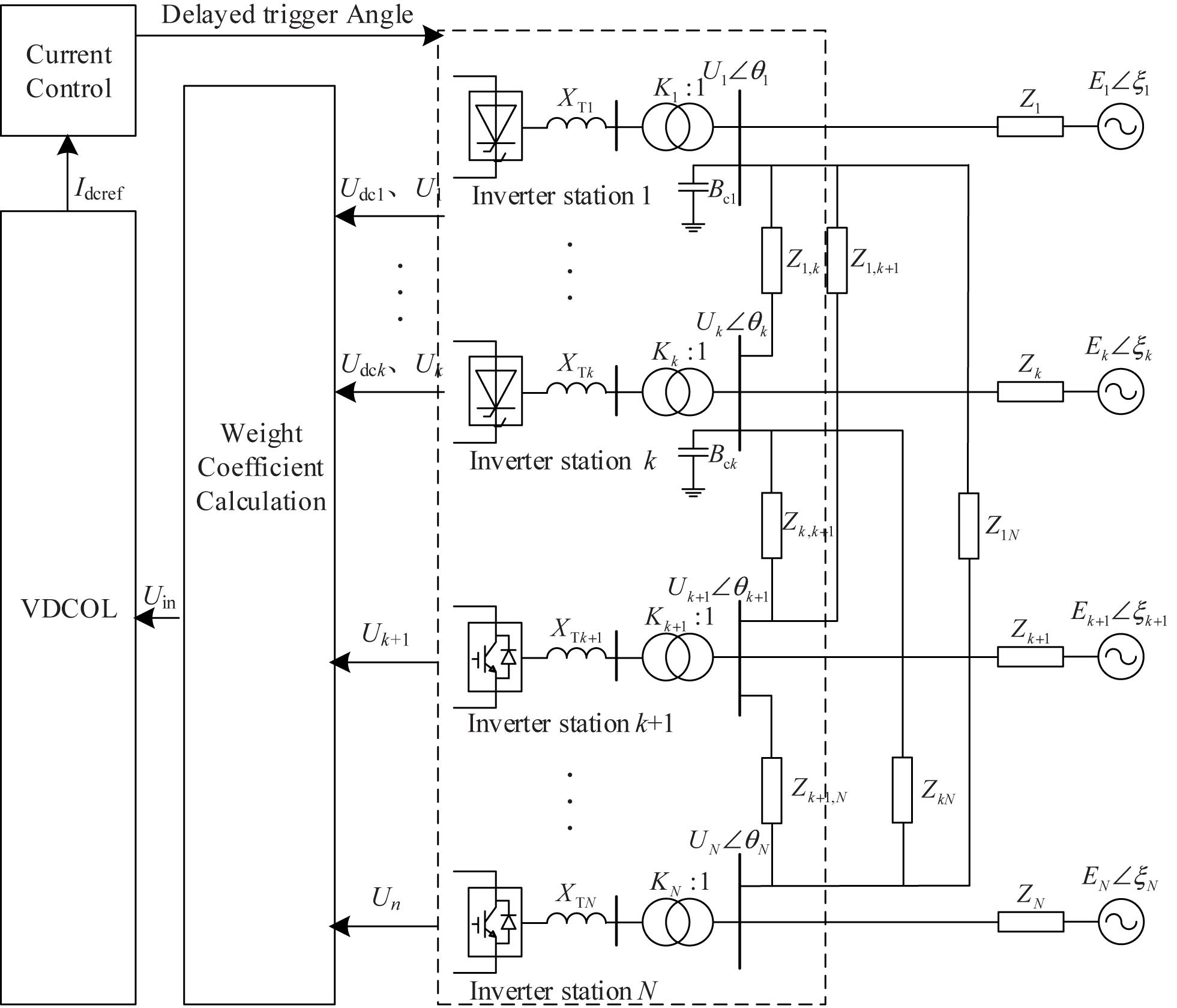
Figure 1. Hybrid multi-infeed DC transmission system model.
VDCOL mitigates the reactive power demand of converter bus by reducing the DC current order, The relationship between voltage and current is as follows (Jiang and Chiang, 2013):
where IH, IL, UH, and UL are the upper and lower limits of DC current and input voltage, respectively. The output current instruction value Id of low-voltage current-limiting control mode depends on the input voltage detection value Uin.
LCC-HVDC inverter adopt DC current control, extinction angle control and current error control (CEC) (Hong et al., 2020a; Xiao and Li, 2020). In normal operation, the LCC inverter is in the state of extinction angle control. When a serious failure occurs, the transient operation process of the HMIDC system is roughly divided into three stages (Liu et al., 2020b), as shown in Figure 2.
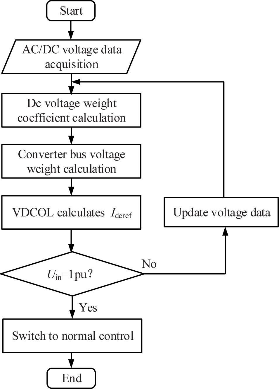
Figure 2. Diagram of VDCOL operation principle.
(1) Start-up stage of CEC. The converter bus voltage of the LCC-HVDC inverter side drops significantly, causing commutation failure. The DC voltage drops and the DC current rises rapidly. The operating point A is shifted to the operating point B. The current deviation control of the LCC inverter is switched to current control, and operating point B moves to point B′.
(2) Start-up stage of VDCOL. VDCOL compulsively reduces the DC current order to control the power transmission, which results in operating point shifts from B to C. The inverter recovers from commutating failure to realize normal commutating. The DC voltage increases, and the operating point moves to point C′. At the same time, the system operates stably under the state of “low voltage and small current” until the fault is removed.
(3) CEC conversion stage. When the system operating point C moves so that the current deviation value is less than the set threshold, the current deviation control converted from the current control to extinction angle control, and finally stabilized at operating point D.
According to the impact of VDCOL on the stability of different infeed systems, VDCOL with mixed input of DC voltage and AC commutation voltage is constructed by collecting voltage data of converter bus. The AC/DC voltage is weighted and used as the input of VDCOL so that DC power recovery not only depends on the DC voltage but also takes into account the voltage recovery of the AC system at the receiving grid. The improved VDCOL control framework is shown in Figure 1.
For the LCC converter, the collected converter bus voltage and DC voltage are weighted by the signal calculation to obtain the nominal value of the input signal of VDCOL. The calculation formula is as follows:
where Uin_i represents the input voltage signal of the VDCOL of the i-th terminal LCC converter; Udci represents the DC voltage of the i-th terminal LCC converter; Uac_j represents the AC voltage of j-th terminal LCC converter; ξi0 represents DC voltage weighting coefficient of the i-th terminal LCC converter; ξij represents AC voltage weighting coefficient of the j-th terminal LCC converter; and k is the number of LCC.
In the recovery process after fault removal, the HMIDC system not only needs rapid recovery of DC power but also needs to consider the degree of disturbance to the voltage stability of the receiving AC grid. The smaller the strength of the receiving grid is, the greater effect of low-voltage current limitation. To this end, the generalized short-circuit ratio (MIESCR) of all hybrid multi-infeed DC systems is established as follows (Liu and Chen, 2013; Xiao et al., 2020):
where SNi is the short-circuit capacity of the i-th terminal receiving grid; QFi is the reactive power compensation capacity of the i-th terminal receiving grid; and PNi is the rated power of the i-th LCC-HVDC.
MIIFji is a generalized multi-feed interaction factor, which is used to evaluate the extent of voltage interaction between DC converter stations (Denis and Göran, 2013; Xiao et al., 2017). It is defined as follows: when a symmetric three-phase reactor is put into the converter bus i, resulting in a 1% decrease in the voltage on the converter bus j, the voltage change rate on the converter bus j.
MIIFji reflects the effect degree of the change of the AC voltage of bus i on bus j.
The larger MIESCR is, the greater receiving AC system strength is, and the change of converter bus voltage or that of the converter bus voltage near DC system has little impact on system stability. Therefore, change of DC voltage can be taken as the main determinant. DC voltage weight coefficient constructed is as follows:
where ξi0 represents DC voltage weighting coefficient of the i-th terminal LCC; CSCRi represents the critical short circuit ratio of the i-th terminal LCC.
Combined with Eqs 3, 4, it can be seen that all AC voltage weight coefficients are expressed as follows:
where ξaci represents the weighting coefficients of the i-th terminal LCC commutation voltage.
As is known from Eqs 5,6, DC voltage weighting coefficient represents the intensity risk degree of the receiving system. The higher the system’s strength security is, the less the impact of the recovery process on the stability of the AC system, and the DC voltage and active power can be the priority recovery targets. On the contrary, the voltage recovery of the AC system should be given priority. The DC voltage weight coefficient of VDCOL is positively correlated with the MIESCR.
In the HMIDC system, DC transmission subsystems with similar electrical distances have strong interaction. In case of failure, the degree of converter bus drop is closely related, which can also affect the fault recovery characteristics of the MIDC system. Therefore, it is necessary to add the participation factor of the commutator bus into the AC input signal to represent the coupling interaction between the multi-infeed DC systems.
The coupling interaction between the DC receiving grids affects the AC voltage recovery speed of the converter bus. If the converter bus i are greatly influenced by bus j, the strength MIESCRj of the j-th terminal receiving system is small, and the weight coefficient of AC commutation voltage Uj of VDCOL at the i-th terminal is larger, which can restore the voltage of the j bus stably and quickly restore DC power of the i-th transmission, improve the frequency stability of the AC system, and reduce power failure loss. Therefore, the voltage weight coefficient of the converter bus should be as follows:
In conclusion, the framework of the HMIDC quick recovery control method can be established in this work. The proposed coordinated control method of VDCOL in the hybrid multi-infeed DC system is summarized as follows:
(1) Collect the converter bus voltage and DC voltage at LCC-HVDC and MMC-HVDC.
(2) Calculate the DC voltage weight coefficient and AC weight coefficient of each infeed system.
(3) Calculate the AC voltage weight coefficient of each infeed system.
(4) VDCOL works and outputs the DC current reference value Idcref.
(5) Input DC current reference value Idcref into current control, and switch to normal control when Uin = 1p.u.
In order to verify the effectiveness of the proposed HMIDC fast recovery control method, the electromagnetic simulation model of the HMIDC system is built in the MATLAB/Simulink, including two LCC-HVDC systems and one MMC-HVDC system. In stable operation, current control (2 kA) is adopted for the LCC-HVDC rectifier station, and extinction angle control (18°) is adopted for the inverter side. The MMC-HVDC rectifier station adopts active power (1000 MW) and reactive power control (0 MVar), while the inverter adopts DC voltage (500 kV) and reactive power control (0 MVar). The main parameters are shown in Table 1.
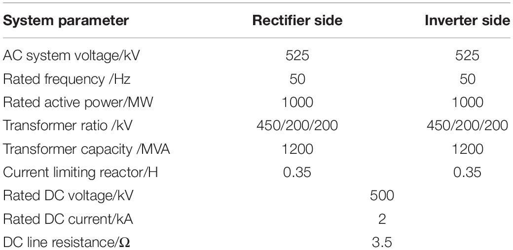
Table 1. Main parameters of HMIDC system.
The two LCC-HVDC and MMC-HVDC are denoted as the first, second and third DC infeed subsystems, respectively, and the equivalent impedance is as follows: Z1 = 5.5 + j20.43Ω, Z2 = 4.7 + j17.6Ω, and Z3 = 5.08 + j18.92Ω; The contact impedance is: Z12 = 3.8 + j47Ω, Z23 = 0.25 + j3.14Ω, and Z31 = 1.3 + j15.7Ω. The effective short-circuit ratio of hybrid multi-feed of the three receiving systems can be calculated based on the above parameters: HMIESCR1 = 2.60, HMIESCR2 = 2.32, and HMIESCR3 = 2.16.
According to the above calculation, the input signals of two VDCOL of LCC-HVDC inverter station can be obtained as follows:
When t = 1.5 s, the three-phase short circuit fault is set at the first LCC-HVDC converter bus, and the fault lasted for 0.1 s. Through comparative analysis, the simulation results of DC voltage VDCOL and the mixed input VDCOL proposed verified the effectiveness of the rapid recovery control. The simulation results are shown in Figure 3.
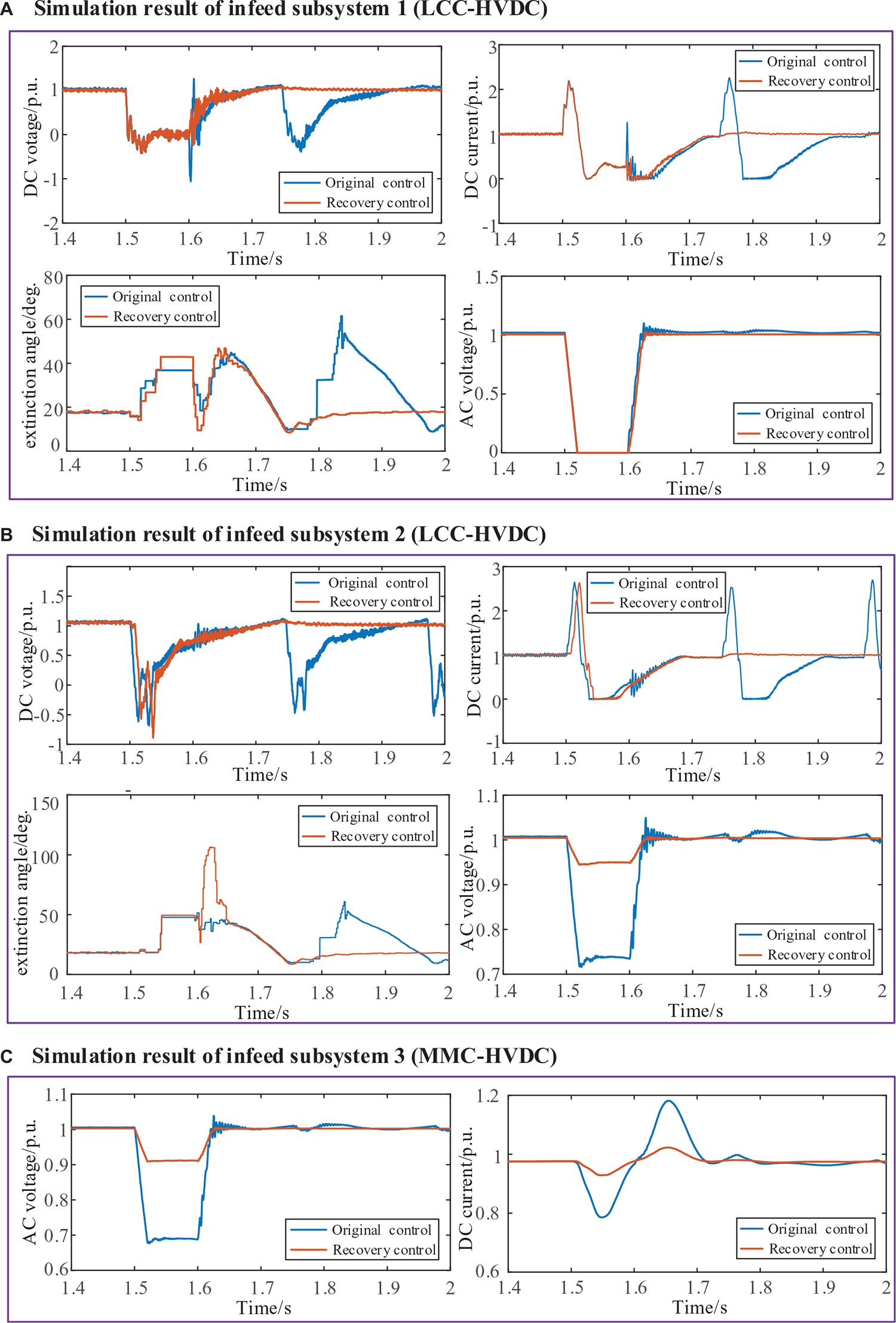
Figure 3. Simulation results of HMIDC after failure. (A) Simulation result of infeed subsystem 1 (LCC-HVDC). (B) Simulation result of infeed subsystem 2 (LCC-HVDC). (C) Simulation result of infeed subsystem 3 (MMC-HVDC).
Figure 3A shows the simulation results of DC voltage, DC current, extinction angle, and inverter converter bus voltage of subsystem 1. The converter bus voltage drops to 0 rapidly when three-phase short-circuit fault occurs (t = 1.5 s), and the DC current rises extremely fast. At this time, the current deviation control is started and converted from extinction angle control to current control. Under the action of two kinds of VDCOL strategy for current limit, DC current declined at about t = 1.53 s, commutation failure has happened once at this point. When the three-phase short circuit fault was cleared at t = 1.6 s, infeed system 1 began to recover. However, due to the rapid rise of the DC current, the active power of the system is restored quickly, and the reactive power demand soars, and the commutation failure of the feed system occurs again at t = 1.75 s for the original control strategy. While the proposed control method includes the local AC voltage into the input signal, which obviously limits the rise rate of the DC current. It can be seen from Figure 3A that the proposed VDCOL has a faster recovery speed and smaller overshoot than the original control system. There were continuous commutation failures (γmin = 7°) at the extinction angle in the scenario with no recovery control, while the addition of recovery control avoided subsequent commutation failures in Figure 3A.
Due to the interaction between subsystem 2 and subsystem 1, when a three-phase short-circuit fault occurs to the converter bus of subsystem 1, the bus voltage will drop to a certain value, the DC voltage will drop, and the DC current will rise at a high speed. At this time, the current deviation control will be started, and the switch from extinction angle control to current control. It can be seen from Figure 2B that the DC current recovery speed of the proposed VDCOL is almost the same as that of the control system without recovery. When t = 1.75 s, the subsequent commutation failure occurred in infeed system 2 under the original control method. On the one hand, the VDCOL makes the DC current recover quickly and increases the demand for reactive power. On the other hand, the SCR of infeed system 2 is small, and the poor AC voltage support capacity of the commutator bus. Under the proposed recovery control method, the voltage recovery of the infeed system 1 with large SCR and VSC suppressed the DC current mutation of the infeed system 2, thus avoiding the subsequent commutation failure.
The simulation results of DC voltage, DC current, and inverter side converter bus voltage of subsystem 3 can be seen in Figure 3C. When the subsystem 1 fault occurs (t = 1.5 s), the voltage on the inverter side of MMC-HVDC decreases, and the transmission power decreases as well, while the rectifier is still in active power control, leading to the rise of DC voltage and the decrease of DC current. The recovery control improves DC current fluctuation degree of MMC-HVDC through the interaction between multi-infeed systems and has a positive effect on the stability of AC and DC systems.
In conclusion, The HMIDC rapid coordinated recovery method based on the improved VDCOL links the multiple DC transmissions together, makes full use of the voltage support capacity of the strong power grid and VSC, and makes the incoming power grid orderly recover the DC current and commutation bus voltage, and reduces the subsequent commutation failure.
In this article, a rapid recovery control strategy based on improved VDCOL is proposed for HMIDC. The simulation results of the three-terminal hybrid multi-infeed DC system show that the improved VDCOL rapid recovery control method can avoid the subsequent commuting failure to a great extent, and at the same time improve the recovery speed and quality of the multi-infeed system compared with the traditional VDCOL. Especially for the short circuit relatively small power grid such as the China Guangdong power grid area, the improved VDCOL rapid recovery coordination control will greatly enhance the disturbance resistance ability of regional weakly infeed power grid and improve the recovery characteristics after failure.
The original contributions presented in the study are included in the article/supplementary material, further inquiries can be directed to the corresponding author.
CM: conceptualization. XL: methodology. QL: software. ZX: validation. YX: formal analysis. TW: data curation. All authors contributed to the article and approved the submitted version.
This research was financially supported by the Science and Technology Project of China Southern Power Grid (CGYKJXM20180388).
CM, QL, and ZX were employed by Maintenance Test Center of EHV Transmission Company.
The remaining authors declare that the research was conducted in the absence of any commercial or financial relationships that could be construed as a potential conflict of interest.
Bakas, P., Okazaki, Y., Shukla, A., Patro, S. K., Ilves, K., Dijkhuizen, F., et al. (2020). Review of hybrid multilevel converter topologies utilizing thyristors for HVDC applications. IEEE Transactions on Power Electronics 36, 174–190. doi: 10.1109/TPEL.2020.2997961
Denis, L. H. A., and Göran, A. (2013). Analysis of voltage and power interactions in multi-infeed HVDC systems. IEEE Transactions on Power Delivery 28, 816–824. doi: 10.1109/TPWRD.2012.2227510
Hong, L., Zhou, X., Liu, Y., Haitao, X., Hanhang, Y., Yandong, C., et al. (2020a). Analysis and improvement of the multiple controller interaction in LCC-HVDC for mitigating repetitive commutation Failure. IEEE Transactions on Power Delivery 2, 1.
Hong, L., Zhou, X., Liu, Y., Xia, H., Yin, H., Chen, Y., et al. (2020b). Analysis and improvement of the multiple controller interaction in LCC-HVDC for mitigating repetitive commutation Failure. IEEE Transactions on Power Delivery 2, 1. doi: 10.1109/TPWRD.2020.3017802
Huang, M., and Wang, J. (2018). Review on optimization control strategy for voltage dependent current order limiter. Guangdong Electric Power 31, 18–27.
Jiang, N., and Chiang, H. D. (2013). Energy function for power system with detailed DC model: construction and analysis. IEEE Transactions on Power Systems 28, 3756–3764. doi: 10.1109/TPWRS.2013.2265402
Lee, G., Kwon, D., and Moon, S. (2020). Method for determining the droop coefficients of hybrid multi-terminal HVDC systems to suppress AC voltage fluctuations. IEEE Transactions on Power Systems 35, 4944–4947. doi: 10.1109/TPWRS.2020.3014805
Li, G., An, T., Liang, J., Jun, L. W., Joseph, T., Jingjing, L., et al. (2020). Power reversal strategies for hybrid LCC/MMC HVDC systems. CSEE Journal of Power and Energy Systems 6, 203–212.
Li, Y., Li, Y., Li, G., Zhao, D., and Chen, C. (2018). Two-stage multi-objective OPF for AC/DC grids with VSC-HVDC: Incorporating decisions analysis into optimization process. Energy 147, 286–296. doi: 10.1016/j.energy.2018.01.036
Lin, S., Liu, J., Liu, L., Thunderstorm, and Fu, C. (2020). A review of commutation failure suppression methods for HVDC systems based on control protection measures. Proceedings of the CSEE. 1–16. [2020-09-12]. http://kns.cnki.net/kcms/detail/11.2107.TM.20200410.1109.026.html
Liu, X., Wang, Z., Zheng, B., et al. (2020a). Mechanism analysis and mitigation measures for continuous commutation failure during the restoration of LCC-HVDC. Proceedings of the CSEE 40, 31631–33171.
Liu, X., Zengping, W., Bowen, Z., et al. (2020b). Mechanism analysis and mitigation measures for continuous commutation failure during the restoration of LCC-HVDC. Proceedings of the CSEE 40, 31631–33171.
Liu, Y., and Chen, Z. (2013). A flexible power control method of VSC-HVDC link for the enhancement of effective short-circuit ratio in a hybrid multi-infeed HVDC System. IEEE Transactions on Power Systems doi: 10.1109/TPWRS.2012.2222057
Nguyen, M. H., Saha, T. K., and Eghbal, M. (2017). Master self-tuning VDCOL function for hybrid multi-terminal HVDC connecting renewable resources to a large power system. IET Generation Transmission & Distribution 11, 3341–3349. doi: 10.1049/iet-gtd.2017.0094
Song, J., Li, Y., Zeng, L., and Zhang, Y. (2020). A review of commutation failure for LCC-HVDC. Automation of Electric Power Systems. 1–12. [2020-09-12]. http://kns.cnki.net/kcms/detail/32.1180.TP.20200718.1726.006.html
Wei, Z., Fang, W., and Jun, L. (2020). Variable extinction angle control strategy based on virtual resistance to mitigate commutation failures in HVDC system. IEEE Access 8, 1–10. doi: 10.1109/ACCESS.2020.2994245
Xiao, H., and Li, Y. (2020). Multi-infeed voltage interaction factor: a unified measure of inter-inverter interactions in hybrid multi-infeed HVDC systems. IEEE Transactions on Power Delivery 35, 2040–2048. doi: 10.1109/TPWRD.2019.2960393
Xiao, H., Li, Y., He, X., et al. (2017). A rapid assessment method of commutation failure immunity level for hybrid multi-infeed HVDC transmission systems. Proceedings of the CSEE 37, 4986–4998. (in Chinese). doi: 10.1049/joe.2017.0424
Xiao, H., Zhang, Y., Duan, X., and Li, Y. (2020). Evaluating Strength of Hybrid Multi-Infeed HVDC Systems for Planning Studies Using Hybrid Multi-Infeed Interactive Effective Short-Circuit Ratio. IEEE Transactions on Power Delivery 2, 1. doi: 10.1109/TPWRD.2020.3020957
Zeng, Q., Li, X., Feng, M., Li, B., and Zeng, X. (2017). Coordinated control method of VDCOLs in MIDC system based on the wide-area measurement system. High Voltage Engineering 043, 1168–1174.
Keywords: HMIDC system, commutation failure, system strength, VDCOL, control method
Citation: Mao C, Liu X, Li Q, Xu Z, Xin Y and Wang T (2021) Rapid Recovery Control Method Based on Improved VDCOLs for Hybrid Multi-Infeed DC Transmission System After AC Failure. Front. Energy Res. 9:644580. doi: 10.3389/fenrg.2021.644580
Received: 21 December 2020; Accepted: 11 March 2021;
Published: 06 April 2021.
Edited by:
Liang Chen, Nanjing University of Information Science and Technology, ChinaReviewed by:
Yanbo Chen, North China Electric Power University, ChinaCopyright © 2021 Mao, Liu, Li, Xu, Xin and Wang. This is an open-access article distributed under the terms of the Creative Commons Attribution License (CC BY). The use, distribution or reproduction in other forums is permitted, provided the original author(s) and the copyright owner(s) are credited and that the original publication in this journal is cited, in accordance with accepted academic practice. No use, distribution or reproduction is permitted which does not comply with these terms.
*Correspondence: Xianchao Liu, bGl1eGlhbmNoYW8yMDE3QGFsaXl1bi5jb20=
Disclaimer: All claims expressed in this article are solely those of the authors and do not necessarily represent those of their affiliated organizations, or those of the publisher, the editors and the reviewers. Any product that may be evaluated in this article or claim that may be made by its manufacturer is not guaranteed or endorsed by the publisher.
Research integrity at Frontiers
Learn more about the work of our research integrity team to safeguard the quality of each article we publish.