 Yaou Shen
 Shinian Peng
 Zhongchun Li
- Science and Technology on Reactor System Design Technology Laboratory, Nuclear Power Institute of China, Chengdu, China
Lead-based liquid metals (LLMs) such as lead–bismuth eutectic (LBE) and lead, are currently the most interesting candidate coolants for fast reactors because of their excellent physical properties, which can improve safety and reduce costs. However, in comparison to other liquid metals, previous research on the flow and heat-transfer characteristics of LLMs has been limited. Therefore, this work carried out flow and heat-transfer experiments in LBE flowing through a circular tube in the Natural Circulation Capability Loop (NCCL) facility. The results show a significantly higher friction factor than that of water flowing in a smooth pipe. Furthermore, the Nusselt numbers were found to be lower than those found in data in the literature for experiments carried out in a smooth tube at low Péclet numbers, while they were higher at high Péclet numbers. Therefore, theoretical analyses were performed for LLMs flowing in both smooth and rough pipes, and the impacts of roughness on the heat transfer of an LLM were examined. The theoretical relations for a smooth pipe and a rough pipe were validated using experimental data from the literature and the results of the NCCL experiments, respectively. The results of the theoretical relation for a smooth pipe fitted the literature data well. The derived theoretical relation for a rough pipe with a relative roughness of 0.004 fitted the NCCL data best. Moreover, it was established from the theoretical analysis that roughness has two competitive impacts on the heat transfer of an LLM: it reduces conductive heat transfer while enhancing convective heat transfer. Because conductive heat transfer is important for liquid metals, even with turbulent flow, a small roughness will lead to heat-transfer deterioration at low Péclet numbers, and it may even deteriorate across the whole typical Péclet-number range. This discovery has important implications for the thermal–hydraulic design of LLM reactors, because corrosion and erosion by an LLM will lead to a rough surface after long operating times.
Highlights
1. Experimental research on the flow and heat-transfer characteristics of LBE was carried out using the NCCL facility.
2. Theoretical analyses of an LLM flowing in both smooth and rough pipes were performed, and relevant relations were established.
3. Impacts of roughness on LLM heat transfer were theoretically analyzed and preliminarily verified using NCCL experimental data.
4. Theoretical analysis showed that a certain small roughness will worsen the heat transfer of an LLM across the whole typical Péclet-number range, which should be considered during thermal–hydraulic design.
Introduction
The idea of using liquid metals as reactor coolants began in the 1950s, and it has received increasing attention in recent years because of the excellent heat transfer characteristics and low moderation ratios of such metals. Among them, lead-based liquid metals (LLMs), such as lead–bismuth eutectic (LBE) and pure lead, have very high boiling temperatures that allow the reactor system to operate at normal pressure, and this eliminates the possibility of coolant boiling. Accidents in pressurized water reactors resulting in deterioration of core heat transfer due to system pressure relief or coolant boiling do not constitute a threat to LLM reactors. Additionally, the chemical inertness of LLMs, in contrast to sodium, eliminates the risk of fire and explosion upon contact with water and air. Therefore, despite problems with corrosion and polonium contamination, LLMs remain one of the most competitive coolant candidates for future reactors.
It is generally believed that the flow characteristics of liquid metals, including LLMs, are similar to those of traditional fluids such as water and air (Isakoff, 1951; Brown et al., 1957; Zheng et al., 2016). However, due to their excellent thermal-conductivity coefficients, the heat-transfer characteristics of these materials under turbulent conditions are significantly different from those of ordinary fluids, and this makes their molecular thermal conductivity important, even under turbulent conditions, and it cannot therefore be neglected (Dwyer, 1976; Reed, 1987).
As a basement geometry, there have been many studies on the heat-transfer characteristics of liquid metals, including LBE, flowing in a circular tube. Various heat-transfer equations have been proposed, and most of these are empirical relations based on fitting of experimental data. Furthermore, all of these empirical relations are built on the structural form of the Lyon–Martinelli semi-empirical relation (Martinelli, 1947; Lyon, 1949). This relation has a structural form comprising the sum of thermal conductive and convective terms, in which the thermal conductive term is a constant and the convective term is related to the Péclet number.
For mercury and alkali metals, a large amount of experimental data is available for developing and validating empirical relations. However, comparatively little experimental data relating to LLMs have been obtained, and few relations exist that have been specifically developed for LLMs (Pacio et al., 2015; Zhang et al., 2020b). Although it has long been believed that the heat-transfer relations of other liquid metals can also be applied to LLM, a recent study (Cheng and Tak, 2006) shows that the turbulent Prandtl numbers of LLMs are significantly higher than those of other liquid metals. Furthermore, LLMs have significant corrosion and erosion effects on stainless-steel structural materials. The surface conditions in actual operation may also be different from those with other metals. However, most studies on the heat-transfer characteristics of LLMs have focused on smooth surfaces.
This study focused on these problems, and heat-transfer experiments with LBE flowing in a circular tube were carried out. Theoretical analysis methods for heat-transfer in LLM tubes were established, theoretically derived relations were obtained, and the influence of roughness on heat transfer in liquid metals was examined. The results have important reference significance for understanding LLM heat-transfer mechanisms and industrial thermal–hydraulic design.
Experimental Methods
Experimental Loop
Thermal–hydraulic experiments with LBE flowing in a circular pipe were conducted using the Natural Circulation Capability Loop (NCCL). The NCCL is a high-temperature experimental facility that has three different running modes: pump driving, gas lift, and pure natural circulation. It was designed for performing experimental measurements of the thermal–hydraulic characteristics of LBE to provide support to the design of lead-cooled fast reactors (LFR) and accelerator-driven systems (DAS). The experimental facility is composed of a primary loop containing LBE and a secondary loop with oil for cooling. The LBE loop is rectangular, and it includes a melting tank, riser, pre-heating system, cooling section, electromagnetic pump (EMP), downcomer, electromagnetic flowmeter (EMF), EMF calibration system, electric heating system, and a measuring instrument. The test section is installed in the bottom of the riser. The secondary loop is designed for the cooling of LBE and is connected with the primary loop through a double-tube heat exchanger. The melting tank is used to store and melt the LBE and is heated by heating wires with a heating power of 6 kW. During the experiments, the upper level of LBE is designed to be located in the center of the LBE–oil heat exchanger, leaving enough space to store argon. The EMF is used to measure the flow rate of liquid LBE and is calibrated by the EMF calibration system with five liquid-level sensors at different heights. The entire LBE loop is wrapped with electric heating wires for pre-heating before the LBE enters. The LBE loop is also wrapped with a layer of insulation to reduce heat loss. All pipes and components of this facility in direct contact with LBE are made from 316 L stainless steel. The general layout of this facility is shown in Figure 1.
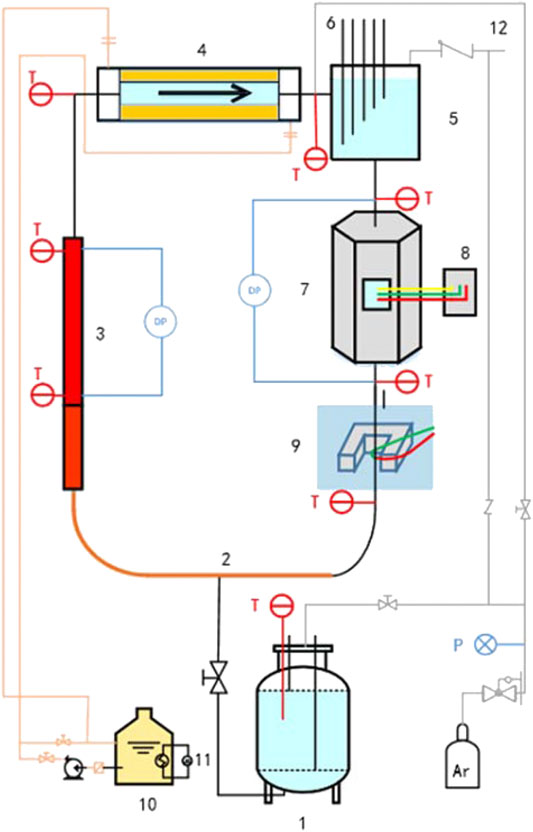
FIGURE 1. Schematic of the NCCL facility, showing: 1. LBE storage and melting tank; 2. pre-heating section; 3. test section; 4. heat exchanger; 5. EMF calibration tube; 6. liquid-level probes; 7. EMP; 8. EMP control system; 9. EMF; 10. oil storage tank; 11. oil heating system; 12. gas outlet.
In these experiments, three circular tubes with different diameters were used as test sections. The internal diameters of the test sections were 20, 35, and 50 mm, and the wall thickness of the test section was 5 mm to ensure a uniform heat flux. The length of the test section was 2 m, and it was divided into two parts, the pre-heating section and the measuring section, each having a length of 1 m. The pre-heating section was designed to ensure that the flow was fully developed before entering the measurement section. The measuring section was equipped with thermocouples and partial-pressure sensors. The heating section was wrapped with 2 mm outer-diameter heating wires with a pitch of 5 mm.
In the experiments, more than 20 thermocouples (TCs), each with an outer diameter of 1.5 mm, were placed at different loop locations to measure the temperature distribution of the LBE. Six thermocouples with an outer diameter of 1.5 mm were used to measure the temperature of the LBE in the measuring section, including two for the inlet and outlet and four for different heights in the measuring section. Four TCs with an outer diameter of 1 mm were embedded in the walls at the same four heights of the test section to measure the wall temperature. A differential pressure sensor was used to measure the pressure drop in the test section. Two pressure sensors were connected to the test section with horizontal tubes to reduce the temperature of the LBE touching the pressure membrane. All the measuring points in the test section are shown in Figure 2. More information about the NCCL experimental facility can be found in a previous report (Zhang et al., 2020a).
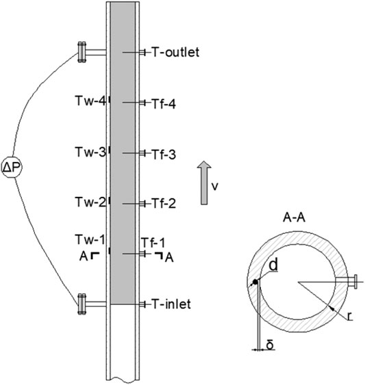
FIGURE 2. Schematic of the test section.
Experimental Conditions and Results
The experiments were conducted under stable temperature and pressure conditions. The variables in this experiment included the inner diameter of the test sections, the mass flow rate of the LBE, the inlet temperature, and the heat flux added to the test section. Previous work (Zhang et al., 2020a) examined seven cases for a 20-mm-diameter pipe and six cases for a 35-mm-diameter pipe. This study completes six cases for a 50-mm-diameter pipe according to the same experimental methods. The experimental conditions for each case are listed in Table 1.
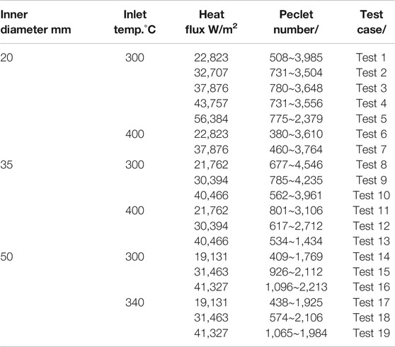
TABLE 1. Experimental conditions for each case.
Figure 3 shows the Nusselt-number results under various Péclet numbers for each case. There is a consistent tendency in the experimental data. Significant differences between the cases are not observed in the results, which means that in the range of the parameters considered in these experiments, the inner diameter, inlet temperature, and heat flux at the wall have little impact on the heat-transfer behavior of LBE.
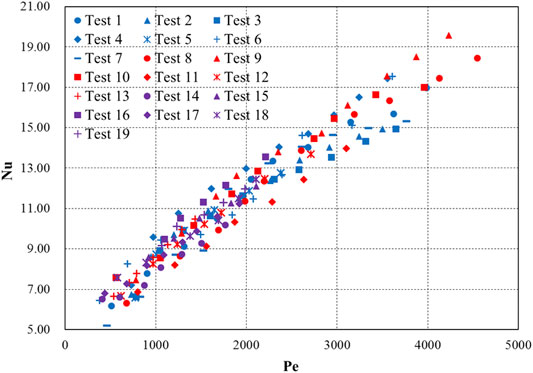
FIGURE 3. Heat-transfer results from the NCCL experiments.
When compared with experimental data in the literature (Johnson et al., 1953; Ibragimov et al., 1960), the Nusselt numbers (Nu) obtained from the NCCL experiments at low Péclet numbers are significantly lower, while the results at high Péclet numbers are higher. The reason for this tendency may be a difference in the wall conditions. The NCCL facility has no oxygen-control system, which may lead to the oxidation of LBE and the corrosion of the inner wall, and thus the condition of a smooth pipe cannot be maintained. Figure 4 shows the friction-factor results of flow experiments carried out in a 20-mm-diameter pipe. The friction factors are higher than the values corresponding to a smooth pipe and are between the ranges of the results for relative roughness h/d from 0.004 to 0.010. The friction-factor results with relative roughnesses of 0.004 and 0.010 were calculated using an empirical relation based on Moody’s curve, which is given later in this report, in Eq. 25.
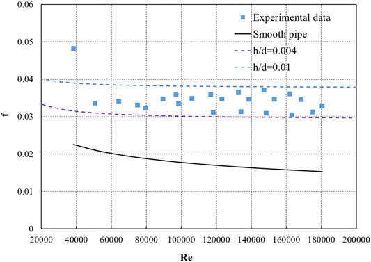
FIGURE 4. Friction-factor (f) results at different Reynolds numbers (Re) from the NCCL experiments.
Analytical Study Methods
Because of a lack of experimental data relating to the flow of LBE or other LLMs, this section describes a theoretical analysis of the impacts of roughness that was carried out based on the methods established for a smooth pipe. These methods are then validated by experimental data from the literature, as detailed in Section 4.1. Section 4.2 then gives the results of these theoretical relations for various relative roughnesses.
Main Assumptions
For liquid metals flowing in a circular tube under fully developed turbulent flow with uniform wall heat flux, Lyon (1949) derived a theoretical heat-transfer integral formula following Martinelli (1947), assumptions:
where: V is the dimensionless velocity, which is defined as
The assumptions used by Lyon (1949) to derive the integral formula are as follows. The system is assumed to operate under steady-state conditions with no end effects, and the physical properties of the liquid metal are constant. The total heat flux in the axial direction, including molecular and eddy heat flux, is assumed to be uniform, while the molecular conductivity perpendicular to the flow direction is assumed not to be affected by eddies, velocity, or axial velocity gradients.
To solve the integral formula, because the turbulent Prandtl number (Prt) of liquid metals was not known, Lyon assumed Prt = 1. Moreover, it was assumed that the flow characteristics of liquid metals were similar to those of ordinary fluids such as water and air. Therefore, experimental data relating to the velocity and eddy diffusivity of momentum distributions of water were used to solve the integral formula. By fitting the numerical integration values of various Péclet numbers (Pe), Lyon’s relation for liquid metals was established as
The constant term of Eq. 2 is called the conductive term, and this represents the contribution of molecular conduction, and the power function of the Péclet number is called the convective term, which expresses the contribution of turbulent convection.
Although the assumption of Prt = 1 and the method of fitting of numerical integration results may result in deviations that have been proven to lead to overestimation of the results of experiments performed later, the form of Eq. 2 is still adopted as the functional form of empirical relations. The deviations can be corrected after fitting using enough experimental data. However, the experimental data available for LLMs are limited. Therefore, a theoretical analysis is needed to discover the heat-transfer characteristics of LLMs.
The theoretical analysis starts from the Lyon–Martinelli integral formula given by Eq. 1. To solve this integral formula, the dimensionless velocity and eddy diffusivity of momentum functions, as well as the turbulent Prandtl number, should first be obtained.
Preparation Before Solving the Integral Equation.
The dimensionless velocity of liquid metals can be obtained by substituting the velocity distribution of the turbulent flow of water in a circular tube, which is determined by Nikuradse (1950) relation, into the definition of dimensionless velocity:
The eddy diffusivity of momentum can be derived by force balance. For a unit-length section of cylindrical fluid, according to force balance:
For a fully developed flow, the axial pressure gradient is constant. Therefore, from Eq. 4, the shear stress is linear with respect to radius, which means that the shear stress at any radius has a relationship with the shear stress at the wall defined by:
However, for a turbulent flow, shear stress is defined as:
Combining Eqs. 5, 6 derives the eddy diffusivity of momentum function as:
According to the research of Cheng and Tak (2006), the turbulent Prandtl numbers for LLMs are greater than those for other liquid metals. Moreover, Cheng and Tak also found that a constant turbulent Prandtl number is more suitable for the form of Lyon’s relation. Therefore, the turbulent Prandtl number used for solving the integral formula of Eq. 1 for an LLM is 2.5, which is the integral mean value of Cheng and Tak’s relations in a typical Péclet-number range.
Solution of the Integral Equation
To solve Eq. 1, the dimensionless velocity and diffusivity of momentum functions given in Eqs. 3, 7 should first be substituted into it:
The following variables are defined to simplify Eq. 8:
Equation 8 can be simplified by substituting Eq. 9 into it and letting
Equation 10 is still a complex integral equation, even after simplification. Therefore, integration by parts is needed. Notice that the denominator has a primitive function as:
The following variables are defined to simplify Eq. 11:
Substituting these variables into Eq. 11 produces:
Expanding Eq. 10 using integration by parts, the following equation can be obtained:
where
Equation 14 consists of many integrand functions in the form of simple multiple functions, and these can thus be integrated independently. The results of Eq. 14 are then:
where
The deviations between Eq. 16 and
The deviations between Eq. 15 and the exact integral value of Eq. 1 are less than 0.4% for a very large region of Péclet numbers between 500 and 10,000. For Péclet numbers less than 500, deviations increase significantly due to the neglect of the non-integrable term. However, the LLM-cooled reactor systems are unlikely to operate at such low Péclet numbers. Therefore, Eq. 15 has sufficient accuracy for practical applications.
Equation 15 can be further simplified by neglecting some terms in the denominator that only impact the results in the low Péclet-number region. This will lead to a further increase in deviations in the low Péclet-number region, but it will have little impact in the high Péclet-number region. The deviation after neglecting some terms is lower than 5.4% for Péclet numbers greater than 1,000, which is still acceptable for the actual application.
Moreover, if we multiply the numerator and the denominator by F and divide by B/C after neglecting some terms in the denominator, Eq. 15 becomes:
According to Eq. 9, coefficient B is a function of the Prandtl and turbulent Prandtl numbers, both of which are constant. The coefficient C is a function of the Péclet number. Therefore, the numerator of Eq. 17 is a sum of a constant term and a function of the Péclet number, which has the same structure as Lyon’s equation.
However, the denominator is a multiple function of
where
For LBE, the typical value of the molecular Prandtl number is 0.0147 (IAEA, 2002; NEA, 2015). The value of the turbulent Prandtl number is the integral mean value of Cheng and Tak’s relation, which is 2.5. Thus, the theoretical heat-transfer equation for LBE flowing through a circular tube with a uniform heat-flux boundary is:
The structure of Eq. 20 is similar to Lyon’s relation and most of the existing relations, but it has a significant difference in that the first (conductive) term, which has a constant value in Lyon’s relation, also has a relationship with the Péclet number. Moreover, the conductive term in Eq. 20 is inversely proportional to the power function of the Péclet number, which means that this value will decrease as the Péclet number increases. The reason for this is that as the Péclet number increases, the turbulent intensity strengthens, and the heat transfer by eddy disturbances increases, which decreases the temperature gradient and thus leads to a decrease in heat transfer by molecular conduction.
Results and Analysis of the Impacts of Roughness
In this section, the theoretical heat-transfer relation of LBE is first compared with experimental data from published literature and the NCCL facility, and then the impacts of roughness are analyzed to explain the differences from the NCCL data.
Validation of the Theoretical Relation
Johnson et al. (1953) produced the first published experimental data on heat transfer in LBE flowing in a tube. Ibragimov et al. (1960) reported experimental data from LBE and Pb seven years after Johnson et al.’s publication, and they proposed an empirical relation based on the structure of Lyon’s relation:
NEA (2015) proposed another relation based on the experimental data of Ibragimov et al. This relation is thus similar, and only the difference is the coefficient of convective term:
Stromquist and Boarts (1953) gave a relation similar to Kirillov and Ushakov’s, with a difference only in the conductive term:
Cheng and Tak (2006) evaluated the existing relations mainly based on Johnson et al.’s data and found that Kirillov and Ushakov’s relation fitted Johnson et al.’s data well in the low Péclet-number region, while Stromquist and Boarts’ relation fitted the data in the high Péclet-number region. Both the relations have the same convective term. Therefore, Cheng and Tak indicated that the conductive term should be a function of the Péclet number for LLM, and they proposed the relation:
The theoretical relation given in Eq. 20 was compared with the literature data as well as the other four relations given in Eqs. 21–24. Figure 5 shows the deviation of Eq. 20 from the experimental data in the literature for LLMs. It can be seen that Eq. 20 fits quite well with Johnson et al.’s data. The maximum deviations from all of the literature experimental data (Johnson et al., 1953; Ibragimov et al., 1960) and Johnson et al. (1953) data are 30 and 10.9%, respectively. Moreover, Eq. 20 shows better conformity with Johnson et al.’s data for high Péclet numbers. The maximum deviation decreases to 5% when the Péclet number is greater than 1,500. The deviation at low Péclet numbers is due to the terms ignored in the derivation of the theoretical relation, as noted above.
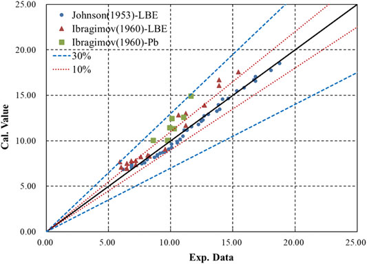
FIGURE 5. Deviation of Eq. 20 from experimental LLM data in the literature.
Figure 6 shows the deviations of Eqs. 21–24 from the experimental data in the literature. Ibragimov et al.’s relation fits his experimental data well, with a maximum deviation of 16.3%, but it underestimates all of Johnson et al.’s data. Stromquist and Boarts’ relation fits Johnson et al.’s data very well for high Péclet numbers, while Kirillov and Ushakov’s relation fits Johnson et al.’s data for lower Péclet numbers better than Stromquist and Boarts’. As a combination of Stromquist and Boarts’ and Kirillov and Ushakov’s relations, Cheng and Tak’s relation fits Johnson et al.’s data quite well for all Péclet numbers, with a maximum deviation of 10.5%.
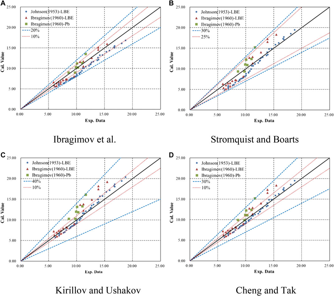
FIGURE 6. Deviations of other relations from experimental LLM data in the literature.
Moreover, it can be seen in Figure 3 that relations that take the conductive term as constant will lead to either an underestimation at low Péclet numbers or an overestimation at high Péclet numbers. If one takes the conductive term as a function decreasing with Péclet number, as with Eq. 20 and Cheng and Tak’s relation, good consistency with experimental data can be obtained across the full range of Péclet numbers.
The relations were then evaluated by the root-mean-square error (RMSE) method using the experimental data form the literature, and the results are shown in Table 2. It can be seen that the theoretical relation given in Eq. 20 has the best consistency with the experimental data.

TABLE 2. RMSE results of relations based on literature data.
Figure 7 shows a comparison of Eq. 20 with the NCCL experimental data and the literature experimental data. In general, the results from Eq. 20 do not fall far from the range of the NCCL data. However, the NCCL data are overestimated at lower Péclet numbers and underestimated at higher Péclet numbers. The literature experimental data have the same trend as the NCCL data; however, for most data points, the deviations are still lower than 15%.
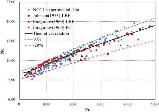
FIGURE 7. Comparison of Eq. 20 with NCCL and literature experimental data.
As noted earlier, a possible reason for the above trend is that the pipe wall is not smooth after testing and operation of the NCCL facility, because it lacks an oxygen-control system. The results of the flow experiments in a 20-mm-diameter pipe after heat-transfer experiments show a significantly higher friction factor at the wall than that for a smooth pipe, as shown in Figure 4. Therefore, the impacts of roughness on the flow and heat-transfer behavior for LLMs in a circular tube were analyzed, and this is elaborated in the next section.
Analysis of the Impacts of Roughness.
For a turbulent flow, the roughness of the walls mainly impacts the friction factor at the wall and the velocity distribution. The friction factor for turbulent flow in a rough pipe can be given by an empirical relation based on Moody (1944) curve:
where
It is easy to find that the velocity distribution function for a rough pipe is a summation of the velocity distribution functions for a smooth pipe and a function N with absolute roughness. The value of N is independent of radius, which means that the gradient of velocity in the radial direction for turbulent flow in a rough pipe is the same as that in a smooth pipe.
As discussed above, to solve the heat-transfer integral equation (Eq. 1), three variables should first be determined: the dimensionless velocity, the eddy diffusivity of momentum, and the turbulent Prandtl number.
Substituting Eq. 26 into Eq. 3, the dimensionless velocity for LLM flow in a rough pipe is:
where the coefficient of friction is related to the friction factor as
For the eddy diffusivity of momentum, because the gradient of velocity is the same as that in a smooth pipe, Eq. 7 is also suitable for LLM flow in a rough pipe; roughness only impacts the friction coefficient. Furthermore, the roughness has no impact on the turbulent Prandtl number, according to Cheng and Tak (2006) turbulent-Prandtl-number model. The model indicates that the average turbulent Prandtl number is only dependent on to the Péclet number. Therefore, by substituting Eqs. 27, 7 into Eq. 1, Eq. 8 becomes:
This only leads to a difference in coefficient A, and the other coefficients are the same as those defined in Eqs. 9, 12, 15:
Therefore, Eq. 17 is still suitable for predicting heat transfer for an LLM flowing in a rough pipe by changing the coefficient A to Eq. 29 and using the friction coefficient given by Eq. 25. The simplified equation used for application then has the same structure as Eq. 20:
The coefficients of Eq. 30 are determined by the relative roughness, which influences the friction coefficient and the velocity-related coefficient A, and the molecular Prandtl number. Table 3 gives the coefficients for different relative roughnesses. Figure 8 shows a comparison of the results of Eqs. 30, 20 for a smooth pipe and the best-fit line of the NCCL experimental data.
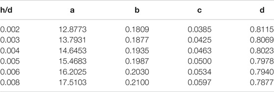
TABLE 3. Coefficients of Eq. 30 for different relative roughnesses.
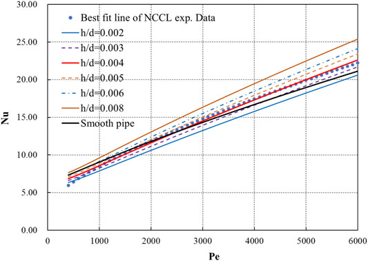
FIGURE 8. Results of Eq. 30 for different relative roughnesses.
The results from Eq. 30 are in general lower than or near the results from Eq. 20 at low Péclet numbers, but they increase faster than the latter as the Péclet number increases. For turbulent flow, roughness has two opposite effects on heat transfer. First, it can enhance the turbulence intensity, which is beneficial to enhancing convective heat transfer. Second, it destroys the bottom layer of laminar flow, thus weakening the influence of conductive heat transfer, as shown in Figure 9. For liquid metals, conduction has a significant effect on heat transfer. Therefore, at low Péclet numbers, due to the low turbulence intensity, the adverse effect caused by the weakening of heat conduction is greater, resulting in the overall deterioration of heat transfer. As the Péclet number increases, turbulence gradually strengthens, and convective heat transfer intensifies, which leads to the improvement of heat transfer.
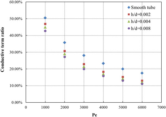
FIGURE 9. Ratios of the conductive term for different relative roughnesses.
Furthermore, lower relative roughnesses have a smaller impact zone, which means that the roughness will mainly impact the bottom layer of laminar flow. Impacts on the turbulence intensity in the area of the turbulent core will only appear when the Reynolds number is large enough. Something else that can be seen in Figure 8 is that the results of Eq. 30 for a relative roughness of 0.004 are very close to the best-fit line of the NCCL experimental data. Figure 10 shows the deviation of Eq. 30 with a relative roughness of 0.004 from the NCCL experimental data.
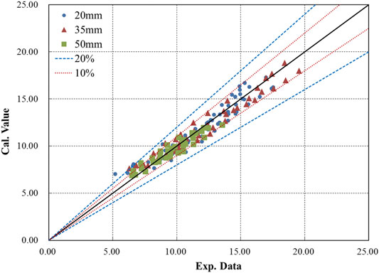
FIGURE 10. Deviation of Eq. 30 with a relative roughness of 0.004 from the NCCL experimental data.
The trends in the predicted results for the NCCL experimental data improve significantly when considering the wall roughness. The results for Péclet numbers lower than 500 are still slightly overestimated due to the neglect of some terms, as with Eq. 20. However, when the Péclet number is greater than 500, the predicted results fit very well with the experimental data, and most results remain within a deviation belt of ±10%. The maximum deviation for Péclet numbers greater than 500 is 21.55%, and this decreases to 14.05% for Péclet numbers greater than 1,000. Figure 11 shows the deviations of the other relations from the NCCL experimental data, although these relations were not developed for LLM flow in a rough pipe.
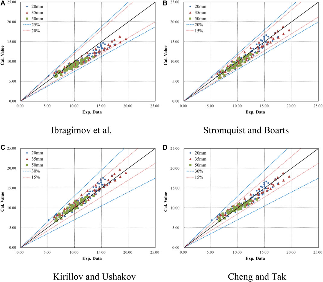
FIGURE 11. Deviations of other relations from the NCCL experimental data.
Ibragimov et al.’s relation underestimates most experimental data, and the deviation increases as the Péclet number increases, while Kirillov and Ushakov’s relation overestimates most data. Stromquist and Boarts’ relation fits the NCCL experimental data very well, because it underestimates the literature data at a low Péclet numbers, which seems proper for a rough pipe. Cheng and Tak’s relation fits the experimental data well at high Péclet numbers but overestimates at low Péclet numbers, as with Kirillov and Ushakov’s relation.
Figure 12 shows the RMSE results for each relation when compared with the NCCL experimental data. Eq. 30 with a relative roughness of 0.004 has the lowest RMSE result of all the relations for heat transfer of an LLM flowing in a pipe. Stromquist and Boarts’ relation also gives good results, but the error increases when the Péclet number is greater than 1,000.
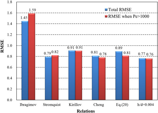
FIGURE 12. RMSE values for the various relations when compared with the NCCL experimental data.
In conclusion, the theoretical relation for heat transfer of an LLM flowing in a rough pipe reveals the impacts of roughness, which can explain the deviation between the NCCL experimental data and experimental data in the literature. The results of Eq. 30 with a relative roughness of 0.004 show good consistency with the NCCL data.
Conclusion
An experimental study of the flow and heat transfer of LBE flowing in a circular tube under uniform heat-flux boundary conditions was carried out at the NCCL facility. A total of 19 cases with different conditions based on three pipes with different inner diameters were tested, and a total of 152 heat-transfer data points, covering a Péclet-number range from 380 to 4,600, were obtained. The heat-transfer results from the NCCL tests showed a different tendency from the experimental data in the literature: at low Péclet numbers the results were smaller, while they were higher at high Péclet numbers. The flow results from the NCCL tests showed a much higher friction factor than expected for a smooth pipe, which reflects the characteristics of a rough pipe. A theoretical study was therefore performed, and the resulting relation was validated using experimental data from the literature. The theoretical relation shows good agreement with the literature data, especially Johnson et al.’s data, and it has the best RMSE result when compared with the other four existing relations that have been developed or considered to be suitable for an LLM. The theoretical relation for an LLM flowing in a rough pipe was then established using the same methods while taking account of the impacts of roughness.
The main conclusions based on these experimental investigations and theoretical analyses are as follows.
1. The heat-transfer results of the NCCL experiments under various conditions indicate that the inner diameter of the pipes, the inlet temperature, the heat flux at the wall, and the physical properties that have strong relations with temperature, have little impact on the Nu–Pe relation of an LLM.
2. The theoretical relation reveals that the heat transfer of an LLM consists of a conductive term and a convective term. The conductive term, which has for a long time generally been considered as a constant, has now been demonstrated to also have a relationship with the Péclet number.
3. Moreover, the value of the conductive term decreases slightly from 4.57 to 3.70 as the Péclet number increases from 1,000 to 6,000, while the ratio of the conductive term to the total heat transfer decreases dramatically from 50.45 to 17.51% due to the rapid increase of the convective term.
4. The roughness has two competing impacts on the heat-transfer behavior of an LLM flowing through a pipe. On the one hand, it reduces conductive heat transfer due to destruction of the laminar sub-layer; on the other hand, it increases convective heat transfer due to the enhancement of turbulent flow. Therefore, heat transfer increases more rapidly as the relative roughness or Péclet number increase. A relative roughness h/d ≥ 0.006 improves the heat transfer, while h/d ≤ 0.002 will cause heat transfer to be worse than that in a smooth pipe in the typical Péclet-number range for an LLM. For relative roughness 0.02 < h/d < 0.006, systems operating at higher Péclet numbers are beneficial for heat transfer.
The theoretical relation for a rough pipe with a relative roughness of 0.004 provides the best fit for the heat-transfer results of the NCCL experiments. However, the relative roughness derived by the relation from the Moody curve, which is used for water, produces friction-factor results from the NCCL experiments that is greater than 0.004. There may be several reasons for this, including the uncertainty of the relevant instruments, differences in the flow characteristics between an LLM and water, and the simplification of the object during theoretical analysis. Therefore, further research on the flow characteristics of LLMs is needed to resolve this question.
Data Availability Statement
The original contributions presented in the study are included in the article/Supplementary Material, further inquiries can be directed to the corresponding author.
Author Contributions
YS: Conceptualization, Methodology, Validation, Formal analysis, Investigation SP: Conceptualization, Resources, Supervision MY: Conceptualization, Methodology, Project administration YZ: Conceptualization, Methodology, Resources JD: Methodology, Resources, Supervision HY: Writing-Reviewing and Editing DH: Writing-Reviewing and Editing ZL: Writing-Reviewing and Editing.
Funding
The authors of this paper appreciate the financial support from: The National Key Research and Development Program of China (No. 2019YFB1901300) National Natural Science Foundation of China (Series number 11705189)
Conflict of Interest
The authors declare that the research was conducted in the absence of any commercial or financial relationships that could be construed as a potential conflict of interest.
Nomenclature
Nu Nusselt number
Pe Péclet number
Pr Prandtl number
Prt turbulent Prandtl number
Re Reynolds number
u velocity
um mean velocity
u* shear velocity
T temperature
P pressure
f friction factor
cf friction coefficient
z axial distance
r radius
rw tube inside radius
y distance from the wall
R radius ratio
Rq variables in successive integrations
V velocity ratio
h absolute roughness
ρ density
υ kinematic viscosity
τ shear stress
τw shear stress at the wall
εM eddy diffusivity of momentum
References
Brown, H. E., Amstead, B. H., and Short, B. E. (1957). Temperature and velocity distribution and transfer of heat in a liquid metal. Trans. Am. Soc. Mech. Eng. 79, 279–285.
Cheng, X., and Tak, N. (2006). Investigation on turbulent heat transfer to lead–bismuth eutectic flows in circular tubes for nuclear applications. Nucl. Eng. Des. 236 (4), 385–393. doi:10.1016/j.nucengdes.2005.09.006
IAEA (2002). Comparative assessment of thermophysical and thermohydraulic characteristics of lead, lead-bismuth and sodium coolants for fast reactors. Vienna, Austria: IAEA-TECDOC-1289.
Ibragimov, M., Subbotin, V. I., and Ushakov, P. A. (1960). Investigation of heat transfer in the turbulent flow of liquid metals in tubes. Atomnaya Energiya 8 (1), 54–56.
Isakoff, S. E. (1951). Heat and momentum transfer in tuebulent flow of mercury, Oak Ridge, TN: United States Atomic Energy Commission Technical Information Service.
Johnson, H. A., Hartnett, J. P., and Clabaugh, W. J. (1953). Heat transfer to molten lead–bismuth eutectic in turbulent pipe flow. J. Heat Transfer 75, 1191–1198.
Kirillov, P., and Ushakov, P. A. (2001). Heat transfer to liquid metals: specific features, methods of investigation, and main relationships. Therm. Eng. 48 (1), 50–59.
Lyon, R. N. (1949). Forced convection heat transfer theory and experiments with liquid metals. Oak Ridge, TN: Oak Ridge National Laboratory.
NEA (2015). Handbook on lead–bismuth eutectic alloy and lead properties, materials compatibility, thermal hydraulics and technologies. Paris, France: OECD.
Nikuradse, J. (1950). Laws of flow in rough pipes. Washington, DC: National Advisory Committee for Aeronautics.
Pacio, J., Morocco, L., and Wetzel, T. (2015). Review of data and correlations for turbulent forced convective heat transfer of liquid metals in pipes. Heat Mass Tran. 51 (2), 153–164. doi:10.1007/s00231-014-1392-3
Reed, C. B. (1987). “Convective heat transfer in liquid metals,” in Chapter 9 from handbook of single-phase convective heat transfer. Editors S. Kakac, R. Shah, and W. Aung (Hoboken, NJ: John Wiley & Sons).
Stromquist, W., and Boarts, R. (1953). Effect of wetting on heat transfer characteristics of liquid metals, Oak Ridge, TN: United States Atomic Energy Commission Technical Information Service.
Zhang, Y., Wang, C., Cai, R., Lan, Z., Shen, Y., Zhang, D., et al. (2020a). Experimental investigation on flow and heat transfer characteristics of lead-bismuth eutectic in circular tubes. Appl. Therm. Eng. 180, 115820. doi:10.1016/j.applthermaleng.2020.115820
Zhang, Y., Wang, C., Lan, Z., Wei, S., Chen, R., Tian, W., et al. (2020b). Review of thermal-hydraulic issues and studies of lead-based fast reactors. Renew. Sustain. Energy Rev. 120, 109625. doi:10.1016/j.rser.2019.109625
Keywords: lead-bismuth eutectic, flow and heat transfer, roughness impacts, turbulent flow, lead-based liquid metal
Citation: Shen Y, Peng S, Yan M, Zhang Y, Deng J, Yu H, Huang D and Li Z (2021) Study of Flow and Heat Transfer Characteristics of Lead-Based Liquid Metals in a Turbulent Tube Flow and the Impacts of Roughness. Front. Energy Res. 9:634964. doi: 10.3389/fenrg.2021.634964
Received: 29 November 2020; Accepted: 12 January 2021;
Published: 25 February 2021.
Edited by:
Jinbiao Xiong, Shanghai Jiao Tong University, ChinaReviewed by:
Chenglong Wang, Xi’an Jiaotong University, ChinaLuteng Zhang, Chongqing University, China
Xi Huang, Shenzhen University, China
Copyright © 2021 Shen, Peng, Yan, Zhang, Deng, Yu, Huang and Li. This is an open-access article distributed under the terms of the Creative Commons Attribution License (CC BY). The use, distribution or reproduction in other forums is permitted, provided the original author(s) and the copyright owner(s) are credited and that the original publication in this journal is cited, in accordance with accepted academic practice. No use, distribution or reproduction is permitted which does not comply with these terms.
*Correspondence: Mingyu Yan, bWVnYXRyb24mI3gwMjAxMDtwcmltZUBob3RtYWlsLmNvbQ==; Jian Deng, ZGVuZ2ppYW5fbnBpY0AxNjMuY29t