- Key Laboratory of Aerospace Thermophysics, Ministry of Industry and Information Technology, School of Energy Science and Engineering, Harbin Institute of Technology, Harbin, China
A compact air-breathing jet hybrid-electric engine coupled with solid oxide fuel cells (SOFC) is proposed to develop the propulsion system with high power-weight ratios and specific thrust. The heat exchanger for preheating air is integrated with nozzles. Therefore, the exhaust in the nozzle expands during the heat exchange with compressed air. The nozzle inlet temperature is obviously improved. SOFCs can directly utilize the fuel of liquid natural gas after being heated. The performance parameters of the engine are acquired according to the built thermodynamic and mass models. The main conclusions are as follows. 1) The specific thrust of the engine is improved by 20.25% compared with that of the traditional jet engine. As pressure ratios rise, the specific thrust increases up to 1.7 kN/(kg·s−1). Meanwhile, the nozzle inlet temperature decreases. However, the temperature increases for the traditional combustion engine. 2) The power-weight ratio of the engine is superior to that of internal combustion engines and inferior to that of turbine engines when the power density of SOFC would be assumed to be that predicted for 2030. 3) The total pressure recovery coefficients of SOFCs, combustors, and preheaters have an obvious influence on the specific thrust of the engine, and the power-weight ratio of the engine is strongly affected by the power density of SOFCs.
Introduction
Combustion engines in aviation sectors are partly responsible for air pollution and carbon dioxide (CO2) warming impacts (Gnadt et al., 2019; Schafer et al., 2019). Widespread electrification of vehicles can contribute to mitigating the damage caused by the power systems (Needell et al., 2016). Fuel cells are advanced and highly efficient energy conversion equipment and can reduce greenhouse gas emissions (Baldi et al., 2019). Newman (Newman, 2015) concluded that proton exchange membrane fuel cells (PEMFC) and solid oxide fuel cells (SOFC) are the only two feasible energy source devices for aerospace applications when the weight and power of fuel cell systems are taken into account. The power density of PEMFCs is improved to a large degree recently, which is beneficial to the propulsion system. However, the production, transportation, and storage of hydrogen are not easy, and noble metal catalyst is needed for the PEMFCs. SOFC can be fueled by traditional hydrocarbon fuel (Chen et al., 2018) and integrated with gas turbines to improve thermal efficiency and power density (Fernandes et al., 2018).
The power density of SOFC gas turbine hybrid systems is small, compared with that of the traditional combustion engines (Collins and McLarty, 2020). Therefore, the system was proposed to apply to unmanned aerial vehicles (UAV), commuter airplanes, and distributed propulsion airplanes. This type of aircraft is sensitive to emission and specific fuel consumption. The advantage of the propulsion system in thermal efficiency can be shown when the weight of the oil load is further higher than that of the power system, which means that the endurance of aircraft is long. (Himansu et al., 2006) first proposed that SOFC gas turbine hybrid systems can serve as core engines of UAVs with high altitude long endurance (HALE) aerospace missions. (Aguiar et al., 2008) showed that the generation efficiency of the hybrid system would be improved by using three fuel cell stacks instead of one stack. Further study found that the preheating requirement for cold atmosphere air and liquid hydrogen is huge when flight altitude is high up to 15–22 km (Tarroja et al., 2009). Commuter airplanes are promising in the civil sector. (Stoia et al., 2016) revealed that the SOFC gas turbine hybrid system is suitable to provide power for all-electric aircraft. It has comparative advantages over internal combustion engines in emission, noise, efficiency etc., even though the power-weight ratio of the hybrid system is low as 300 W/kg. (Stoia et al., 2018) also pointed out that the hybrid system can achieve efficiency in excess of 60% by configuring a hot recycle blower. Moreover, (Woodham et al., 2018) completed the safety analysis for the hybrid power system. (Okai et al., 2012; Okai et al., 2015) built an analytical model of a SOFC gas turbine hybrid power system for a blended wing body distributed propulsion aircraft. The authors showed that weight reduction would be key technology if the engine is expected to come into service. Moreover, the weight problems will be mitigated if the SOFC gas turbine hybrid core is fueled by multi-fuel instead of sole hydrogen fuel (Okai et al., 2017). (Valencia et al., 2015) found that the use of SOFC gas turbine hybrid systems fueled by liquid hydrogen could contribute to reducing by 70% thrust specific fuel consumption on the aircraft with distributed propulsors and boundary layer ingestion, but the weight of the aircraft will increase 40%. (Yanovskiy et al., 2013) showed that the aviation engine with SOFCs is promising by improving fuel cell technologies, even though its weight is high. (Chakravarthula and Roberts, 2017) showed that the SOFC hybrid system for a typical commercial flight outperforms the conventional turbo-generation in both endurance and power-weight ratio at cruising altitude. (Papagianni et al., 2019) showed that the SOFC gas turbine hybrid system could provide 12% in fuel-saving under cruise conditions. (Evrin and Dincer, 2020) evaluated an integrated SOFC system for medium airplanes, which has overall energy and exergy efficiencies of 57.53% and 47.18%, respectively. An engine composing of compressors, SOFCs, and nozzles for high altitude long endurance UAVs was proposed in our previous work (Ji et al., 2019b), which are remarkably different from traditional SOFC gas turbine hybrid systems for aircraft (Ding et al., 2020). The compressor is powered by SOFCs rather than turbines. There are no turbines in the engines. Therefore, the combustion temperature can be further improved. The specific power of the engine is high, but its weight is also huge. Finding a configuration that presents a trade-off between the thrust specific fuel consumption reduction and weight increment is a crucial problem for the engine.
The novelty of this paper is as follows. A compact air-breathing jet hybrid-electric engine coupled with SOFCs fueled by liquefied natural gas is proposed and studied. The main difference between this paper and our previous work (Ji et al., 2020) is system configuration. In this work, an air preheater is integrated with the nozzle. The exhaust in the nozzle expands while exchanges heat with cold compressed air. In addition, a heat-exchanger is integrated with combustors to preheat fuel. In a nutshell, the weight of the engine is decreased, and the nozzle inlet temperature is further increased. The above content is demonstrated in Section System description and cycle analysis. The mass estimation method and thermodynamic models with verification are introduced in Section Mathematics models. Performance analysis is completed in Section Results and discussion.
System Description and Cycle Analysis
The propulsion system configuration is demonstrated in Section System description. There are some differences in the thermodynamic process between the system and the conventional combustion engine, which are analyzed in Section System description.
System Description
The configuration diagram and detailed process flow diagram of the compact air-breathing jet hybrid-electric engine coupled with SOFCs (HEFC engine) fed by liquefied natural gas are shown in Figure 1. Air from the atmosphere at state ① is compressed by an intake and a compressor in turn. Then, the air is divided into two parts. Some are provided for the SOFC cathode, and others are directly utilized by a combustor at state ③. The air exhaust preheater is integrated into the nozzle to heat air from the compressor at state ②. A fuel exhaust heat exchanger is also integrated into the combustor, which is a common method for protecting the combustor wall of ramjets (Jiang et al., 2018). The air and fuel preheated are respectively provided for SOFC cathode and anode. SOFCs generate electricity and drive the compressor by the motor. Next, SOFC exhaust, part compressed air, and some fresh fuel are mixed and burnt in the combustor. Finally, the combustor exhaust expands and outputs propulsion power in the nozzle. The alone heat exchanger and reformer are designed in our previous system (Ji et al., 2019b), which are removed or integrated with other components in this work.
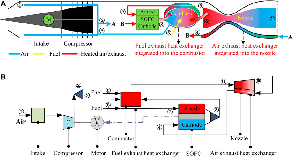
FIGURE 1. The (A) configuration diagram and (B) process flow diagram of a compact air-breathing jet hybrid-electric engine coupled with SOFCs.
The fuel exhaust heat exchanger and the air exhaust preheater are specially designed for the HEFC engine, which is demonstrated as follows. Advantages of the fuel exhaust heat exchanger: 1) the wall of combustors can be cooled by fuels. 2) The liquid fuel is converted into steam, which can be directly utilized by SOFCs. 3) Because the combustor is cooled, the limitation combustion temperature is increased. Advantages of the air exhaust preheater: 1) the wall of nozzles can be cooled by compressed air. 2) The temperature of the air can be improved. There are some differences between the HEFC engine and traditional turbojet engines. For the turbojet engines, turbines are connected to compressors via a shaft (Şöhret, 2018). However, the shaft between turbines and compressors does not exist for the HEFC engine.
Efforts have been made to decrease the weight of HEFC engines, compared with a traditional SOFC gas turbine hybrid system for the electric supply (Lv et al., 2016). The water pump, the evaporator, the mixer, the turbine, the reformer, and the fuel compressor are simplified. The power density of SOFC stacks is 0.17 kW/kg, and that of SOFC systems is 0.035 kW/kg, according to (Chick and Rinker, 2010). Therefore, the improvement of the power density for the HEFC engine is possible. Besides, the power density of SOFCs increases with the increase of years. The power density of SOFCs is about 0.263 kW/kg in 2015, and the one predicted in 2030 is 0.684 kW/kg, according to (Valencia et al., 2015). With the increment of SOFC power density, the power-weight ratio of the HEFC engine may be superior to that of ICEs.
Analysis of Thermodynamic Processes
HEFC engines undergo a special thermodynamic process in the nozzle. The exhaust exchanges heat with cold air while expanding, which is shown in Figure 2A. The working fluids will undergo expansion from state four to state eight if it does not exchange heat with cold air. When the heat exchanging occurs, the working fluids undergo expansion from state four to state five. A simple way can also achieve this in Figure 2B where the combustion outlet temperature and pressure ratios are the same as that in Figure 2A. The working fluids from the compressor at state three are heated to state four. Then, the working fluids undergo heat exchange from state four to state eight and expansion from state eight to state five in turn. However, the nozzle inlet temperature is low by this method. The expansion power in Figure 2B is lower than the one in Figure 2A when the combustor exit temperature and pressure ratio in Figure 2A are the same as that in Figure 2B.
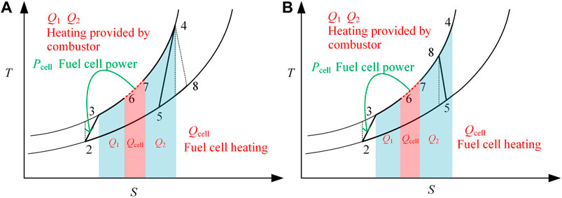
FIGURE 2. Tephigrams of a compact air-breathing jet hybrid-electric engine coupled with SOFCs (A) in this work and (B) in our previous work.
Mathematics Models
The mathematics model of the HEFC engine is built to measure the performance of the propulsion system. First, the thermodynamics and mass models are presented in this section. Then, the performance criterion and solution methods of the system are demonstrated.
Model Assumptions
(1) The HEFC engine is in steady-state operation.
(2) The fuel is liquefied natural gas (100% methane) and is desulfurized.
(3) Gaseous working fluids are considered as ideal gases.
(4) The air contains 21% oxygen and 79% nitrogen.
(5) All components are adiabatic.
(6) Carbon deposition is not considered for the SOFC with internal reforming.
(7) The detailed layout of the fuel exhaust heat exchanger and the air exhaust preheater is not considered.
(8) The mass of the fuel exhaust heat exchanger is neglected.
(9) The mass of fuel pumps and pipelines is assumed as 10% of the total mass of the HEFC engine.
Thermodynamic Models
The thermodynamic model of the HEFC engine is built in this section, which includes the air exhaust preheater model, fuel exhaust exchanger model, intake model, compressor model, and fuel cell model.
Air Exhaust Preheater Model
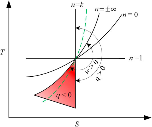
The polytropic process from state four to state five in Figure 2A is re-described in the red zone in Figure 3 with q < 0 and w > 0. n is the polytropic index, and k is the specific heat ratio. w and q are process work and heat.
In this polytropic process, the property of the gas meets the equation.
Therefore,
Subscript 1 represents the inlet of the nozzle, and subscript 2 represents the outlet of the nozzle. The p2 is atmospheric pressure. The process work can be calculated as,
The work can be expressed by Eq. 2.
The equation of state can be expressed as,
The equation of polytropic process work in Eq. 4 can be simplified by Eq. 5 as,
The heat of the polytropic process can be calculated by the first law of thermodynamics.
The ratio of the heat and work in the polytropic process can be expressed as
The Eq. 2 also can be expressed as,
By combining Eq. 9 and Eq. 5, the polytropic index can be expressed as,
The rate of heat exchange is equal to the energy provided for the compressed air. The polytropic index and nozzle outlet temperature can be acquired by combining Eqs 7, 10. The real process in the air exhaust preheater is extremely complicated. However, the polytropic process described by Eqs 1–10 can be achieved by the reasonable arrangement of the preheater and the specific geometrical design of the nozzle, which takes considerable time. In addition, the qualitative conclusion may not be drawn because the analysis of the novel thermal cycle can be limited by complex physical layout models. Therefore, preliminary performance analysis from the perspective of thermodynamics is important. The effects of real physical conditions are considered and can be reflected by total pressure recovery coefficients.
Fuel Exhaust Heat Exchanger Model
The outlet temperature of the fuel exhaust heat exchanger is designed as SOFC anode inlet temperature. The heat transfer rate can be drawn by Eq. 11. The combustion reaction is shown as Eq. 12. Particularly, the oxygen in the combustor can be used up by adding fresh fuel to the combustor. The equivalence ratio of the combustor flow is exactly stoichiometric. The combustion temperature can be calculated according to the energy conservation equation as Eq. 13. The total pressure recovery coefficient of the fuel channel is assumed as 0.92. The total pressure recovery coefficient of combustor
For the air exhaust preheater, the heat transfer rate in the nozzle is equal to the energy provided for the compressed air. The outlet pressure of nozzles is equal to atmospheric pressure. The total pressure recovery coefficient of the air channel
Intake and Compressor Model
The thermal process in an intake is considered as an adiabatic compression process. The total pressure recovery coefficient of the intake is from the practical relation recommended by NASA (Jansen et al., 2017). The outlet parameters of the intake can be drawn by Eqs 18–21. The adiabatic compressor model is assumed in this study (Korakianitis and Wilson, 1992). The outlet parameters of the compressor can be calculated by Eqs 22–25.
Fuel Cell Model
The lumped mathematical model of SOFCs has been demonstrated in our previous paper (Ji et al., 2020). Fuel internal reforming occurs in the SOFC anode channel, which utilizes the water steam from the electrochemical reaction (Ramírez-Minguela et al., 2018) as Supplementary Equations S1, S2 in Supplementary materials Supplementary Table S1, which produces a mass of hydrogen. Hydrogen reacts with oxygen in the three-phase boundary (TPB) as Supplementary Equations S3. The concentrations of hydrogen, water steam, and oxygen in the three-phase boundaries are calculated by porous-media gas-phase transport models (Aguiar et al., 2004) as shown as Supplementary Equations S7–S9 in Supplementary materials Supplementary Table S2. The law of energy conservation is used to calculate the outlet temperature of the SOFC outlet as Supplementary Equation S6. The SOFC outlet temperature is considered as the reforming temperature and electrochemical reaction temperature.
The open-circuit voltage is the maximum voltage that can be achieved by a fuel cell as Supplementary Equation S10 in Supplementary materials Supplementary Table S3. It falls owing to polarization losses (Chan et al., 2001), which include ohmic, concentration, and activation polarization as Supplementary Equation S11. Ohmic losses produce because of resistance to conduction of ions and electrons. This voltage drop can be expressed as Supplementary Equation S12. The electrode overpotential losses can be divided into activation and concentration overpotential, which are connected with the electrochemical reactions. When the electrode reaction is hindered by the effects of mass transport, the concentration overpotentials occur (Aguiar et al., 2004). The concentration polarization can be calculated by Supplementary Equation S13, according to Hughes and Dimitri et al. (Hughes, 2011). The kinetics of reactions on the electrode reaction surface is reflected by activation overpotentials, which is usually represented by the non-linear Butler-Volmer equation (Chan et al., 2001). The anode and cathode activation polarization can be derived as Supplementary Equations S14, S15, respectively. In addition, the anode and cathode exchange densities are affected by microstructure and operational conditions (Yonekura et al., 2011) as Supplementary Equations S16, S17. Fuel cell physical parameters can be easily found in the literature (Chan et al., 2001).
The performance of SOFCs is defined in Supplementary materials Supplementary Table S4. The output power of SOFCs is the production of the voltage, current, and fuel cell area as Supplementary Equation S18. The electric efficiency of fuel cells is the ratio of electric power and fuel energy as Supplementary Equation S19. The fuel utilization of SOFCs is equal to the ratio of molar flow rate of hydrogen consumed and the maximum molar flow rate of hydrogen from fuel as Supplementary Equation S20. The total pressure recovery coefficient of SOFCs
Mass Estimation
For a traditional SOFC gas turbine hybrid system, (Tornabene et al., 2005) have built detailed mass models to estimate its performance. They analyzed the effects of thermal parameters on the component mass. The mass of components is in proportion to the mass flow and is affected by pressure. HEFC engines are similar to the SOFC gas turbine hybrid system. The difference between each other is that the compressor is powered by fuel cells for the former. Therefore, the configuration of feed systems of air and fuels for SOFCs between each other are similar. In this study, the mass equations of compressors, air exhaust preheater, and combustors are fitted by the data provided by (Tornabene et al., 2005) which are shown in Table 1 as Eqs 26–28 and 32–43. The mass of SOFCs is determined by power density as Eqs 30, 31 (Valencia et al., 2015). The specific power of planar SOFCs is predicted to be about 0.263 kW/kg in 2015 and 0.6575 kW/kg in 2030. (Cirigliano et al., 2017) fit the mass equation of motors with R2 of 0.832 as Eq. 29. Apart from the aforementioned components, mixers, splitters, fuel pumps, and pipelines are included in the HEFC engines. The mass sum of these components is assumed as 10% of the total mass of the HEFC engine.
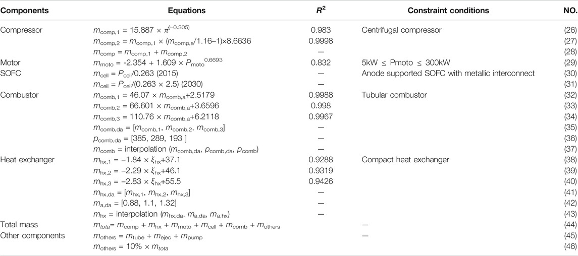
TABLE 1. Mass models of sub-components of the HEFC engines (Tornabene et al., 2005; Valencia et al., 2015; Cirigliano et al., 2017).
Performance Criterion
The performance of the HEFC engine can be evaluated by thrust weight ratio/power-weight ratio, specific impulse, specific thrust, thermal efficiency, overall efficiency, propulsion efficiency.
The mass flow of fuel injected into the engine is.
The energy of fuel is:
The output power of nozzles is w, according to Section Thermodynamic models. Therefore, the outlet velocity of working fluids in the nozzle is:
The effective kinetic energy produced by the working fluids is:
According to momentum theory, the thrust produced by the HEFC engine is
The specific thrust is the ratio of thrust and air flow.
The thrust weight ratio is the ratio of thrust and weight for the HEFC engine. It can be expressed as:
The power-weight ratio is the ratio of kinetic energy and quality. It can be expressed as:
The specific impulse is a measure of how effectively jet engine uses fuel. It is dimensionally equivalent to the generated thrust divided by the propellant mass flow rate.
The thermal efficiency of the HEFC engine is a measure of how efficient the HEFC engine is converting heat to kinetic energy. It can be expressed as:
The propulsion efficiency tells us how efficient the HEFC engine is using the kinetic energy generated by the gas generator for propulsion purposes.
The overall efficiency is the production of thermal efficiency and propulsion efficiency.
Solution Methods
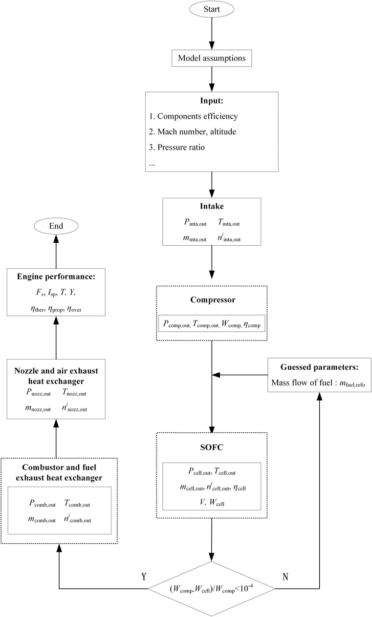
The computer flowchart of the HEFC engine is based on the models described in Section Model assumptions–Performance criterion, which is shown in Figure 4. The first part of this computer code contains the HEFC engine’s input information, including the component efficiency, altitude, Mach number, pressure ratio, etc. In this work, the inlet temperature of the anode and cathode of SOFCs are constants. After intake and compressor calculations, the mass flow of fuel for reformers is guessed. Then, the SOFC calculation begins. The non-linear reforming, electrochemical equations, and cell’s thermal equations are solved simultaneously. The outcomes of SOFC calculation include the SOFC outlet temperature, voltage loss, real voltage, electricity efficiency, etc. If the SOFC power is not equal to the compressor power, the mass flow of fuel for the reformer will be guessed again. In case the convergence conditions of the cycle are fulfilled, the calculation of the combustor, fuel exhaust heat exchanger, nozzle, and air exhaust preheater begins in turn. Finally, the performance parameters of the HEFC engine are output, which includes thrust power ratio, specific impulse, etc.
Model Verification
The purpose of verification is to quantify the error of numerical simulation by the demonstration of convergence for the particular model under consideration (Thacker et al., 2004). SOFCs are a key component in the HEFC engine. The rest of the component models have been widely cited and are without verification assessments. The polarization model of SOFCs has been verified in our previous work (Ji et al., 2019c).
Based on mass models discussed in Section Mass estimation, the calculation results have been validated with that of (Tornabene et al., 2005). The input condition for validating the mass model (Freeh et al., 2005) is shown in Table 2. There is a small difference between our results and Tornabene et al.’s as shown in Table 3. The code-to-code comparisons as a means of calculation verification are completed.

TABLE 2. Input condition for validating the mass model (Freeh et al., 2005).

TABLE 3. Simulation and reference data of the mass model (Tornabene et al., 2005).
Results and Discussion
The performance of the HEFC engine is shown according to the built mathematical model and compared with that of the conventional turbine engine. Then, the effects of pressure ratios on the performance of the engine are demonstrated, and sensitivity analysis is completed.
Performance of the HEFC Engine
Stream data, component mass, performance parameters are shown in Tables 4–6 with zero altitudes and zero velocity. Under the condition, the thrust of the engine is the highest and called installed thrust. The designed compressor pressure ratio is 6. In general, SOFC gas turbine hybrid systems are equipped with a one-stage centripetal compressor. The pressure ratio of the compressor is 2–6 Thacker et al., 2004. The performance of the HEFC engine is shown as Case A in Table 5. The performance of the traditional turbojet engines is shown as Cases B and C. Case B: The fuel equivalence ratio is always equal to the stoichiometric ratio. Case C: The combustion temperature is constant and equal to 2,000K. The models of intakes, compressors, combustors, and turbines (if any) in Case A are completely the same as those in Cases B and C. In addition, fuels for these engines are liquefied natural gas.
The combustion temperature is 2498K in Case A, and the temperature in Case B is 2379K. The equivalence ratios for the two cases are both stoichiometric ratios. Because the pressure ratio is low, the nozzle outlet temperature is considerably high in Table 4, and the thermal efficiency of the HEFC engine is only 0.254 in Table 5. The thermal efficiency in Case A increases by 9.01% and 6.28%, compared with that in Cases B and C. The energy conversion efficiency of fuel cells is high, which converts the chemical energy of fuel into electricity directly. The loss caused by fuel cells becomes heat energy, which can be utilized by the combustor and nozzle. Therefore, the thermal efficiency in Case A is higher than that in Case B and C. The high nozzle inlet temperature will produce huge thrust/power. The specific thrust of the HEFC engine is 1253 N/(kg.s−1). It respectively increases by 4.4% and 20.3%, compared with Cases B and C. The HEFC engine has an obvious advantage over the conventional gas turbine engine in specific power. The specific impulse of the HEFC engine 2,189 s. It is higher than that in Case B and lower than that in Case C. The specific impulse in Case C is highest because the propulsion efficiency in Case C is higher than that in Case A.
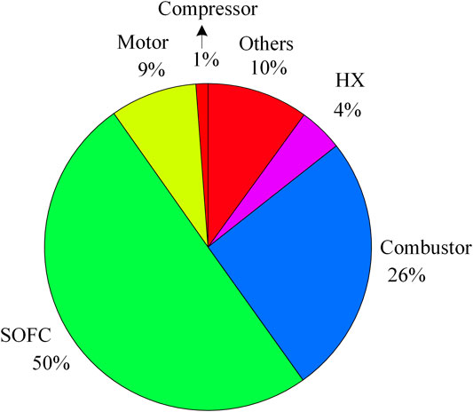
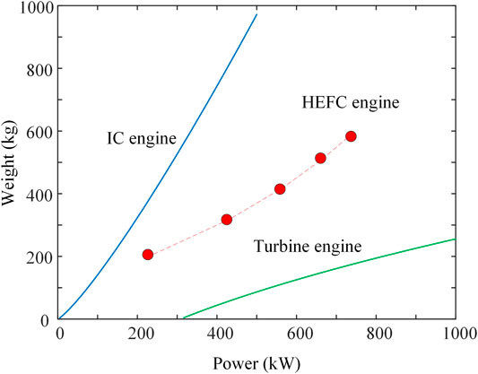
Table 6 shows that the weight of the HEFC engine is high up to 659.1kg, and Figure 5 shows the component mass distribution of the engine. SOFCs makes up most of the weight of the engine, which is over 50%. The sum of combustors weight and motors weight makes up 20%–30% weight of the engine. Decreasing SOFC weight is the key to decrease the weight of the engine. In addition, improving the power-weight ratio of the motors is meaningful work. The diagram of the weight and power of the several power sources is shown in Figure 6. The pressure ratio changes from two to six for the HEFC engine. Data for internal combustion engines and turbine engines are from Ref (Cirigliano et al., 2017). Obviously, the proposed HEFC engine has an advantage over the internal combustion engines and has a disadvantage over the turbine engines. When progress is made in fuel cells for the future, the power-weight ratio of HEFC engines will increase to a large degree. In addition, the specific thrust of the engine under the highest combustion temperature in this work is about 1.7 kN/(kg/s), which is higher than that in our previous paper of about 1.6 kN/(kg/s) under the same operating conditions (Ji et al., 2019a).
Effects of the Pressure Ratio on the HEFC Engine
Pressure ratios are an important parameter for combustion engines. Figure 7 shows the effects of pressure ratios on the HEFC engines and the traditional turbojet engines (Cases A, B, and C). The combustion temperature decreases with increasing pressure ratios for the HEFC engines. However, the temperature increases for the traditional turbojet engines. For these two engines, two stable flow opening systems are built where the inlet and outlet boundaries are the intake inlet and the combustor outlet. Work or heat is added to the systems. For the HEFC engine, the heat energy is added to the opening system. For the turbojet engine, the mechanical work is added to the opening system. As pressure ratios increase, the compressor power increases. The rate of heat transfer by the air exhaust heat exchanger decreases because of the constant inlet temperature of the SOFC cathode. Therefore, the outlet enthalpy or temperature of these opening systems varies. It is bad for the traditional turbojet engine to increase pressure ratios. The highest combustion temperature is close to 2,700K. The turbine will be malfunction. With increasing pressure ratio, the temperature is about 2,300K for the HEFC engine. The combustion temperature in the HEFC engines is the same as the one in the turbojet engine when the pressure ratio is about 11.
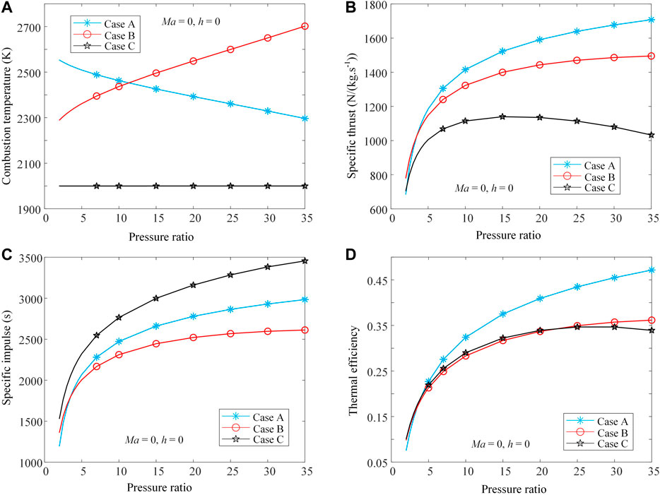
FIGURE 7. Effects of pressure ratios on the (A) thermal efficiency, (B) specific thrust, (C) combustion temperature and (D) specific impulse of the (Case A) HEFC engine and (Case B and Case C) turbojet engines.
Owing to the constant combustion temperature in Case C (2,000K), the specific thrust first increases and then decreases with increasing pressure ratios in Figure 7B. The specific thrust in Case B increases with the increase of the combustion temperature and pressure ratios. In Case A, even though combustion temperature decreases, the specific thrust still increases. The compressor power increases with the increase of pressure ratios and is converted into propulsion power in the nozzle. Thus, the conclusion can be made that the specific power of the HEFC engine increases with pressure ratios. The specific thrust in Case A is superior to that in Case C, which means that the HEFC engine has an advantage over the traditional turbojet engine. In addition, even though the assumption is made that the traditional turbojet engine can be operated at a high temperature up to 2,700K, the HEFC engine still has an obvious advantage over the turbojet engine when the pressure ratio is slightly high. If the pressure ratio is too small, the compressor power is small. The pressure loss in the air exhaust heat exchanger will lead to the performance decline for the HEFC engine. Meanwhile, the conventional turbojet with a few components will have an advantage in the specific thrust.
The specific impulse in Case A and Case B both increases with the increase of specific power under the constant fuel and air flow rate in Figure 7C. In Case C, as the pressure ratio increases, the fuel flow rate decreases. The specific impulse still increases, even though the specific thrust slightly decreases when the pressure ratio is big. It can be seen that the specific impulse in Case C is superior to that in Case A. The reason is that the fuel flow rate in Case C is lower than the one in Case A. The thrust in Case C is also lower than the one in Case A. The specific impulse is the ratio of thrust and fuel flow rate. Therefore, the low flow rate of fuel means that the specific impulse can be high because the variation degree of thrust is lower than the degree of fuel flow rate. The fuel flow rate in Case A is the same as the one in Case B, but the specific impulse in the former is higher than that in the latter. The reason is that thrust in the former is higher than that in the latter. As pressure ratios increases, the advantage increases because the SOFC power increases. In Figure 7D, the thermal efficiency in Case A is higher than that in Cases B or C, which shows that the HEFC engines perform well in the view of thermodynamic cycles. In our previous work (Ji et al., 2019d), the specific impulse of the engine first increases and then decreases where the engine is equipped with the anode and cathode exhaust recirculation. Therefore, the novelty system configuration in this paper can work well under high pressure ratios, which is meaningful.
Sensitivity Analysis
Finding the significant design parameters on the performance of the HEFC engine is important. Therefore, the sensitivity analysis is completed in this section, and the effects of some design parameters on the specific thrust and power-weight ratio of the HEFC engine are investigated and depicted in Figures 8, 9. The variation range for each parameter is about
The total mass flow of fuels is constant with varying fuel utilization because the equivalence ratio is always equal to the stoichiometric ratio. However, this will lead to the change of the fuel flow rate in the SOFC and the one in the combustor. The compressor power and propulsion power are hardly affected. Therefore, the specific thrust is almost not affected by fuel utilization
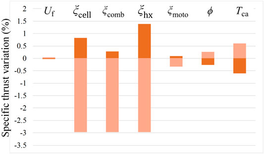
FIGURE 8. Spider diagram of the sensitivity of specific thrust of the HEFC engine vs. seven design parameters.
The weight of the motors or SOFCs is extremely sensitive to the compressor power. Figure 9 shows that the power-weight ratio of the HEFC engine is strongly affected by the transmission efficiency of motors
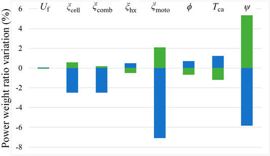
FIGURE 9. Spider diagram of the sensitivity of the power-weight ratio of the HEFC engine vs. eight design parameters.
Conclusion
In summary, a compact air-breathing jet hybrid-electric engine coupled with SOFCs fueled by liquefied natural gas is proposed and studied. Through simulations, the following key conclusions are drawn.
1) The specific thrust of the HEFC engine is increased by 20.3%, compared with that of the traditional turbojet engine with a combustion temperature of 2000K. Meanwhile, thermal efficiency increased by 6.3%. The weight of SOFCs makes up most of the weight of the engine, which is over 50%. The weighted sum of the combustor and motor makes up 20–30% total weight of the engine. In addition, the specific thrust of the engine under the highest combustion temperature in this work is about 1.7 kN/(kg/s), which is higher than that in our previous paper of about 1.6 kN/(kg/s) (Ji et al., 2019a).
2) With increasing pressure ratios, the limitation combustion temperature of the traditional turbojet engine increases, but the temperature of the HEFC engine decreases. Even though the assumption is made that the traditional turbojet engine can be operated at a high temperature up to 2,700K, the HEFC engine still has an obvious advantage over the turbojet engine in specific thrust. In addition, the specific impulse increases with the increase of pressure ratios. However, the specific impulse of the engine in our previous configuration first increase and then decrease (Ji et al., 2019d). The novelty system configuration in this paper can work well under high pressure ratios.
3) According to sensitivity analysis, the total pressure recovery coefficients of SOFCs, combustors, and preheaters have a strong influence on the specific thrust of the HEFC engine. The power-weight ratio of the HEFC engine is strongly affected by the transmission efficiency of motors and the power density of SOFCs.
4) The transmission efficiency and power density of motors will increase if superconducting motors can be applied to the engine. However, the motor needs to be cooled generally, and a suitable cold source is essential. Recently, researchers paid more attention to the light materials for SOFC electrodes and electrolytes. The weight of the SOFC will decrease to a large degree if the new materials can be used.
Data Availability Statement
The raw data supporting the conclusions of this article will be made available by the authors, without undue reservation.
Author Contributions
ZJ: Conceptualization, Methodology, Software, Validation, Writing-original draft. JQ: Supervision, Writing-review & editing. KC: Visualization, Investigation. HL: Data curation. Silong Zhang: Investigation. PD: Writing-review & editing.
Conflict of Interest
The authors declare that the research was conducted in the absence of any commercial or financial relationships that could be construed as a potential conflict of interest.
Supplementary Material
The Supplementary Material for this article can be found online at: https://www.frontiersin.org/articles/10.3389/fenrg.2020.613205/full#supplementary-material.
Abbreviations
HEFC, hybrid-electric engine coupled with SOFCs; ICE, internal combustion engines; SOFC, solid oxide fuel cell.
Nomenclature
cp Specific Heat at Constant Pressure(J/(K·kg))
E Energy (J/mol)
F Faraday constant (96485C/mol) Thrust (N)
F Faraday constant (96485C/mol) Thrust (N)
g Gibbs free energy (J/s)
h Enthalpy (J/s)
j Current density (A/m2)
k Preexponential factor
L Length (m)
m Quality (kg)
M Mass flow (kg/s)
n Molar flow (molar/s)
P Power (J/s)
p Pressure (Pa)
Q Heat energy (J/s)
R universal gas constant
s Entropy (J/s)
T Temperature (K)
u Velocity (m/s)
U Voltage (V)
w Power (J/s)
W Width (m)
Subscripts
act Activation
a, hx Air mass flow for heat exchanger
Ca Cathode
cell Fuel cell
comb combustor
comb,a Exhaust mass flow for combustors
comp Compressor
comp,a Air mass flow for compressors
conc Concentration
ejec Ejector
hx Preheater
hx1 Air exhaust preheater
hx2 Fuel exhaust heat exchanger
in Inlet
inta Intake
ke Kinetic energy
moto Motor
nozz Nozzle
OCP Open circuit voltage
ohmi Ohmic
out Outlet
prop propulsion
pump Pump
refo Reformer
tota Total
TPB Three phase boundary
ther thermal
tube Pipeline.
References
Aguiar, P., Adjiman, C. S., and Brandon, N. P. (2004). Anode-supported intermediate temperature direct internal reforming solid oxide fuel cell. I: model-based steady-state performance. J. Power Sources 138, 120–136. doi:10.1016/j.jpowsour.2004.06.040
Aguiar, P., Brett, D., and Brandon, N. (2008). Solid oxide fuel cell/gas turbine hybrid system analysis for high-altitude long-endurance unmanned aerial vehicles. International Journal of Hydrogen Energy 33, 7214–7223. doi:10.1016/j.ijhydene.2008.09.012
Baldi, F., Wang, L., Pérez-Fortes, M., and Maréchal, F. (2019). A cogeneration system based on solid oxide and proton exchange membrane fuel cells with hybrid storage for off-grid applications. Frontiers in Energy Research 6, 139. doi:10.3389/fenrg.2018.00139
Chakravarthula, V. A., and Roberts, R. A. (2017). “Transient analysis of an innovative cycle integrating a SOFC and a turbogenerator for electric propulsion, Turbo expo: power for land, sea, and air, North Carolina, NC, August 17, 2017 (New York, NY: American Society of Mechanical Engineers), 13.
Chan, S. H., Khor, K. A., and Xia, Z. T. (2001). A complete polarization model of a solid oxide fuel cell and its sensitivity to the change of cell component thickness. J. Power Sources 93, 130–140. doi:10.1016/s0378-7753(00)00556-5
Chen, Y., Deglee, B., Tang, Y., Wang, Z., Zhao, B., Wei, Y., et al. (2018). A robust fuel cell operated on nearly dry methane at 500 °C enabled by synergistic thermal catalysis and electrocatalysis. Nat Energy 3, 1042. doi:10.1038/s41560-018-0262-5
Chick, L., and Rinker, M. (2010). Solid oxide fuel cell (SOFC) technology for greener airplanes. Pacific Northwest National Laboratory: Energy Materials Group.
Cirigliano, D., Frisch, A. M., Liu, F., and Sirignano, W. A. (2017). Diesel, spark-ignition, and turboprop engines for long-duration unmanned air flights. J. Propul. Power 34, 878–892.
Collins, J. M., and McLarty, D. (2020). All-electric commercial aviation with solid oxide fuel cell-gas turbine-battery hybrids. Appl. Energy 265, 114787. doi:10.1016/j.apenergy.2020.114787
Ding, X., Sun, W., Harrison, G. P., Lv, X., and Weng, Y. (2020). Multi-objective optimization for an integrated renewable, power-to-gas and solid oxide fuel cell/gas turbine hybrid system in microgrid. Energy 213, 118804. doi:10.1016/j.energy.2020.118804
Evrin, R. A., and Dincer, I. (2020). Development and evaluation of an integrated solid oxide fuel cell system for medium airplanes. Int. J. Energy Res. 44 (12), 9674–9685. doi:10.1002/er.5525
Fernandes, M. D., Andrade, S. D. P., Bistritzki, V. N., Fonseca, R. M., Zacarias, L. G., Gonçalves, H. N. C., et al. (2018). SOFC-APU systems for aircraft: a review. Int. J. Hydrogen Energy 43 (33), 16311–16333. doi:10.1016/j.ijhydene.2018.07.004
Freeh, J. E., Steffen, C. J., and Larosiliere, L. M. (2005). Off-design performance analysis of a solid-oxide fuel cell/gas turbine hybrid for auxiliary aerospace power. Ohio, OH: National Aeronautics and Space Administration Glenn Research Center. doi:10.1115/fuelcell2005-74099
Gnadt, A. R., Speth, R. L., Sabnis, J. S., and Barrett, S. R. H. (2019). Technical and environmental assessment of all-electric 180-passenger commercial aircraft. Prog. Aero. Sci. 105, 1–30. doi:10.1016/j.paerosci.2018.11.002
Himansu, A., Freeh, J. E., Steffen, C. J., Tornabene, R. T., and Wang, X. Y. J. (2006). “Hybrid solid oxide fuel cell/gas turbine system design for high altitude long endurance aerospace missions,” in ASME 2006 4th International Conference on Fuel Cell Science, Engineering and Technology, Irvine, CA, January 2006, 10.1115/FUELCELL2006-97095
Hughes, D. O. (2011). A hardware-based transient characterization of electrochemical start-up in an SOFC/gas turbine hybrid environment using a 1-D real time SOFC model. North Ave, NH: Georgia Institute of Technology.
Jansen, R., Bowman, C., Jankovsky, A., Dyson, R., and Felder, J. (2017). Overview of NASA electrified aircraft propulsion (EAP) research for large subsonic transports, 53rd AIAA/SAE/ASEE joint propulsion conference, Atlanta, GA, July 10, 2017 (Ohio, OH: National Aeronautics and Space AdministrationGlenn Research Center), 4701.
Ji, Z., Qin, J., Cheng, K., Dang, C., Zhang, S., and Dong, P. (2019a). Thermodynamic performance evaluation of a turbine-less jet engine integrated with solid oxide fuel cells for unmanned aerial vehicles, Appl. Therm. Eng., 160, 114093. doi:10.1016/j.applthermaleng.2019.114093
Ji, Z., Qin, J., Cheng, K., Guo, F., Zhang, S., and Dong, P. (2020). Performance characteristics of a solid oxide fuel cell hybrid jet engine under different operating modes. Aero. Sci. Technol. 105, 106027. doi:10.1016/j.ast.2020.106027
Ji, Z., Qin, J., Cheng, K., Guo, F., Zhang, S., and Dong, P. (2019b). Thermodynamics analysis of a turbojet engine integrated with a fuel cell and steam injection for high-speed flight. Energy 185, 190–201. doi:10.1016/j.energy.2019.07.016
Ji, Z., Qin, J., Cheng, K., Liu, H., Zhang, S., and Dong, P. (2019c). Performance evaluation of a turbojet engine integrated with interstage turbine burner and solid oxide fuel cell. Energy 168, 702–711. doi:10.1016/j.energy.2018.11.088
Ji, Z., Qin, J., Cheng, K., Liu, H., Zhang, S., and Dong, P. (2019d). Thermodynamic analysis of a solid oxide fuel cell jet hybrid engine for long-endurance unmanned air vehicles. Energy Convers. Manag. 183, 50–64. doi:10.1016/j.enconman.2018.12.076
Jiang, Y., Qin, J., Xu, Y., Yu, W., Zhang, S., Chetehouna, K., et al. (2018). The influences of variable sectional area design on improving the hydrocarbon fuel flow distribution in parallel channels under supercritical pressure. Fuel 233, 442–453. doi:10.1016/j.fuel.2018.06.082
Korakianitis, T., and Wilson, D. G. (1992). “Models for predicting the performance of Brayton-cycle engines, Turbo expo: power for land, sea, and air, Cologne, Germany, June 1–4, 1992 (New York, NY: American Society of Mechanical Engineers), 10.
Lv, X., Liu, X., Gu, C., and Weng, Y. (2016). Determination of safe operation zone for an intermediate-temperature solid oxide fuel cell and gas turbine hybrid system. Energy 99, 91–102. doi:10.1016/j.energy.2016.01.047
Needell, Z. A., McNerney, J., Chang, M. T., and Trancik, J. E. (2016). Potential for widespread electrification of personal vehicle travel in the United States. Nature Energy 1 (9), 16112. doi:10.1038/nenergy.2016.112
Newman, T. (2015). Aerospace Systems design Vapor-NASA university design challenge. North Ave, NW: Georgia Institute of Technology.
Okai, K., Fujiwara, H., Nomura, H., Tagashira, T., and Yanagi, R. (2012). “Performance analysis of a fuel cell hybrid aviation propulsion system,” in 10th international energy conversion engineering conference, Atlanta, GA, July, 2012, 4238.
Okai, K., Himeno, T., Watanabe, T., Nomura, H., and Tagashira, T. (2015). “Investigation of FC/GT hybrid core in electrical propulsion for fan aircraft,” in 51st AIAA/SAE/ASEE joint propulsion conference, Orlando, FL, July, 2015, 3888. doi:10.2514/6.2015-3888
Okai, K., Nomura, H., Tagashira, T., and Nishizawa, A. (2017). “Effects of fuel type on aircraft electric propulsion with SOFC/GT hybrid core,” in 53rd AIAA/SAE/ASEE joint propulsion conference, Atlanta, GA, July 7, 2017, 4957.
Papagianni, A., Kavvalos, M., Aslanidou, I., Kyprianidis, K., and Kalfas, A. (2019). “Conceptual design of a hybrid gas turbine-solid oxide fuel cell system for civil aviation,” in International symposium on air breathing engines, ISABE 2019. Canberra, Australia, September 2019, 23–28.
Ramírez-Minguela, J. J., Rangel-Hernández, V. H., Alfaro-Ayala, J. A., Uribe-Ramírez, A. R., Mendoza-Miranda, J. M., Belman-Flores, J. M., et al. (2018). Energy and entropy study of a SOFC using biogas from different sources considering internal reforming of methane. Int. J. Heat Mass Tran. 120, 1044–1054. doi:10.1016/j.ijheatmasstransfer.2017.12.111
Schäfer, A. W., Barrett, S. R. H., Doyme, K., Dray, L. M., Gnadt, A. R., Self, R., et al. (2019). Technological, economic and environmental prospects of all-electric aircraft. Nat Energy 4 (2), 160–166. doi:10.1038/s41560-018-0294-x
Şöhret, Y. (2018). A comprehensive approach to understanding irreversibility in a turbojet. Propulsion and Power Research 7 (2), 129–137. doi:10.1016/j.jppr.2018.05.001
Stoia, T., Atreya, S., and O'Neil, P. (2016). “A highly efficient solid oxide fuel cell power system for an all-electric commuter airplane flight demonstrator,” in 54th AIAA aerospace sciences meeting, San Diego, CA, Jan 2, 2016, 1024.
Stoia, T., Balan, C., Atreya, S., and O'Neil, P. (2018). “Solid oxide fuel cell-steam reformation power system configuration options for an all-electric commuter airplane flight demonstrator,” in 2018 aviation technology, integration, and operations conference, Atlanta, GA, June 25–29, 2018, 4023.
Tarroja, B., Mueller, F., Pratt, J., and Brouwer, J. (2009). “Thermodynamic design analysis of a solid oxide fuel cell gas turbine hybrid system for high-altitude applications,” in 7th international energy conversion engineering conference, Denver, CO, August, 2009, 4526.
Thacker, B. H., Doebling, S. W., Hemez, F. M., Anderson, M. C., Pepin, J. E., and Rodriguez, E. A. (2004). Concepts of model verification and validation. New Mexico, NM: Los Alamos National Lab.
Tornabene, R., Wang, X. Y., Steffen, C. J., and Freeh, J. E., (2005). Development of parametric mass and volume models for an aerospace SOFC/gas turbine hybrid system,” in Turbo expo: power for land, sea, and air, June 6–9, 2005, Nevada, NV, 135–144.
Valencia, E. A., Hidalgo, V., Panagiotis, L., Nalianda, D., Singh, R., and Liu, C. (2015). “Design point Analysis of an hybrid fuel cell gas turbine cycle for advanced distributed propulsion systems,” in 51st AIAA/SAE/ASEE joint propulsion conference, July, 2015, Florida, FL, 3802.
Woodham, K. P., Graydon, P., Borer, N. K., Papathakis, K. V., Stoia, T., and Balan, C. (2018). “FUELEAP model-based system safety analysis,” in 2018 aviation technology, integration, and operations conference, June 24, 2018, 3362.
Yanovskiy, L. S., Baykov, A. V., Raznoschikov, V. V., and Averkov, I. S. (2013). Alternative fuels and perspectives solid oxide fuel cells usage in air transport. ECS Transactions 57 (1), 149. doi:10.1149/05701.0149ecst
Yonekura, T., Tachikawa, Y., Yoshizumi, T., Shiratori, Y., Ito, K., and Sasaki, K. (2011). Exchange current density of solid oxide fuel cell electrodes. ECS Transactions 35 (1), 1007. 10.1149/1.3570081
Keywords: solid oxide fuel cell, jet engine, hybrid electric, liquefied natural gas, thermodynamics
Citation: Ji Z, Qin J, Cheng K, Liu H, Zhang S and Dong P (2021) Design and Performance of a Compact Air-Breathing Jet Hybrid-Electric Engine Coupled With Solid Oxide Fuel Cells. Front. Energy Res. 8:613205. doi: 10.3389/fenrg.2020.613205
Received: 01 October 2020; Accepted: 21 December 2020;
Published: 15 February 2021.
Edited by:
Xiao-Yu Wu, University of Waterloo, CanadaReviewed by:
Valerie Eveloy, Khalifa University, United Arab EmiratesKas Hemmes, Delft University of Technology, Netherlands
Copyright © 2021 Ji, Qin, Cheng, Liu, Zhang and Dong. This is an open-access article distributed under the terms of the Creative Commons Attribution License (CC BY). The use, distribution or reproduction in other forums is permitted, provided the original author(s) and the copyright owner(s) are credited and that the original publication in this journal is cited, in accordance with accepted academic practice. No use, distribution or reproduction is permitted which does not comply with these terms.
*Correspondence: Jiang Qin, cWluamlhbmdAaGl0LmVkdS5jbg==
 Zhixing Ji
 Jiang Qin
 Kunlin Cheng