
94% of researchers rate our articles as excellent or good
Learn more about the work of our research integrity team to safeguard the quality of each article we publish.
Find out more
ORIGINAL RESEARCH article
Front. Energy Res. , 20 January 2021
Sec. Process and Energy Systems Engineering
Volume 8 - 2020 | https://doi.org/10.3389/fenrg.2020.590300
This article is part of the Research Topic Technological and Fundamental Advances in Production, Storage and Utilization of Solar Fuels View all 9 articles
In this present work, simulations of 20 kW furnace were carried out with hydrogen-enriched methane mixtures, to identify optimal geometrical configurations and operating conditions to operate in flameless combustion regime. The objective of this work is to show the advantages of flameless combustion for hydrogen-enriched fuels and the limits of current typical industrial designs for these mixtures. The performances of a semi-industrial combustion chamber equipped with a self-recuperative flameless burner are evaluated with increasing H2 concentrations. For highly H2-enriched mixtures, typical burners employed for methane appear to be inadequate to reach flameless conditions. In particular, for a typical coaxial injector configuration, an equimolar mixture of hydrogen and methane represents the limit for hydrogen enrichment. To achieve flameless conditions, different injector geometries and configuration were tested. Fuel dilution with CO2 and H2O was also investigated. Dilution slows the mixing process, consequently helping the transition to flameless conditions. CO2, and H2O are typical products of hydrogen generation processes, therefore their use in fuel dilution is convenient for industrial applications. Dilution thus allows the use of greater hydrogen percentages in the mixture.
Moving toward carbon-neutral energy generation and consumption becomes more and more urgent, as testified by recent worldwide commitments to fight climate change such as the COP21 (UNFCCC, 2015). On the other hand, global energy consumption is expected to continue increasing and at least 60% of the world’s energy will rely on combustion of bio and fossil derived fuels by 2040 (International Energy Agency, 2017). New breakthroughs in clean production and consumption of fuels are required in order to face the twofold challenge of reducing emissions and increasing demand. Renewable energy sources such as solar energy may represent an attractive solution but since they are intrinsically intermittent, they are not suited for long term energy storage. For this reason the excess energy produced by renewables can be used to synthesize energy carriers which are not fossil-derived such as hydrogen. Hydrogen is a carbon-free fuel and “globally accepted as an environmentally benign secondary form of renewable energy, alternative to fossil fuels” (Nikolaidis and Poullikkas, 2017). The production of hydrogen from renewable sources involves the use of either biomass as a feedstock or water-splitting techniques using solar energy sources, which could become an economically viable solution in the near future (Nikolaidis and Poullikkas, 2017).
Supported by appropriate storage technologies, it is of great interest to understand whether existing systems can be retro-fitted for hydrogen combustion and it is key to develop combustion technologies that allow the consumption of sustainable fuels in a way that satisfies the requirements of thermal efficiency and low pollutant emissions. Several novel technologies have been developed in the last decades to reach this goal and they include Flameless Oxidation (Wünning and Wünning, 1997), Colorless Combustion (Arghode and Gupta, 2010), HiTAC (High Temperature Air Combustion) (Rafidi and Blasiak, 2006) and Moderate or Intense Low-oxygen Dilution (MILD) combustion (Cavaliere and de Joannon, 2004). The common feature of the aforementioned technologies is the diluted fuel charge, result of an intense mixing process, a non-visible flame and uniformly distributed reaction zone. As a result, complete and efficient combustion is usually assured, along with a very low level of noise and fluctuations, absence of soot particles and very low NOx and CO emissions (Wünning and Wünning, 1997), (Szegö et al., 2008). Moreover, the attractiveness of these technologies derives from their fuel flexibility: the process allows the combustion of different fuels over a wide range of calorific values, from biogases (Hosseini and Mazlan, 2013; Choi and Katsuki, 2001; Colorado et al., 2010), pulverized coal (Adamczyk et al., 2017) and liquid biofuels, diesel and kerosene (Xing et al., 2017) to ammonia (Sorrentino et al., 2019), natural gas (Ferrarotti et al., 2018) and methane/hydrogen blends (Parente et al., 2008). For the sake of clarity, in the present work the authors will refer to the above-mentioned technologies as either flameless or MILD combustion interchangeably.
In the two last decades, a number of lab-scale burners have been designed in order to mimic MILD conditions. Among them, the Adelaide Jet-in-Hot-Coflow (AJHC) burner (Dally et al., 2002) and the Delft Jet-in-Hot-Coflow (DJHC) (Oldenhof et al., 2011) have received considerable attention from the combustion community, as their simplified configurations make possible the collection of the high-fidelity experimental data required for turbulent combustion models development and validation. The stand-out feature of flameless combustion is the strong interaction between chemical kinetics timescales and turbulent mixing, so that models based on scale separation between chemistry and turbulence fail in predicting the behavior of such systems (Minamoto et al., 2014). In both AJHC and DJHC MILD conditions are achieved by feeding diluted and hot streams to the coflow, directly affecting the characteristic chemical and mixing timescales of the mixture. With regards to hydrogen-enriched methane mixtures in MILD conditions, several works can be found in literature, for a wide range of reactors and lab-scale burners in various working conditions (Derudi et al., 2007; Sabia et al., 2007; Parente et al., 2008; Galletti et al., 2009; Ayoub et al., 2012). Ayoub et al. (Ayoub et al., 2012) in particular achieved flameless conditions whatever the hydrogen content for a lab-scale pilot furnace with and without air pre-heating. The main difference between the aforementioned studies and the present one relies in the size of the problem: the quasi-industrial furnace presented in this study is designed to mimic operating conditions of “real-life” systems, therefore the features of the flow field may differ significantly from those of lab-scale systems. To the authors’ knowledge no similar studies on comparable systems exist in literature. In industrial systems, the distributed conditions are usually a consequence of internal aerodynamic recirculation and the modification of the local mixing timescales; these strong turbulence-chemistry interactions often prove to be a challenge for the turbulent combustion model to capture. The main issue with these industrial-scale systems however is the relative scarcity of high-fidelity experimental data, which are often limited to few operating conditions. For this reason it is important to bridge the gap between lab-scale burners and industrial systems with quasi-industrial furnaces such as the one employed for this study, as they can preserve the possibility to collect high-fidelity data while working in operating conditions which are closer to “real-life” scenarios.
The complexity of the above-mentioned MILD reaction structures have been the subject of several numerical approaches for both Reynolds Averaged Navier Stokes (RANS) (Galletti et al., 2007) and Large Eddy Simulations (LES) (Duwig et al., 2007). Reaction rate-based models have been proposed in literature and applied to MILD conditions. Among those, the Eddy Dissipation Concept (EDC) (Magnussen, 2005) and the Partially-Stirred Reactor, first proposed by Chomiak (Chomiak, 1990) and employed in the present work, can be highlighted. Both models have been employed in the past by Li et al. (Li et al., 2017; Li et al., 2018) to study the AJHC employing different definitions of the characteristic timescales. In PaSR, as in other reactor-based models, the combustion process is modeled as sequence of mixing and reaction processes in locally uniform zones. Since both the chemical and mixing timescales are explicitly taken into account, their accurate estimation is key in order to properly capture the features of the reacting structures. Among the few studies conducted concerning industrial-like systems, Ferrarotti et al. (Ferrarotti et al., 2018) investigated and provided the validation of the PaSR model of the same combustion chamber studied in this work, fed with natural gas.
The purpose of this paper is to assess the limits of the quasi-industrial furnace equipped with a flameless burner, for hydrogen-methane mixtures. A series of CFD simulations were carried out varying three main parameters: the injector geometry, the stoichiometry of the mixture and fuel dilution, and assessing when flameless conditions were reached. Three different industry-standard injector geometries were chosen. First, an overview of the PaSR model is provided, along with a brief description of the combustion chamber, then a validation of the numerical model with experimental results is presented. Lastly, the results for the various different burner configurations are discussed, in order to asses which is the most influential parameter on the burner behavior and to use the results as feedback to improve the flexibility of the furnace.
RANS numerical simulations were carried out with the commercial code Ansys Fluent 19.3. The mesh was generated with the software Ansys Workbench, taking advantage of the furnace symmetry when possible. The computational domain consists of an angular section of either 45 or 90° depending on the geometrical features considered for the air inlet nozzle: the former for coaxial injectors and 8-holes configurations, the latter for the 4-holes configurations. A grid convergence study was carried out and the resulting grid consists of 216 K cells for the 45° geometry and approximately twice as many for the 90° configuration. Air and fuel inlet mass flows rates were determined according to the operating conditions of each case. The fuel blends were assumed to be fed at 343 K while the air inlet temperature was determined to be 879 K after solving the energy balance across the heat exchanger. For all cases, in order to determine the heat losses associated with the cooling tubes and the furnace walls described in Section 3 the furnace outlet temeperature was set at a value of 1273 K and then the energy balance across the chamber was solved; once the heat losses were determined, a constant heat flux was set as a boundary condition for the cooling tubes and the walls of the chamber. Reynolds stresses were solved using the standard k - ε model. Radiation was taken into account using the Discrete Ordinate (DO) radiation model, using the weighted-sum-of-gray-gases (WSGG) model to account for the radiation properties of the reacting mixture, employing the coefficients proposed by (Smith et al., 1982). The interaction between turbulence and chemistry was modeled using the Partially-Stirred Reactor (PaSR) model. In the PaSR model, as in similar reactor-based models, the computational cell is split into two areas, the reaction structures and the surrounding inert fluid. The reaction progress is then determined by the exchange between the two zones. The mass fraction of the reaction region is estimated considering both the chemical and mixing timescales:
The mean source term for the species transport equation can be therefore expressed as:
where ρ is the mixture density and
A value of
Equation 4 refers to the characteristic timescale of a single species i. The slowest timescale among the active species is selected for the κ parameter 1) in Eq. 2. Li et al. (Li et al., 2018) showed that this approach is a good approximation of the chemical timescales obtained with more sophisticated and demanding techniques such as employing the eigenvalues of the Jacobian matrix of the chemical source terms. A first set of simulations was carried out in order to assess the influence of the kinetic mechanism on the results. The detailed mechanism GRI2.11 (Bowman et al., 2006) (31 species and 175 reactions) and the reduced mechanism KEE (Bilger et al., 1990) (17 species and 58 reactions) were employed.
A brief description of the characteristics of the furnace employed for this study follows. A more detailed report of the features of the burner and the combustion chamber can be found in previous works (Ferrarotti et al., 2018). The quasi-industrial flameless furnace has nominal power of 20 kW. It is fired by a coaxial burner with an integrated finned heat exchanger to recover heat from the exhaust gases and to preheat the combustion air. The fuel inlet nozzle (internal diameter of 8 mm) is located at the center of the bottom wall of the furnace and it is surrounded by a coaxial air jet, for which several possible inlet nozzle configurations are possible. The furnace is equipped with four cooling tubes which allow for different stable operating conditions, in order to simulate the effects of variable loads. The fuel is fed to the burner via a feeding system composed of a set of Mass Flow Controllers for different ranges and fuels and a static mixer to create a homogeneous fuel mixture. Pure H2O and/or CO2 can be also fed to the mixer in order to dilute the fuel blend. A sketch of the furnace can be found in Figure 1.
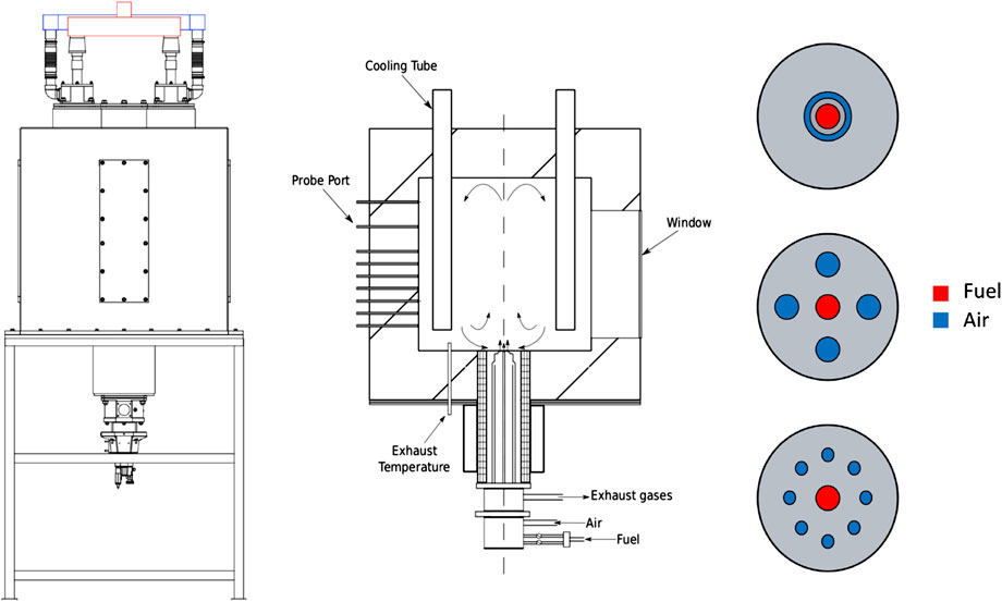
FIGURE 1. Schematic diagram of the quasi-industrial flameless furnace: (left) model, (mid) section and (right) injector configurations (adapted from (Ferrarotti et al., 2020b)).
Before performing the numerical study on hydrogen enrichment, the CFD model was validated to ensure that it provides an accurate representation of the combustion process taking place in the furnace. The CFD model employed in this work was already validated for a number of systems, including the “lab-scale” Adelaide Jet in Hot-Coflow (Li et al., 2018; Ferrarotti et al., 2020a), which is fed with a mixture of methane and hydrogen under different turbulence conditions, and the very same furnace analyzed here, fed with natural gas (Ferrarotti et al., 2018). Two reference cases were chosen to further validate the numerical model for the present study. For both cases a constant input power of 20 kW was fixed and the cooling flow rate was set in order to reach an outlet temperature of 1,000 °C. In both reference cases the geometrical features of the furnace are constant, with a fuel nozzle diameter of 8 mm and a air nozzle diameter of 16 mm. Table 1 summarizes the operating conditions of case 1 and 2.
Figure 2 shows the CFD model results for case 1 and 2 against measured temperature profiles at several axial positions (

FIGURE 2. Validation of the CFD model for cases 1 and 2 against measured temperature profiles at several axial positions: (A)z = 100 mm (B)z = 200 mm (C)z = 300 mm (D)z = 400 mm (E)z = 500 mm (F)z = 600 mm.
A number of different cases have been simulated in order to assess whether flameless conditions are achievable with the current burner configuration in the case of hydrogen methane enrichment. The various operating conditions are summarized in Tables 1–3 sketch of the different geometrical features of the injectors is shown in Figure 1. As mentioned in Section 3, cases 1 and 2 were used to validate the numerical model. A comparison between two kinetic mechanisms, KEE (17 species and 58 reactions) (Bilger et al., 1990) and GRI-2.11 (31 species and 175 reactions) (Bowman et al., 2006) is represented in Figure 3 for case 2. Being the difference between the two lower than 3%, the KEE mechanism was employed for all calculations given the lower computational cost.
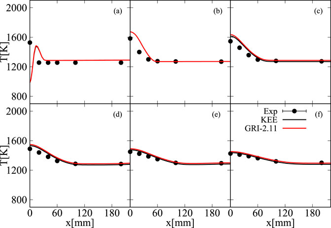
FIGURE 3. Comparison between experimental, GRI2.11 and KEE results for case 2 at several axial locations:
Following the definition given by Cavaliere et al. in (Cavaliere and de Joannon, 2004), MILD conditions are observed when the inlet temperature is higher than the self-ignition temperature of the mixture and the overall increase of temperature due to combustion is lower than the self-ignition temperature:
Starting from case 3, it is possible to notice how typical flameless features are observed with a low hydrogen content in the mixture (5% in vol.). Figure 4 shows temperature and OH contours for case 3; the temperature field is very homogeneous, with a peak temperature of 1411K and the typical delayed ignition observed with pure methane (Ferrarotti et al., 2018). Both conditions defined in Eqs 5, 6 are satisfied for case 3, as the temperature increase is much lower than the self-ignition temperature of the mixture of 884K. Increasing the hydrogen content to
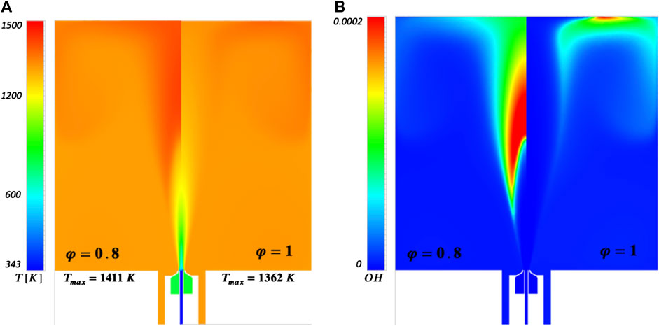
FIGURE 5. Temperature and OH comparison for different equivalence ratio values at 30% H2 (cases 1 and 4).
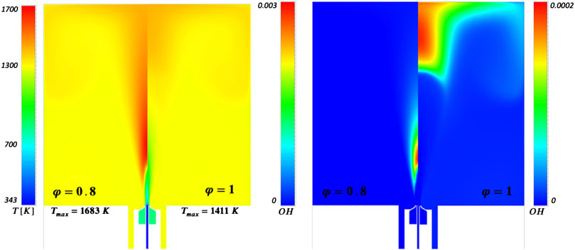
FIGURE 6. Temperature and OH fields comparison for different equivalence ratios with 50% H2 content (cases 5–6).
The shift toward MILD conditions and the consequent peak temperature decrease in the case of
As mentioned earlier, given the geometric configuration of the furnace, the combustion regime is a result of the combination of the turbulent mixing-chemistry interaction and the internal recirculation of the flue gases; the addition of hydrogen to the mixture results in an increased reactivity of the mixture which leads to and increase of the local Damköhler
Multi-hole configuration is a typical industrial configuration for furnace inlets; cases 8 and 9 represent a 4-hole inlet with an air inlet diameter of 9 and 5.4 mm respectively while case 10 represent a 8-hole inlet with an air inlet diameter of 6.4 mm. In cases 9 and 10 the air inlet diameters were chosen in order to respectively decrease and increase the momentum flux ratio between air and fuel with respect to the coaxial configuration. The air inlet diameter in case 10 was chosen so to have the same inlet velocity as in case 8.
Figure 8a shows the temperature and OH contour plots for case 8. With respect to case 7, the peak temperature increases to 2040K and a very well defined conventional flame region forms. Increasing the air inlet velocity has no significant effect as well as one can see from Figure 8b (case 9). In case 10 the number of air inlets is increased to 8: Figure 8c shows how no significant change in the combustion regime happens in these conditions except for an increase in the maximum temperature. In an attempt to increase the mixture residence time, in case 11 the air inlets were tilted by an angle of 15 degrees. As one can see from Figure 9 this change does not lead to a shift in the combustion regime, the only effect being a slight reduction of the peak temperature by about 50K. In order to delay the mixing, the fuel lance length was increased by 100 mm in case 12. With respect to previous cases with the 4-holes inlets, the maximum temperature is reduced by approximately 150K, but a well defined flame region is still present, as it is possible to see from Figure 10. As this effect is not negligible, it was investigated experimentally employing the coaxial 16 mm injector, as it appears to be the best configuration from the CFD results. In order to study the effect of the nozzle length, a different fuel lance of 25 mm is tested. Figure 11 shows the experimental axial and radial temperature profile for a 25%/75% CH_4/H_2 mixture for the base injector and the 25 mm lance as function of the relative distance from the fuel exit (z+); the radial profile is for z= 100 mm. It is possible to observe that the 25 mm fuel lance causes a reduction of the peak temperature by almost 100 K with respect to the base injector, implying that the 25 mm one assures an adequate oxygen dilution. For this reason, the 100 mm lance employed in case 12 was not tested. For this 75% H2 mixture, MILD conditions were achieved.
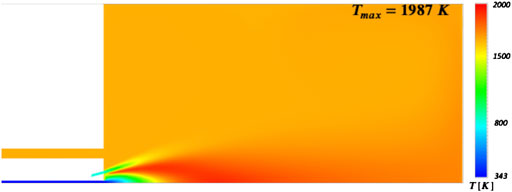
FIGURE 9. Case 11 (70% H2) temperature contour. The tilting of the air inlets does not produce the desired effect.
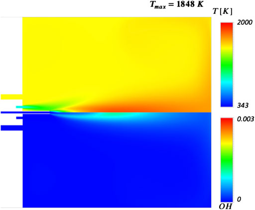
FIGURE 10. Case 12 (70% H2) temperature contour. The increased fuel nozzle length has the effect of reducing the maximum temperature by approximately 150 K.
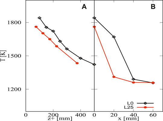
FIGURE 11. Averaged axial and radial (z = 100 mm) temperature profiles for 75% H2. Axial profile shown as function of z+. Averaged experimental uncertainty of 10K.
Having analyzed cases 7–12, it appears that MILD conditions with high levels of hydrogen enrichment (above 75% H2 in vol.) are not feasible given the current burner configuration. As mentioned before, the increased reactivity caused by the hydrogen addition to the mixture strongly affects the local
The last two cases analyzed (cases 13 and 14) refer to diluted fuel conditions with carbon dioxide and water respectively. Both CO2. and H2O are byproducts of hydrogen generating processes, therefore their employment in an industrial setting would be cost-effective. In case 13 the 30%/70% CH4/H2 mixture is diluted with 100% in vol. CO2, while in case 14 the fuel is diluted with 100% H2O is The employed air injector for both cases is the 16 mm coaxial one used in ses 1–7. Figure 12 shows the temperature and OH contours for cases 13 and 14. In both cases, the effects of the dilution are clear: the maximum temperature is strongly reduced and the OH emissions drop by one order of magnitude. When the diluting agent is CO2 the maximum temperature is 1412K, and a lifted flame is observable. On the other hand, H2O dilution yields a more homogeneous temperature field and lower OH concentrations, with a further lower peak temperature of 1268K. The stronger diluting effect of water vapor may be due by its higher specific heat capacity compared to carbon dioxide, thus improving the redistribution of heat inside the furnace and consequently smoothening the temperature gradients.
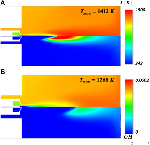
FIGURE 12. Case 13 (a) and 14 (b) (70% H2) temperature and OH fields. Figure (A) refers to dilution with 100% CO2 in vol., figure (B) refers to dilution with 100% H2O in vol.
Numerical simulations of a quasi-industrial flameless combustion chamber have been carried out with different compositions, injector geometries and dilution species in order to assess whether MILD conditions are achievable for a number of different working conditions. Numerical results were first confronted to available experimental temperature measurements at various axial locations in order to validate the CFD model.
The main findings can be summarized as follows:
• In the case of a base injector (16 mm), MILD conditions are achieved for hydrogen content up to 50% in volume depending on the equivalence ratio. More specifically, two equivalence ratios, 0.8 and 1, were tested: even at low H2 levels (30%), MILD conditions are more easily satisfied in stoichiometric conditions and they are preserved for H2 content up to 50%. At 70% H2 level, a conventional flame is developed regardless of the variations of the equivalence ratio.
• Varying the injector geometry has no significant effect in the case of high H2 contents in the mixture. Four different geometries were tested: two 4-holes configuration with different air inlet diameters (9 and 5.4 mm) in order to modify the inlet momentum flux ratio, one 8-holes air inlet (
• Increasing the fuel nozzle length by 25 mm results in a noticeable decrease of the peak temperature; MILD conditions can be observed for up to 75% H2 in vol.
• Fuel dilution with either CO2. or H2O leads to an overall smoothing of the temperature gradients in the combustion chamber, along with decreased OH emissions. In the case of CO2 dilution the maximum temperature decreases to approximately 1400K but a conventional flame is still present. On the other hand, in the case of H2O dilution the temperature field is more homogeneous and the peak temperature further reduces to 1268K.
In conclusion, it is more challenging to operate in MILD conditions for H2 content higher than 50%. Increasing the fuel lance length allows to satisfy the conditions for MILD operation up to a hydrogen content of 75%. This work results suggest that different combinations of fuel inlet length and equivalence ratio φ may lead to flameless conditions in the combustion chamber for a broader range of fuel mixtures. Future works will focus on the determination of these working conditions and their experimental validation.
The raw data supporting the conclusions of this article will be made available by the authors, without undue reservation.
AP, MF, and RA have contributed to the research concept and design. RA and MF provided PaSR results. MF provided the experimental results. RA assembled the data and provided the first version of the paper along with AP. AP and MF critically revised the paper up to the final version.
This project has received funding from the European Research Council (ERC) under the European Union’s Horizon 2020 research and innovation program under grant agreement no. 714605. The first and second authors wish to thank the Fonds de la Recherche Scientifique (FNRS) Belgium for financing their research.
The authors declare that the research was conducted in the absence of any commercial or financial relationships that could be construed as a potential conflict of interest.
Adamczyk, W. P., Bialecki, R. A., Ditaranto, M., Gladysz, P., Haugen, N. E. L., Katelbach-Wozniak, A., et al. (2017). CFD modeling and thermodynamic analysis of a concept of a mild-oxy combustion large scale pulverized coal boiler. Energy 140, 1305–1315. doi:10.1016/j.energy.2017.03.130
Arghode, V. K., and Gupta, A. K. (2010). Effect of flow field for colorless distributed combustion (cdc) for gas turbine combustion. Appl. Energy 87 (5), 1631–1640. doi:10.1016/j.apenergy.2009.09.032
Ayoub, M., Rottier, C., Carpentier, S., Villermaux, C., Boukhalfa, A. M., and Honoré, D. (2012). An experimental study of mild flameless combustion of methane/hydrogen mixtures. Int. J. Hydrogen Energy, 37. 6912–6921. doi:10.1016/j.ijhydene.2012.01.018
Bilger, R. W., Stårner, S. H., and Kee, R. J. (1990). On reduced mechanisms for methaneair combustion in nonpremixed flames. Combust. Flame 80 (2), 135–149. doi:10.1016/0010-2180(90)90122-8
Cavaliere, A., and de Joannon, M. (2004). Mild combustion. Prog. Energy Combust. Sci. 30 (4), 329–366. doi:10.1016/j.pecs.2004.02.003
Choi, G.-M., and Katsuki, M. (2001). Advanced low nox combustion using highly preheated air. Energy Convers. Manag. 42 (5), 639–652. doi:10.1016/S0196-8904(00)00074-1
Chomiak, J. (1990). Combustion a study in theory, fact and application. Hachette, United Kingdom: Abacus Press.
Colorado, A. F., Herrera, B. A., and Amell, A. A. (2010). Performance of a flameless combustion furnace using biogas and natural gas. Bioresour. Technol. 101 (7), 2443–2449. doi:10.1016/j.biortech.2009.11.003
Bowman, C. T., Hanson, D. F. D., Gardiner, W. C., Lissianki, V., Smith, G. P., Golden, D. M., et al. (2006). Gri 2.11 2006.
Dally, B. B., Karpetis, A. N., and Barlow, R. S. (2002). Structure of turbulent non-premixed jet flames in a diluted hot coflow. Proc. Combust. Inst., 29. 1147–1154. doi:10.1016/S1540-7489(02)80145-6
Derudi, M., Villani, A., and Rota, R. (2007). Sustainability of mild combustion of hydrogen-containing hybrid fuels. Proc. Combust. Inst. 31 (2), 3393–3400. doi:10.1016/j.proci.2006.08.107
Duwig, C., Stankovic, D., Fuchs, L., Li, G., and Gutmark, E. (2007). Experimental and numerical study of flameless combustion in a model gas turbine combustor. Combust. Sci. Technol. 180 (2), 279–295. doi:10.1080/00102200701739164
Ferrarotti, M., Amaduzzi, R., Bascherini, D., Galletti, C., and Parente, A. (2020a). Heat release rate markers for the adelaide jet in hot coflow flame. Front. Mech. Eng. 6 (5). doi:10.3389/fmech.2020.00005
Ferrarotti, M., Bertolino, A., Amaduzzi, R., and Parente, A. (2020b). On the Influence of Kinetic uncertainties on the accuracy of numerical modeling of an industrial flameless furnace fired with NH3/H2 blends: a numerical and experimental study. Front. Energy Res. 8:597655. doi:10.3389/fenrg.2020.597655
Ferrarotti, M., Fürst, M., Cresci, E., de Paepe, W., and Parente, A. (2018). Key modeling aspects in the simulation of a quasi-industrial 20 kW moderate or intense low-oxygen dilution combustion chamber. Energy & Fuels 32 (10), 10228–10241. doi:10.1021/acs.energyfuels.8b01064
Galletti, C., Parente, A., and Tognotti, L. (2007). Numerical and experimental investigation of a mild combustion burner. Combust. Flame 151 (4), 649–664. doi:10.1016/j.combustflame.2007.07.016
Galletti, C., Parente, A., Derudi, M., Rota, R., and Tognotti, L. (2009). Numerical and experimental analysis of no emissions from a lab-scale burner fed with hydrogen-enriched fuels and operating in mild combustion. Int. J. Hydrogen Energy 34 (19), 8339–8351. doi:10.1016/j.ijhydene.2009.07.095
Hosseini, S. E., and Mazlan, A. (2013). Biogas flameless combustion: a review. Appl. Mech. Mater. 388, 273–279. doi:10.4028/www.scientific.net/AMM.388.273
International Energy Agency (2017). Key world energy Statistics. Paris, France: International Energy Agency.
Li, Z., Alberto, C., Sadiki, A., and Parente, A. (2017). Comprehensive numerical study of the adelaide jet in hot-coflow burner by means of rans and detailed chemistry. Energy 139, 555–570. doi:10.1016/j.energy.2017.07.132
Li, Z., Ferrarotti, M., Alberto, C., and Parente, A. (2018). Finite-rate chemistry modelling of non-conventional combustion regimes using a partially-stirred reactor closure: combustion model formulation and implementation details. Appl. Energy 225, 637–655. doi:10.1016/j.apenergy.2018.04.085
Magnussen, B. F. (2005). “The eddy dissipation concept: a bridge between science and technology,” in ECCOMAS Thematic Conference on Computational Combustion, Lisbon, Portugal, June 2005.
Minamoto, Y., Swaminathan, N., Cant, R. S., and Leung, T. (2014). Reaction zones and their structure in mild combustion. Combust. Sci. Technol. 186 (8), 1075–1096. doi:10.1080/00102202.2014.902814
Nikolaidis, P., and Poullikkas, A. (2017). A comparative overview of hydrogen production processes. Renew. Sustain. Energy Rev. 67, 597–611. doi:10.1016/j.rser.2016.09.044
Oldenhof, E., Tummers, M. J., van Veen, E. H., and Roekaerts, D. J. E. M. (2011). Role of entrainment in the stabilisation of jet-in-hot-coflow flames. Combust. Flame 158 (8), 1553–1563. doi:10.1016/j.combustflame.2010.12.018
Parente, A., Galletti, C., and Tognotti, L. (2008). Effect of the combustion model and kinetic mechanism on the mild combustion in an industrial burner fed with hydrogen enriched fuels. Int. J. Hydrogen Energy 33 (24), 7553–7564. doi:10.1016/j.ijhydene.2008.09.058
Rafidi, N., and Blasiak, W. (2006). Heat transfer characteristics of hitac heating furnace using regenerative burners. Appl. Therm. Eng. 26 (16), 2027–2034. doi:10.1016/j.applthermaleng.2005.12.016
Sabia, P., de Joannon, M., Fierro, S., Tregrossi, A., and Cavaliere, A. (2007). Hydrogen-enriched methane mild combustion in a well stirred reactor. Exp. Therm. Fluid Sci. 31 (5), 469–475. doi:10.1016/j.expthermflusci.2006.04.016
Smith, T. F., Shen, Z. F., and Friedman, J. N. (1982). Evaluation of coefficients for the weighted sum of gray gases model. J. Heat Tran. 104 (4), 602–608. doi:10.1115/1.3245174
Sorrentino, G., Pino, S., Bozza, P., Ragucci, R., and de Joannon, M. (2019). Low-NOx conversion of pure ammonia in a cyclonic burner under locally diluted and preheated conditions. Appl. Energy 254, 113676. doi:10.1016/j.apenergy.2019.113676
Szegö, G. G., Dally, B. B., and Nathan, G. J. (2008). Scaling of NOx emissions from a laboratory-scale mild combustion furnace. Combust. Flame 154 (1), 281–295. doi:10.1016/j.combustflame.2008.02.001
Wünning, J. A., and Wünning, J. G. (1997). Flameless oxidation to reduce thermal no-formation. Prog. Energy Combust. Sci. 23 (1), 81–94. doi:10.1016/S0360-1285(97)00006-3
Keywords: hydrogen, combustion, moderate or intense low-oxygen dilution combustion, flameless, furnace
Citation: Amaduzzi R, Ferrarotti M and Parente A (2021) Strategies for Hydrogen-Enriched Methane Flameless Combustion in a Quasi-Industrial Furnace. Front. Energy Res. 8:590300. doi: 10.3389/fenrg.2020.590300
Received: 31 July 2020; Accepted: 19 November 2020;
Published: 20 January 2021.
Edited by:
Alfonso Chinnici, University of Adelaide, AustraliaReviewed by:
Yusuf Bicer, Hamad bin Khalifa University, QatarCopyright © 2021 Amaduzzi, Ferrarotti and Parente. This is an open-access article distributed under the terms of the Creative Commons Attribution License (CC BY). The use, distribution or reproduction in other forums is permitted, provided the original author(s) and the copyright owner(s) are credited and that the original publication in this journal is cited, in accordance with accepted academic practice. No use, distribution or reproduction is permitted which does not comply with these terms.
*Correspondence: Alessandro Parente, YWxlc3NhbmRyby5wYXJlbnRlQHVsYi5iZQ==
Disclaimer: All claims expressed in this article are solely those of the authors and do not necessarily represent those of their affiliated organizations, or those of the publisher, the editors and the reviewers. Any product that may be evaluated in this article or claim that may be made by its manufacturer is not guaranteed or endorsed by the publisher.
Research integrity at Frontiers

Learn more about the work of our research integrity team to safeguard the quality of each article we publish.