
94% of researchers rate our articles as excellent or good
Learn more about the work of our research integrity team to safeguard the quality of each article we publish.
Find out more
ORIGINAL RESEARCH article
Front. Energy Res. , 29 September 2020
Sec. Sustainable Energy Systems
Volume 8 - 2020 | https://doi.org/10.3389/fenrg.2020.553295
This article is part of the Research Topic Advances and Challenges in Ocean Wave Energy Harvesting View all 8 articles
 Bin-zhen Zhou1,2Jian-jian Hu2Ke Sun2*Yingyi Liu3Maurizio Collu4
The heaving wave energy converter (WEC) is one typical type of point absorber WECs with high energy conversion efficiency but significantly affected by the viscous effect. It is widely known that the bottom shape of such WECs plays an important role in influencing the viscosity, so a detailed qualitative investigation is essential. Here a numerical study is performed for the influence of bottom shape on motion response and energy conversion performance of a heaving WEC. The numerical model is developed based on the potential flow theory with a viscous correction in the frequency domain. Cylindrical WECs with flat, cone, and hemispherical bottoms and the same displacement are considered. WECs with larger diameter-to-draft ratios (DDRs) are found to experience a relatively smaller viscous effect and achieve effective energy conversion in a broader frequency range. With the same DDR, the flat bottom has the most considerable viscous effect, following by the cone bottom with conical angles 90° and the hemispherical bottom. When the DDR is relatively small, the hemispherical bottom had the best energy conversion performance. Similarly, when the DDR is relatively large, the energy conversion performance of the floater with a hemispherical bottom and a cone bottom with 90° is better, while that with the flat bottom is the worst.
Wave energy is amongst the ocean renewable energies with huge reserves. Wave energy converters (WECs) based on different mechanisms to extract energy from water waves have been invented (de O. Falcão, 2010). In general, WECs can be categorized into oscillating water columns, point absorbers, overtopping systems, and bottom-hinged systems based on their working principle (Li and Yu, 2009). The oscillating water columns, as a promising type of wave energy device, has been widely investigated by analytical (He et al., 2019), numerical (Wang et al., 2018) and experimental (He et al., 2013; Ning et al., 2019) methods. The point absorber wave energy converter (PA-WEC) is convenient for array arrangement due to its small dimension relative to the incident wavelength. It is thought to be the most efficient type in terms of the wave power conversion per unit volume (Li and Yu, 2009; McCabe and Aggidis, 2009). However, the high construction cost and the low energy conversion efficiency make the electricity generated by WECs less competitive. Therefore, it is necessary to improve the energy conversion efficiency of WECs to make wave energy economically competitive.
One typical type of PA-WECs works solely in the heave mode, which receives mechanical power resulting from the heave motion and generates electricity by the power take-off (PTO) system. Axial-symmetrical floaters are normally adopted to reduce the sensibility to the wave direction, such as Wavebob (Ireland) (Weber et al., 2009), PowerBuoy (USA) (Edwards and Mekhiche, 2014), and CETO (Australia) (Penesis et al., 2016). The hydrodynamic performance of PA-WECs needs to be studied in detail to maximize the wave power absorption, where the geometrical optimization is an important way. Generally, there are four types of methods to solve the hydrodynamic characteristics of a PA-WEC: analytical method, boundary element method, computational fluid dynamics (CFD) method, and experimental method. A comprehensive review can be found in Li and Yu (2009).
Previous studies were primarily focused on the impact of the shape of the bottom of the WEC on its energy conversion efficiency, for a specific size or considering some main parameters. The previous investigations have covered only some of the aspects, and knowledge gaps in the fields still exists. Most of the previous numerical simulations were carried out adopting a potential flow theory (PFT) approach without considering the viscous effects, which allows an initial understanding of the hydrodynamic fundamentals of WECs with different bottom shapes. De Backer (2009) compared the hydrodynamic performance and power absorption of cylinders with a conical bottom with an apex angle of 90° and a hemisphere bottom in irregular waves, showing that the cone-cylinder performs slightly better than the hemisphere-cylinder shape. Zhang et al. (2016) used a semi-analytical method in investigating the energy conversion efficiency of four floaters with different bottom shapes, including cylindrical, hemispherical, paraboloidal, and conical, with the same displacement. Zhang et al. (2016) suggested that the cylindrical type had fantastic wave energy conversion ability at some given frequencies, whereas in random sea waves, the parabolic and conical ones had better stabilization and applicability in wave power conversion. Khojasteh and Kamali (2016) found that the cone-cylinder shape slightly performed better than the hemispherical cylinder via numerical simulations based on the linear potential theory. Shi et al. (2019) compared the optimal average capture width ratio (CWR) of five types of geometry with the same mass based on the linear potential theory without viscous correction, including flat-bottom, cone-bottom, hemisphere-bottom, linear-chamfered, and circular-chamfered cylinders, showing that the flat-bottom cylinder was the best and the hemisphere-bottom cylinder was the worst. However, the ignorance of viscous effects may lead to incomplete conclusions. Especially when it is around the resonance frequency, the response simulated by non-viscous linear PFT could be 10 times or much larger than that of the experiment (Tom, 2013). An alternative approach is to use the CFD method, which can deal with strongly-nonlinear phenomena, such as vortex shedding and turbulence. Zhang et al. (2015) studied the effect of buoy shape on wave energy conversion using CFX (Computational Fluid Dynamics X) and found that the response of the circular truncated cone buoy preceded the cylindrical buoy. Jin and Patton (2017) studied three cylindrical floaters by LS-DYNA (LS-dynamic finite element analysis), and the results demonstrated that the rounded- and conical-bottom floaters had less viscous damping than that with the flat-bottom. Zhang et al. (2020a) selected four single-floater integrated systems with different bottom shapes and studied the effect of bottom shape on the hydrodynamic performance of the integrated system.
However, the computational cost of detailed CFD simulations is high, partly due to the requisite large computational meshes. In this regard, the PFT with a viscous correction provides a tractable way to conduct an initial optimization design, which can be further refined by a detailed CFD study of selected cases. There are many different ways to provide the viscous correction. Bacelli et al. (2013) applied a force linearly proportional to the velocity as the equivalent viscous drag term in the frequency-domain equation, where an iterative procedure was necessary because of the correlation of the viscous coefficient and the body velocity. The numerical and experimental studies of Tom (2013) and Son et al. (2016) on a heaving point absorber WEC illustrated that the linear PFT could well predict the exciting forces. In contrast, the radiation forces (especially the damping term) were significantly affected by viscous effects. Chen et al. (2018b) showed that the viscous effect of added mass was much smaller than that of radiation damping. The experimental results of Tom (2013) showed that the viscous effect did not change obviously with the wave frequency. Therefore, the viscous correction of the hydrodynamic coefficients of the floater at the natural frequency can meet the calculation requirements. The viscous hydrodynamic coefficients can be obtained from the experiment (Chen et al., 2018a; Lee et al., 2018) or CFD simulation (Chen et al., 2018b) of the free decay test.
It is not possible to generalize the effect of the bottom shape of cylindrical PA-WECs with different diameter-to-draft ratios (DDRs) on the motion response and energy conversion performance from the existing studies. The motivation and novelty of this work are two-fold: 1) developing an efficient method for accurate prediction of the hydrodynamic performance of PA-WECs using a viscous-corrected linear potential theory, 2) understanding comprehensively the influence of the bottom shape of cylindrical PA-WECs on the motion response and energy conversion performance. This will help reduce the overall cost of wave energy harvesting.
The paper is structured as follows. Mathematical Model section introduces the mathematical model of a single heaving WEC based on PFT with a viscous correction in the frequency domain. Convergence Study and Validation section presents the convergence study and the validation of the numerical model. The hydrodynamic performance and the CWR of a cylindrical WEC with flat bottom, cone bottom and hemispherical bottom are studied in sections Motion Response and Capture Width Ratio of a Cylindrical Wave Energy Converter With Different Bottom Shapes, Effect of Bottom Shapes on Motion Response and Capture Width Ratio, and Conclusions, respectively. The effects of bottom shape on the motion response and the CWR are analyzed. Finally, the conclusions are presented.
Based on the linear frequency-domain PFT, the motion equation of a single WEC in heave mode can be written as
where m is the mass of the WEC; ω is the wave frequency; i is the imaginary unit; z3 is the heave motion of the WEC; C33, k33,bpto, and Fex,3 are the restoring force, the elastic stiffness, mechanical damping due to PTO system, and the wave exciting force in the heave mode, respectively; μ33 and λ33 are the added mass and radiation damping of the WEC in the heave mode due to the heave motion of the WEC based on the PFT, respectively; λvis,3 is the corrected viscous damping of the WEC in the heave mode at the natural frequency. μ33, λ33 and Fex,3 are calculated by a higher-order boundary element method program WAFDUT (Teng and Taylor, 1995). WAFDUT is used to solve the diffraction and radiation problems of floating body with arbitrary shapes based on the linear PFT in frequency domain. More applications of the program can be found in Teng et al. (2014).
The corrected viscous damping λvis,3 can be obtained through the free decay motion of the floater. The non-dimensional damping κ is given by Lee et al. (2018)
where
where C33 and ωn are the hydrostatic coefficient and the natural frequency, respectively. The overall hydrodynamic damping, including the potential and the viscous parts, can be estimated from the decaying oscillation by determining the ratio between any pair of successive (double) amplitudes. In the present paper, the first three pairs are selected to obtain the average value.
The viscous damping correction coefficient of the WEC is
The non-dimensional linearized viscous damping correction is defined as
where
The heave motion of WEC can be obtained from Eq. 1, i.e.,
The wave power P(ω) at wave frequency ω produced by the WEC is derived by
The CWR of the WEC CW can be defined as
where 2r is the width of the WEC, PW is the mean incident wave power transportation of a regular wave per unit wave crest, i.e.,
where H is the incident wave height, h is the water depth, k is the wavenumber.
Optimization of the PTO parameters can be classified into two methods (Folley, 2016). One is double-variable optimization, involving the elastic stiffness k33 and the damping boot; the other is one-variable optimization, considering only the damping boot while remaining the elastic stiffness a constant. The first method is to keep the WEC resonance at any wave frequencies, which is not easy to realize in practical cases if the spring mechanism always needs to be changed. In the present paper, the elastic stiffness k33 is considered as zero, and the second method is used. The optimal damping coefficient of the WEC boot at a wave frequency ω can be derived as the maximum wave power P(ω) is obtained (Sun et al., 2018).
As introduced in Motion Equation of Wave Energy Converter section, the total damping λvist,3 can be obtained through the free decay motion of the WEC, simulating using the Star-CCM+ (need a reference). Star-CCM+ has been used in studying the interaction of waves and a two-dimensional floating body (Zhang et al., 2020a; Zhang et al., 2020b), and the free decay motion of a three-dimensional floater (Chen et al., 2018b). Their accuracy has been validated with the experimental results. The detailed setup can be found in Zhang et al. (2020a; 2020b) and Chen et al. (2018b).
To further verify the accuracy of simulating the interaction between waves and a three-dimensional floating body, the experiment of a floating cylindrical floater with the flat bottom in waves by Shi et al. (2019) is simulated, where the radius of the cylinder buoy was 0.4 m, the height of the buoy was 0.4 m, the draft of the buoy was 0.12 m, the wave height was 0.2 m, and the wave period was 2 s. In the experiment, three degrees of freedom, including surge, heave, and pitch motions, were considered. The results showed that the heave motion did not interact with the surge and the pitch motions. Therefore, only the heave motion of the floater is considered in the present CFD simulation. Figure 1A compares the heave motion between the CFD results calculated by Star-CCM+ and the experiment by Shi et al. (2019). The overall agreement with the published experimental data verifies that the present CFD model in the accurate prediction of the interaction of waves with a three-dimensional floater.
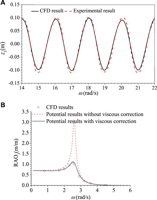
Figure 1. Comparison of heave motion between the CFD results with other results. (A) Comparison of the heave motion between the present CFD result and the experiment result (Shi et al., 2019). (B) Comparison of RAO in the heave mode between the CFD results and the PFT results with and without viscous correction.
Although the CFD results can predict the experimental results accurately, the CPU cost is exceedingly high. The PFT with a viscous correction is an accurate and fast way to predict the motion of a WEC. The flat bottom cylindrical WEC with draft d = 1.0 m and radius r = 0.8 m is taken as an example to validate its accuracy further. The wave height H is 0.2 m. The optimal PTO damping based on Eq. 10 is considered. The RAOs (Response Amplitude Operator) of the heave motion calculated by the direct CFD method and the PFT with and without viscous correction are compared in Figure 1B, showing that the potential-theory results without viscous correction overestimate greatly the heave motion near the resonant frequency ω = 2.5 rad/s, but the PFT results with viscous correction agree well with the direct CFD results. Therefore, the viscous-corrected PFT is applied in the following results.
In the following sections, different DDRs of 2r/d are chosen, where d = 1.0 m. The investigation of Hu et al. (2020) showed that fλ,vist generally decreased to approach 1.0 as the ratio 2r/d increased. It meant that the viscous effect became smaller as the WEC became fatter, such that the viscous effect of a very fat floater is negligible. This can be explained by the KC number. The KC number means the ratio of the viscous force and inertial force. It can be simplified as KC = VT/L, where V is the amplitude of the oscillation of the body, T is the period of oscillation, and L is a characteristic length. For the cylinder, the diameter is the characteristic length. As the diameter increases, the KC number decreases, which means the effect of the viscous force becomes smaller compared with the inertial force.
Figures 2A,B show the variation of the heave RAO against the wave frequency for the flat bottom cylindrical WEC with different DDRs of 2r/d = 0.8, 1.6, 2.4, 2.8, 3.2, 3.6 based on the PFT without and with viscous correction, respectively. The stiffness k33 = 0, and the optimal PTO damping calculated by Eq. 10 are considered for all cases. Figures 2A,B show that as the wave frequency ω < 2.0 rad/s, the RAO for different 2r/d all tends to 0.7 and increases to a peak value near the natural frequency of the WEC, and then decreases to zero as the wave frequency continues to increase. The above trend is similar in both methods, but the peak value of RAO is significantly reduced by considering viscous correction for the smaller 2r/d. It is because that the viscous damping correction coefficient fλ,vist increases as the WEC becomes thinner. The potential results overestimate the RAO significantly near the resonance frequency. The maximum magnification factor of the RAO is 5.4 for the thinnest WEC 2r/d = 0.8, while 1.4 for the fattest WEC 2r/d = 3.6, where the magnification factor is defined as the ratio between the PFT (only) results and the results obtained by the PFT approach with viscous correction.
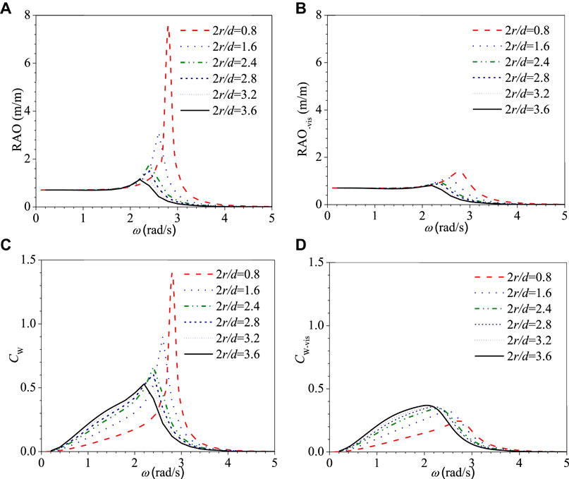
Figure 2. Variation of heave RAO and CWR CW vs. ω for the flat bottom cylindrical WEC with different 2r/d. (A) RAO, (B) RAO-vis, (C) CW, and (D) CW-vis.
The corresponding CWRs CW are shown in Figures 2C,D. It is demonstrated from Figure 2C that the CWR CW increases with the increase of 2r/d in the low wave frequency region, but decreases in the high wave frequency region. Figure 2C also shows that the peak value of CW decreases with the increase of 2r/d, while it increases by considering the viscous correction, as shown in Figure 2D. The viscous damping correction has a great influence on the thinner WEC near the resonance frequency, which significantly reduces the CWR CW. The maximum magnification factor of CW is 5.6 for the thinnest WEC 2r/d = 0.8, while 1.4 for the fattest WEC 2r/d = 3.6. Figure 2D shows that for the larger 2r/d, not only the peak value of CW is larger, but also the frequency range of the high power captured is broader, that is, the effective frequency-domain width is larger. Figures 2B,D show the CWR CW is larger at most of the frequencies for the fatter WEC, even the RAO is smaller, which is better for the design of WEC due to the smaller required reserved movement stroke. It means that in a limited region, the fatter WECs will capture more wave energy. Nevertheless, if the viscous effect is neglected, the contrary conclusions are obtained.
The conical bottom is usually used to reduce the viscous effect as a comparison to the flat bottom. Figure 3 shows the schematic diagram of the submerged part of the conical-bottom cylindrical WEC. The WEC with different DDRs (2r/d = 1.6, 2.8, 3.6) and conical angles (α = 90°, 120°, 150°, 180°) are considered to study the hydrodynamic performance and energy conversion capacity. The submerged part under the mean water line consists of two parts: one is the vertical cylindrical part with the height of d1 and the other is the non-flat bottom part with the height of d2. To study the effect of the conical angle, the displacements (or massed) are taken as the same for floaters with different conical angles. The equivalence drafts d are kept as 1.0. Therefore, d1 and d2 of different conical angels can be calculated as
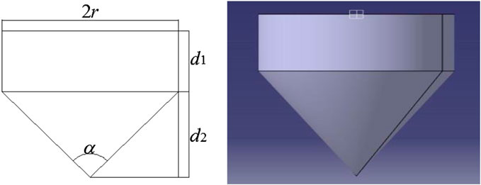
Figure 3. Schematic diagram of the submerged part of the conical-bottom cylindrical WEC.
Table 1 shows the dimension parameters and viscous correction coefficients of the conical bottom cylindrical WEC with different DDRs and conical angels. It can be seen that for the same DDR 2r/d, the viscous correction coefficient decreases with the decrease of the conical angel, which is the same as Chen et al. (2018b). Besides, for the same conical angle, the viscous correction coefficient decreases with the increase of 2r/d, similar to the flat bottom WEC.
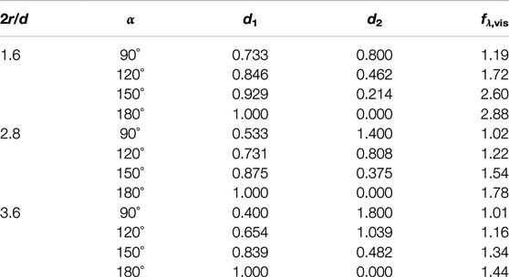
TABLE 1. Dimension parameters and viscous correction coefficients of conical bottom cylindrical WEC.
Figures 5A–E show the variations of the RAO of the heave motion against the wave frequency for the conical-bottom cylindrical WEC with different DDRs of 2r/d = 1.6, 2.8, 3.6 and different conical angels of α = 90°, 120°, 150°, 180° based on the PFT without and with viscous correction, respectively. The corresponding CWRs are shown in Figures 4A–E. Figures 5 and 4A,C,E show that the RAO and the CWR of WECs are both smaller for the smaller conical angle near the resonance frequency for the PFT results. Figures 5 and 4B,D,F show that when the viscous effect is considered, the RAO and the CWR of WECs mainly change at the resonance frequency. Because the viscous correction coefficient with a larger cone angle is larger, the peak value of the RAO and the CWR decreases significantly. In the low-frequency region, the CWRs are close for different conical angles. At the resonance frequency and in the high-frequency region, the smaller the conical angle is, the larger the CWR is. Therefore, the smaller the cone angle is, the more extensive the frequency range of the high power captured is. Figures 5B,D,F show that when 2r/d is small (2r/d = 1.6 and 2.8), the smaller the conical angle is, the larger the peak value of RAO is, therefore, the broader range movement stroke needs to be reserved in the design of WEC. When 2r/d is large (2r/d = 3.6), the peak value of RAO of different conical angles are very close, and even the smaller the conical angle is, the smaller the peak value of RAO is, which is better for the engineering design. It means that the WEC with a larger 2r/d and a smaller conical angel has a better energy capture performance at different wave frequencies.
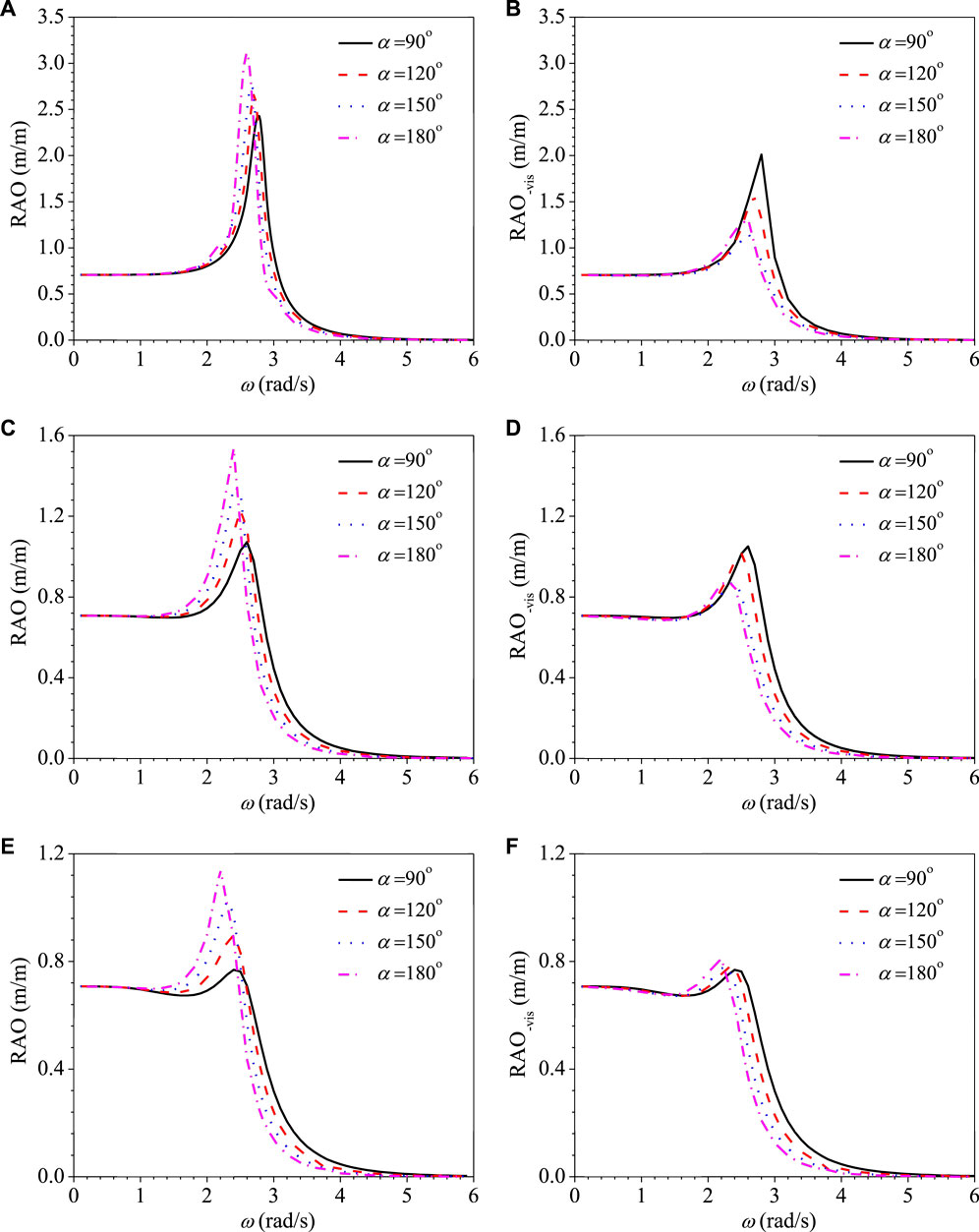
FIGURE 4. Variations of RAO vs. ω for the cone bottom cylindrical WEC with different 2r/d. (A) RAO at 2r/d = 1.6, (B) RAO-vis at 2r/d = 1.6, (C) RAO at 2r/d = 2.8, (D) RAO-vis at 2r/d = 2.8, (E) RAO at 2r/d = 3.6, and (F) RAO-vis at 2r/d = 3.6.
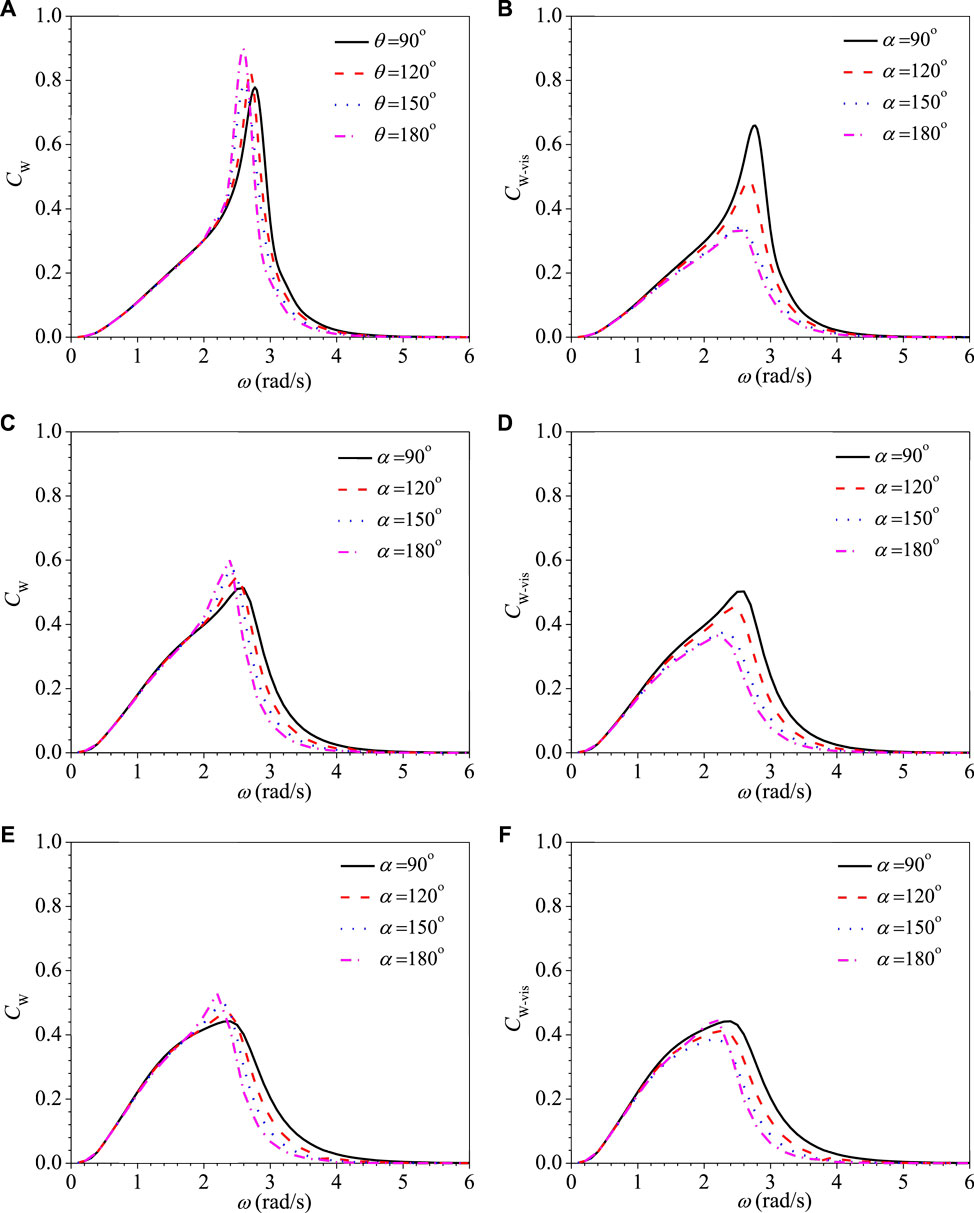
Figure 5. Variations of CWR CW vs. ω for the cone bottom cylindrical WEC with different 2r/d. (A) CW at 2r/d = 1.6, (B) C W-vis at 2r/d = 1.6, (C)CW at 2r/d = 2.8, (D) CW-vis at 2r/d = 2.8, (E) CW at 2r/d = 1.6, and (F) CW-vis at 2r/d = 1.6.
The hemispherical bottom is also a good bottom shape to reduce the viscous effect comparing with the flat bottom. Figure 6 shows the schematic diagram of the submerged part of the hemispherical bottom cylindrical WEC. The WEC with different DDRs of 2r/d = 0.8, 1.6, 2.4 and 2.8. The equivalence drafts d are still kept as 1.0, so the height of the submerged vertical cylindrical part d0 can be calculated by
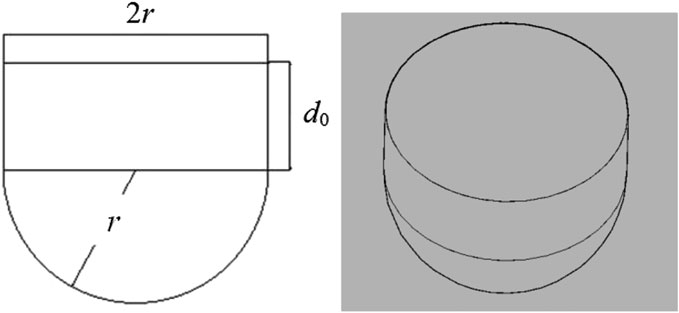
Figure 6. Schematic diagram of submerged part of hemispherical bottom cylindrical WEC.
Table 2 shows the dimension parameters and the viscous correction coefficients of the hemispherical bottom cylindrical WEC with different 2r/d. It can be seen that the viscous correction coefficients all tend to 1.0 even for the smallest 2r/d = 0.8. It means that the viscous effect of the hemispherical bottom cylindrical WEC is much smaller than the flat and the conical ones for the smaller 2r/d.
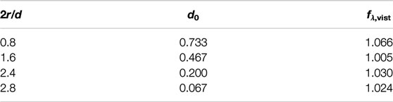
TABLE 2. Dimension parameters and viscous correction coefficients of hemispherical bottom cylindrical WEC.
Figures 7A,B show the variation of the heave RAO and the CWR CW against the wave frequency for the hemispherical bottom cylindrical WEC with different DDRs of 2r/d = 0.8, 1.6, 2.4 and 2.8 based on the PFT without viscous correction, respectively. It can be seen from Figure 7A that as the wave frequency ω < 2.0 rad/s, the RAO for different 2r/d all tends to 0.7, then increases to a maximum near the natural frequency, and decreases to zero as wave frequency continues to increase, similar to the flat bottom, as shown in Figure 2A. Figure 7A also shows that the peak value and the value in the high-frequency region of RAO decrease as 2r/d increases. Figure 7B shows that the peak value of the CWR CW decreases with the increase of 2r/d, but it increases in the low-frequency region ω < 2.5 rad/s. Although the peak value of the capture width is smaller near the resonance frequency for the larger 2r/d, the frequency range of the high capture width is more extensive, that is, the effective width in the frequency domain is broader. Meanwhile, the smaller range of movement stroke needs to be reserved in the design of WEC. Therefore, if the wave condition is always invariable, the smaller 2r/d is better. However, the wave condition in the practical sea area is variable, the larger 2r/d may be better. However, it depends on the detailed wave condition.
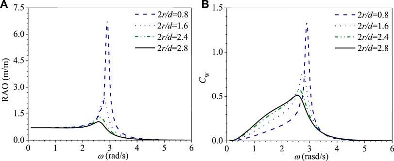
Figure 7. Variations of heave RAO and CWR CW vs. ω of hemisphere bottom cylindrical WEC with different 2r/d. (A) RAO. (B) CWR.
To study the effect of bottom shape on the energy conversion performance of floaters, the floaters with the flat bottom, the cone bottom with conical angles 90°, and the hemispherical bottom are compared. The displacements are kept the same, i.e., the equal draft d is similar for the same diameter 2r. Table 3 shows the total damping considering the viscous effect, the radiation damping based on the potential theory, and the viscous correction coefficients of floaters with different bottom shapes, where three different DDRs of 2r/d = 1.6, 2.4, and 2.8 are taken as examples. Similar to the above conclusion, the viscous damping correction coefficient decreases with the increase of 2r/d for the same bottom. For the same 2r/d, the viscous damping correction coefficients of the floater with the flat bottom is the biggest, followed by the cone bottom with conical angles 90° and the hemispherical bottom.
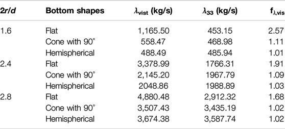
TABLE 3. Damping and the viscous correction coefficients of floaters with different bottom shapes.
Figures 8A–C show the variation of the RAO of the heave motion against the wave frequency for three different bottom cylindrical WEC with different DDRs of 2r/d = 1.6, 2.4, and 2.8 based on the PFT with viscous correction, respectively. The corresponding CWRs are shown in Figure 9. For 2r/d = 1.6, the RAO and the CWR of floaters with the hemispherical bottom are the biggest, followed by the cone bottom with 90° and the flat bottom. For 2r/d = 2.4 and 2.8, the RAO and the CWR of floaters with the cone bottom with 90° and the hemispherical bottom are both similar over the entire wave frequency range, and the value of them with the flat bottom is smaller since the wave frequency is larger than the natural frequency. That is to say, as the DDR 2r/d is relatively small, the hemispherical bottom has the best energy conversion performance because of its smallest viscous dissipation. The energy conversion performance of floater with a hemispherical bottom and a cone bottom with 90° is similar, while that with a flat bottom is the worst as 2r/d is relatively large.

Figure 8. Variations of RAO versus ω with different bottom shapes based on PFT with viscous correction. (A) 2r/d = 1.6. (B) 2r/d = 2.4. (C) 2r/d = 2.8.
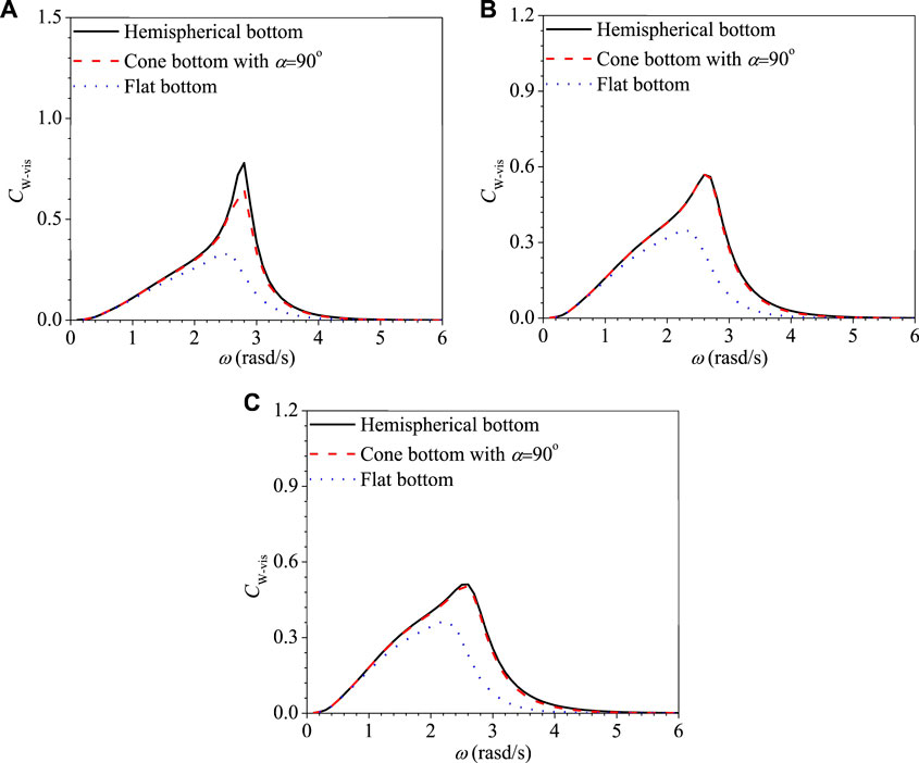
Figure 9. Variations of CWR Cw versus ω with different bottom shapes based on PFT with viscous correction. (A) 2r/d = 1.6. (B) 2r/d = 2.4. (C) 2r/d = 2.8.
In this study, the linear PFT in the frequency domain is presented to investigate the hydrodynamic and energy conversion performances of the cylindrical WEC with the flat, cone, and hemispherical bottoms. The viscosity effect that is ignored by the PFT is corrected, and the ten-folded overestimation of the motion response is reduced to a quite reasonable level. Further, the viscous correction is quantified for a large range of bottom shapes and dimensions. The following conclusions can be drawn from this study:
(1) The viscous effect becomes smaller as the radius of the cylindrical WEC increases. With the same DDR, the viscous damping correction coefficients of the floater with a flat bottom is the biggest, followed by a cone bottom with conical angles 90° and a hemispherical bottom.
(2) For the WEC with a cone bottom, the larger DDR and the smaller conical angel lead to better energy capture performance at different wave frequencies. The smaller the conical angle is, the smaller the peak value of RAO is. Therefore, the smaller range movement stroke needs to be reserved in the design of WEC, which is better for the engineering design.
(3) For the WEC with a hemispherical bottom, the peak value of the CWR decreases as the DDR increases, but the frequency range of the high power capture is wider and the smaller range movement stroke needs to be reserved in the design of WEC. Therefore, if the wave condition is always invariable, the smaller DDR is better. However, the wave condition in the practical sea area is variable, the larger DDR may be better.
(4) When the DDR is relatively small, the hemispherical bottom has the best energy conversion performance. Similarly, when the DDR is relatively large, the energy conversion performance of floater with a hemispherical bottom and a cone bottom with 90° is better, while that with a flat bottom is the worst.
The original contributions presented in the study are included in the article, further inquiries can be directed to the corresponding author/s.
BZ developed the concept, designed the research work, and wrote the manuscript. JH performed numerical analysis and data processing. KS provided guidance and advice on the research. YL and MC revised the manuscript.
This work was supported by the Natural Science Foundation of China (NSFC) through grant 51761135013, INNO-MPP project, the UK Engineering and Physical Sciences Research Council UK (EPSRC) and the Natural Environment Research Council UK (NERC), through grant EP/R007497/1, the Open Fund of Shandong Provincial Key Laboratory of Ocean Engineering, the High-tech Ship Research Projects Sponsored by Ministry of Industry and Information Technology of the People's Republic of China-Floating Support Platform Project (the second stage) (MIIT201622).
The authors declare that the research was conducted in the absence of any commercial or financial relationships that could be construed as a potential conflict of interest.
Bacelli, G., Balitsky, P., and Ringwood, J. V. (2013). Coordinated control of arrays of wave energy devices-benefits over independent control. IEEE Trans. Sustain. Energy 4, 1091–1099. doi:10.1109/tste.2013.2267961
Chen, Z. F., Zhou, B. Z., Zhang, L., Li, C., Zang, J., Zheng, X., et al. (2018a). Experimental and numerical study on a novel dual-resonance wave energy converter with a built-in power take-off system. Energy 165, 1008–1020. doi:10.1016/j.energy.2018.09.094
Chen, Z. F., Zhou, B. Z., Zhang, L., Zhang, W. C., Wang, S. Q., and Zang, J. (2018b). Geometrical evaluation on the viscous effect of point-absorber wave-energy converters. China Ocean Eng. 32, 443–452. doi:CNKI:SUN:CHIU.0.2018-04-007
De Backer, G. (2009). Hydrodynamic design optimization of wave energy converters consisting of heaving point absorbers. Ghent, Belgium:Department of Civil Engineering, Ghent University.
de O. Falcão, A. F. (2010). Wave energy utilization: a review of the technologies. Renew. Sust. Energy Rev. 14, 899–918. doi:10.1016/j.rser.2009.11.003
Edwards, K. A., and Mekhiche, M. (2014). Ocean power technologies powerbuoy®: system‐level design, development and validation methodology. San Francisco, CA:OMAE.
Folley, M. (2016). Numerical modelling of wave energy converters: state-of-the-art techniques for single devices and arrays. Cambridge, MA: Academic Press.
He, F., Huang, Z. H., and Law, A. W.-K. (2013). An experimental study of a floating breakwater with asymmetric pneumatic chambers for wave energy extraction. Appl. Energy 106, 222–231. doi:10.1016/j.apor.2017.06.009
He, F., Zhang, H. S., Zhao, J. J., Zheng, S. M., and Iglesias, G. (2019). Hydrodynamic performance of a pile-supported OWC breakwater: an analytical study. Appl. Ocean Res. 88, 326–340. doi:10.1016/j.apor.2019.03.022
Hu, J., Zhou, B., Vogel, C., Liu, P., Willden, R., and Sun, K. (2020). Optimal design and performance analysis of a hybrid system combing a floating wind platform and wave energy converters. Appl. Energy 269, 114998. doi:10.1016/j.apenergy.2020.114998
Jin, S., and Patton, R. (2017). “Geometry influence on hydrodynamic response of a heaving point absorber wave energy converter,” in European Wave and Tidal Energy Conference, Southampton, UK.
Khojasteh, D., and Kamali, R. (2016). Evaluation of wave energy absorption by heaving point absorbers at various hot spots in Iran seas. Energy 109, 629–640. doi:10.1016/j.energy.2016.05.054
Lee, H., Poguluri, S., and Bae, Y. (2018). Performance analysis of multiple wave energy converters placed on a floating platform in the frequency domain. Energies 11, 406. doi:10.3390/en11020406
Li, Y., and Yu, Y. H. (2012). A synthesis of numerical methods for modeling wave energy converter-point absorbers. Renew. Sust. Energy Rev. 16, 4352–4364. doi:10.1016/j.rser.2011.11.008
McCabe, A. P., and Aggidis, G. A. (2009). Optimum mean power output of a point-absorber wave energy converter in irregular waves. P. I. Mech. Eng. A.-J. Pow. 223, 773–781. doi:10.1243/09576509JPE751
Ning, D. Z., Wang, R. Q., Chen, L.F., and Sun, K. (2019). Experimental investigation of a land-based dual-chamber OWC wave energy converter. Renew. Sust. Energy Rev. 105, 48–60. doi:10.1016/j.rser.2019.01.043
Penesis, I., Manasseh, R., Nader, J. R., De Chowdhury, S., and Fleming, A. (1998). “Performance of ocean wave-energy arrays in Australia,” in 3rd Asian wave and tidal energy conference, Marina Bay Sands, Singapore, October 25‐27.
Shi, H., Huang, S., and Cao, F. (2019). Hydrodynamic performance and power absorption of a multi-freedom buoy wave energy device. Ocean. Eng.. 172, 541–549. doi:10.1016/j.oceaneng.2018.12.005
Son, D., Belissen, V., and Yeung, R. W. (2016). Performance validation and optimization of a dual coaxial-cylinder ocean-wave energy extractor. Renew. Energy 92, 192–201. doi:10.1016/j.renene.2016.01.032
Sun, S.-y., Sun, S.-l., and Wu, G.-x. (2018). Fully nonlinear time domain analysis for Hydrodynamic performance of an oscillating wave surge converter. China Ocean Eng. 32, 582–592. doi:10.1007/s13344-018-0060-7
Teng, B., Gou, Y., Wang, G., and Cao, G. (2014). “Motion response of hinged multiple floating bodies on local seabed,” in Proceedings of the 24th International Society of Offshore and Polar Engineers, Busan, Korea, June 15‐20.
Teng, B., and Taylor, R. E. (1995). New higher-order boundary element methods for wave diffraction/radiation. Appl. Ocean Res. 17, 71–77. doi:10.1016/0141-1187(95)00007-N
Tom, N. M. (2013). Design and control of a floating wave-energy converter utilizing a permanent magnet linear generator. Ph.D. thesis. Berkeley, CA: University of California
Wang, R. Q., Ning, D. Z., Zhang, C. W., Zou, Q. P., and Liu, Z. (2018). Nonlinear and viscous effects on the hydrodynamic performance of a fixed OWC wave energy converter. Coast. Eng. 131, 42–50. doi:10.1016/j.coastaleng.2017.10.012
Weber, J., Mouwen, F., Parish, A., and Robertson, D. (2009). “Wavebob—research & development network and tools in the context of systems engineering,” in Proceedings of the eighth European wave and tidal energy conference, Uppsala, Sweden, September 7‐10.
Zhang, H., Zhou, B., Vogel, C., Willden, R., Zang, J., and Geng, J. (2020a). Hydrodynamic performance of a dual-floater hybrid system combining a floating breakwater and an oscillating-buoy type wave energy converter. Appl. Energy 259, 114212. doi:10.1016/j.apenergy.2019.114212
Zhang, H., Zhou, B., Vogel, C., Willden, R., Zang, J., and Zhang, L. (2020b). Hydrodynamic performance of a floating breakwater as an oscillating-buoy type wave energy converter. Appl. Energy 257, 113996. doi:10.1016/j.apenergy.2019.113996
Zhang, L., Guo, W., and Wang, S. Q. (2015). Hydrodynamic performance optimization of a point absorber. J. Harbin Inst. Technol. 47, 117–121. doi:10.11918/j.issn.0367-6234.2015.07.019
Keywords: wave energy converter, bottom shape, wave power, energy conversion, viscous correction
Citation: Zhou B, Hu J, Sun K, Liu Y and Collu M (2020) Motion Response and Energy Conversion Performance of a Heaving Point Absorber Wave Energy Converter. Front. Energy Res. 8:553295. doi: 10.3389/fenrg.2020.553295
Received: 18 April 2020; Accepted: 25 August 2020;
Published: 29 September 2020.
Edited by:
Joni Jupesta, SMART Research Institute (SMARTRI), Smart Agribusiness and Food, IndonesiaReviewed by:
Nataliia Sergiienko, University of Adelaide, AustraliaCopyright © 2020 Zhou, Hu, Sun, Liu and Collu. This is an open-access article distributed under the terms of the Creative Commons Attribution License (CC BY). The use, distribution or reproduction in other forums is permitted, provided the original author(s) and the copyright owner(s) are credited and that the original publication in this journal is cited, in accordance with accepted academic practice. No use, distribution or reproduction is permitted which does not comply with these terms.
*Correspondence: Ke Sun, c3Vua2VAaHJiZXUuZWR1LmNu
Disclaimer: All claims expressed in this article are solely those of the authors and do not necessarily represent those of their affiliated organizations, or those of the publisher, the editors and the reviewers. Any product that may be evaluated in this article or claim that may be made by its manufacturer is not guaranteed or endorsed by the publisher.
Research integrity at Frontiers
Learn more about the work of our research integrity team to safeguard the quality of each article we publish.