 Jian Zhou
 Yanwei Yue2
 Zhaoming Meng
- 1Fundamental Science on Nuclear Safety and Simulation Technology Laboratory, Harbin Engineering University, Harbin, China
- 2Research and Development Center, China Nuclear Power Engineering Co., Ltd., Beijing, China
Passive containment cooling system (PCCS) is widely applied in a new generation of nuclear power plants. The initial heat exchanger is the most improtant heat transfer device in the PCCS. Past studies show that the flow distribution has a great influence on the heat transfer performance of a heat exchanger. And a lot of work has been done on improving the flow distribution uniformity of the heat exchanger such as the geometry modification, proper choice of the geometry parameters. However, little work has been done on the tube arrangement. For a heat exchanger applied in the industry, the number of tubes are huge, and it is unrealistic to arrange all the tubes in a row on the one side of the heat exchanger. Therefore, more work should be paid on the influence of the tube arrangement on the flow distribution in the heat exchanger. The present study numerically investigated the effect of the tube arrangement on the flow distribution in a Central-type parallel heat exchanger. Six different kinds of tube arrangement have been investigated on the flow distribution and the pressure loss characteristics of the heat exchanger. The obtained results show that the tube arrangement has a great influence on the flow distribution and the staggered tube arrangement provides a better flow distribution than the aligned tube arrangement.
Introduction
For the new generation of nuclear power plants, passive containment cooling system (PCCS) is commonly applied in the system. The initial heat exchanger is the most important heat transfer device and it has a great effect on the heat transfer performance of the PCCS. Therefore, it is neccesary to pay more attention on the initial heat exchanger. In the PCCS, the initial heat exchangers are usually compact parallel flow heat exchangers.
Compact parallel flow heat exchanger has been widely used in many industrial systems such as the reheater and electric heater in the power station boiler system, radial flow reactor in chemical applications, plate heat exchanger or plate fin heat exchanger, solar collector, etc.
However, ununiform flow distribution in the heat exchanger always exists and greatly affects the normal operation of the heat exchanger. For example, ununiform flow distribution reduces the performance of the heat exchanger. And for some tubes with very little liquid flow, they may be more likely to boil under overheating, threatening the safety of the heat exchanger. In addition, due to the ununiform flow distribution, the heat transfer performance is degraded, and the heat exchanger may not meet the design performance requirements in practical applications. Therefore, the attention is focused on the study of the flow distribution in heat exchangers. In this study, the goal was to provide some simple and feasible inlet and header designs numerically, which can significantly reduce the flow maldistribution in the heat exchanger.
There are some works focused on the modification of heat exchanger design for a more uniform flow distribution. Wang et al. (2011) have applied five modified headers to a compact parallel heat exchanger and investigated the characteristics of the flow distribution in the heat exchanger. The results show that the header shape greatly influences the flow distribution and the modified header with baffle tube significantly improve the flow distribution uniformity. In the work of Ye (2017), the cross section of the duct was changed to improve air distribution in duct ventilation. The design principles and corresponding processes are given. The results show that the method has good performance and the air maldistribution coefficient is less than 10%. Shi et al. (2010) optimized the inlet manifold structure of the fin heat exchanger. The results show that after optimization, the heat transfer performance of the heat exchanger is improved by 1.03–3.98%. In addition, numerical and experimental studies have been carried out on the optimization results, and the results show that the temperature and flow distribution are improved. Said et al. (2014) successfully reduced the maldistribution in a central-type heat exchanger with the method of applying orifice approach and nozzle approach in tubes, respectively. Liu et al. (2010) have done the investigation on the multiple structural bifurcations of flow channels. Compared to the typical flow distribution structures of manifolds, this novel method greatly improved the uniformity of flow distribution. For the channel bifurcations, Liu and Li (2013) has done a deeper investigation on the two categories of the bifurcations. Also, some characteristic parameters have been investigated, and results show that the ratio of the length of channels from the end of one bifurcation to the beginning of the next bifurcation to the width of the channel has a significant effect on the flow distribution uniformity. In another investigation made by Liu et al. (2012) on the bifurcation parameters. The design criterion has been given that fi/ci = 0.05Rei. Besides, they found that the Tee-type bifurcation is better than the Circular-type. For the two-phase flow distribution, Yuan et al. (2013) has proposed an two-phase flow distributor to achieve the uniform flow distribution in a plate heat exchanger. The results show that the proposed structure has a better flow distribution compared to the original structure.
Wang and Wang (2015) have done a lot of work on the discrete model for design of the flow distribution in the manifold. Discrete methods for U-type and Z-type manifolds have been developed. The results show that the flow distribution in U-type manifolds is more uniform than that in the Z-type. In addition, the analytical model provides useful tools for evaluating flow distribution in manifolds and provides guidance for geometric design.
For parallel channels, Wei et al. (2015a,b, 2016) have done great work for a uniform flow distribution or a uniform temperature distribution with both method of experiments and CFD simulation. They provide creative modification or design on the channel geometry.
In our previous work (Zhou et al., 2017, 2018). We have done some CFD simulation work on the central-type heat exchanger, and showed the effects of the geometric parameters of the a central-type heat exchanger on the flow distribution. Also, we have done the modification of the geometry for a better flow distribution (Zhou et al., 2019).
In previous studies, a lot of work has been done on the reducing flow maldistribution in parallel manifolds or micro channels, and a lot of valuable results have been obtained. For the PCCS initial heat exchanger, the compact parallel manifolds with two headers are chosen for the basic geometry. Except for the basic part of the geometry, the tube arrangement is one of the most important part of the heat exchanger design. The tube arrangement makes a great influence on the flow distribution in the heat exchanger, and the flow distribution will influence the whole natural circulation of the PCCS. Therefore, a uniform flow distribution will help establish a steady natural circulation of the PCCS. However, little work has been done on tube arrangement. A approritate choice of the tube arrangement will help improve the flow distribution, besides, the tube arrangement is also important for a heat exchanger with large number of tubes because of the limitation of the space occupation and the reduction of the material.
For the Central-type manifolds of heat exchanger, there is still more work to be done on the tube arrangement. With the appropriate tube arrangement, improving the flow distribution may be easier and more convenient. In the present study, six kinds of tube arrangement have been investigated for their effects on the flow distribution through tubes.
Problem Description
In the present study, the aim is to investigate the influence of the tube arrangement on the flow maldistribution existed in a Central-type heat exchanger. Therefore, six different kinds of tube arrangements have been applied for a central-type heat exchanger and investigated on their influence on the flow maldistribution through tubes. For the configuration model, there are two headers namely dividing header and combining header, respectively, and sixteen C-tubes are connected to the headers. Six different test cases with different tube arrangement have been under investigations, respectively. And three cases are denoted case1, case2, case3,case4, case5, and case6. For the case1, the tube arrangement is a common tube arrangement and all parallel tubes are arranged at one side of the heat exchanger as shown in Figure 1A. For the case2, tubes are divided equally into two halves and set on both sides of the heat exchanger, besides, tubes are in aligned arrangement which means that the tube inlet of two parts of tubes are facing to each other as shown in the Figure 1B. While for the case3, tube inlets on opposite sides are staggered from each other as shown in Figure 1C. For the case4 and case5, tubes are arranged in double rows on one side of the heat exchanger. And differences in the arrangement are shown in the Figures 1D,E. For the case6, tubes are arranged in three rows on one side as shown in the Figure 1F.
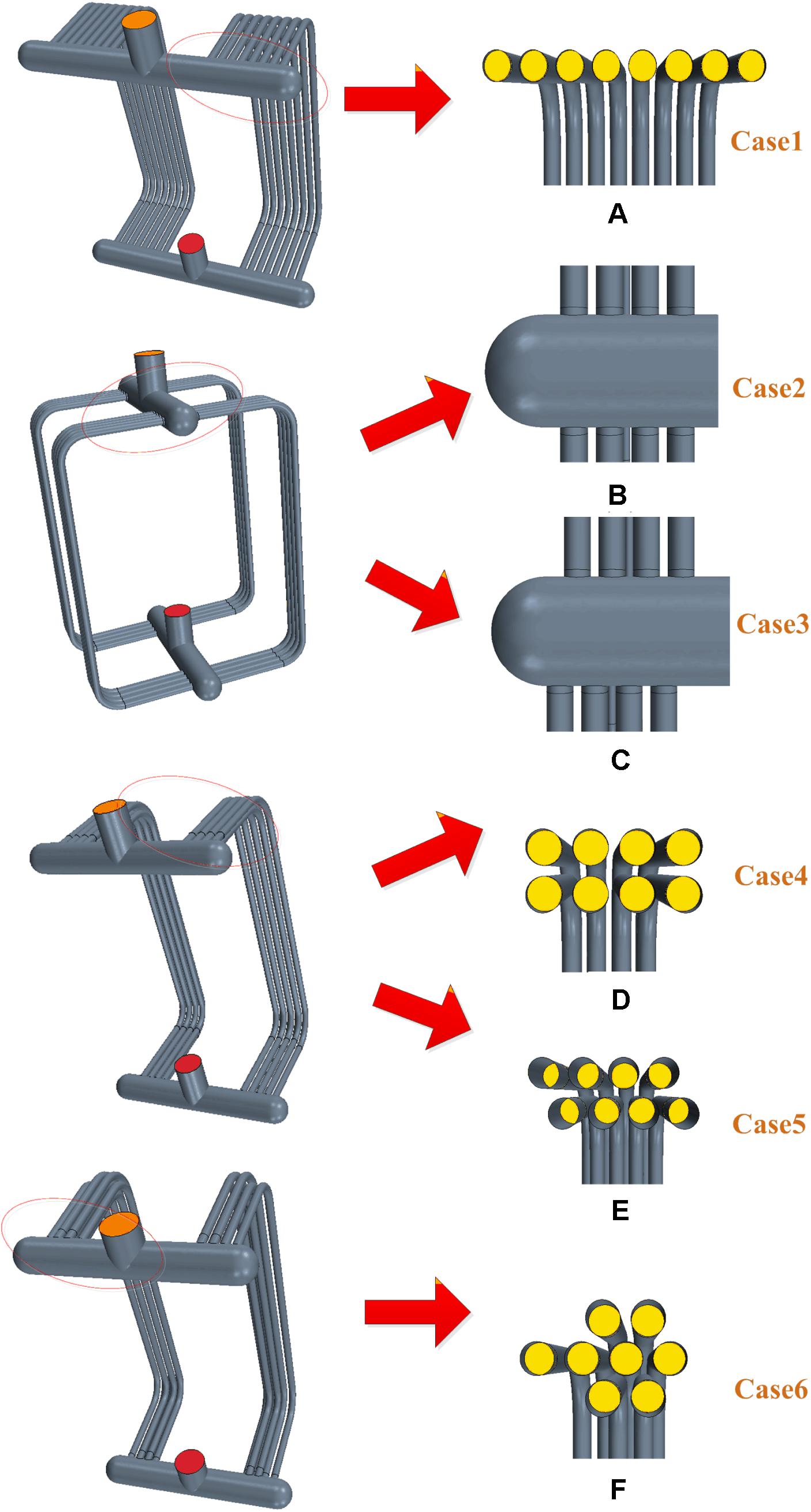
Figure 1. The three dimensional geometry of six different tube arrangements for the central-type heat exchanger. (A–F) Stands for the number of six different structures.
For the heat exchanger, the dividing and combining header diameter is 180 mm, the tube diameter is 44 mm, and the height of the heat exchanger is 1.7 m, the tube distance is 0.044 m, the tube length is 1.9 m, and the angles between the tube and the headers is 90 degree.
Solving Process and Boundry Conditions
The heat exchanger three dimensional model is created by the CAD module in the Star-ccm+. And the grid processing is accomplished by the Star-ccm+.
For the boundary conditions, velocity-inlet is selected for the inlet, the pressure outlet selected for the outlet is set to zero gauge pressure, and the walls are set to no slip condition and rough. The k–ε turbulent model is chosen as the turbulence model. When all of the residuals are less than 1 × 10⁻⁴, solutions are considered to be completely convergent.
For the evaluation of the flow distribution, two dimensionless parameters Φ and β have been utilized.
Where the mi and mav represent the mass flow rate through the ith tube and the average mass flow rate, respectively. And the M represents the total flow rate. And the Φ means the flow maldistribution coefficient, the smaller the Φ is, the better the flow distribution is. The βi stands for the ratio of the flow rate through ith tube to the total flow rates.
Governing Equations and Model Validation
The governing equations are listed below.
The steady-state continuity equation is expressed as
The steady-state momentum conservation equation is expressed as
The steady-state transport equation for k is expressed as
The steady-state transport equation for ε is expressed as
Where
K stands for turbulent kinetic energy;
ε stands for turbulent energy dissipation rate;
ρ stands for density of the working fluid;
u stands for velocity;
μt stands for turbulent dynamic viscosity.
In this present work, no phase change happens. For the single-phase flow, the flow distribution in the heat exchanger is determined by the geometry of the heat exchanger and has little relationship with the heat transfer. Therefore, the heat transfer process is beyond the consideration.
For the grid independence test and the model validation, we have done detailed work in our previous study (Zhou et al., 2017). And they will not be illustrated here.
Results and Discussion
The Flow Distribution and the Pressure Loss for Different Tube Arrangement
For six different kinds of tube arrangement, the flow maldistribution coefficient and the pressure loss are shown in Figure 2. It shows that the case1 shows the best flow distribution and the least pressure loss, however, it cost the most space occupation and material. For the case2 and case3, both the flow maldistribution coefficient and the pressure loss are very close to each other. It shows that if tubes are arranged in single row at two opposite sides of the heat exchanger, there is no obvious different effect on the flow distribution uniformity and pressure loss for the aligned arrangement and staggered arrangement. However, for the double row arrangement on one side of the heat exchanger, the staggered arrangement shows better in both of the flow distribution uniformity and the pressure loss than aligned arrangement. And, comparing to the case1, the double-row arrangement brings more flow maldistribution and pressure loss. For the case6, three-row arrangement reduces the flow maldistribution and the pressure loss comparing to the double-row arrangement. In the following part, the pressure distribution in the header will be analyzed to figure out the reason behind results of different tube arrangements.
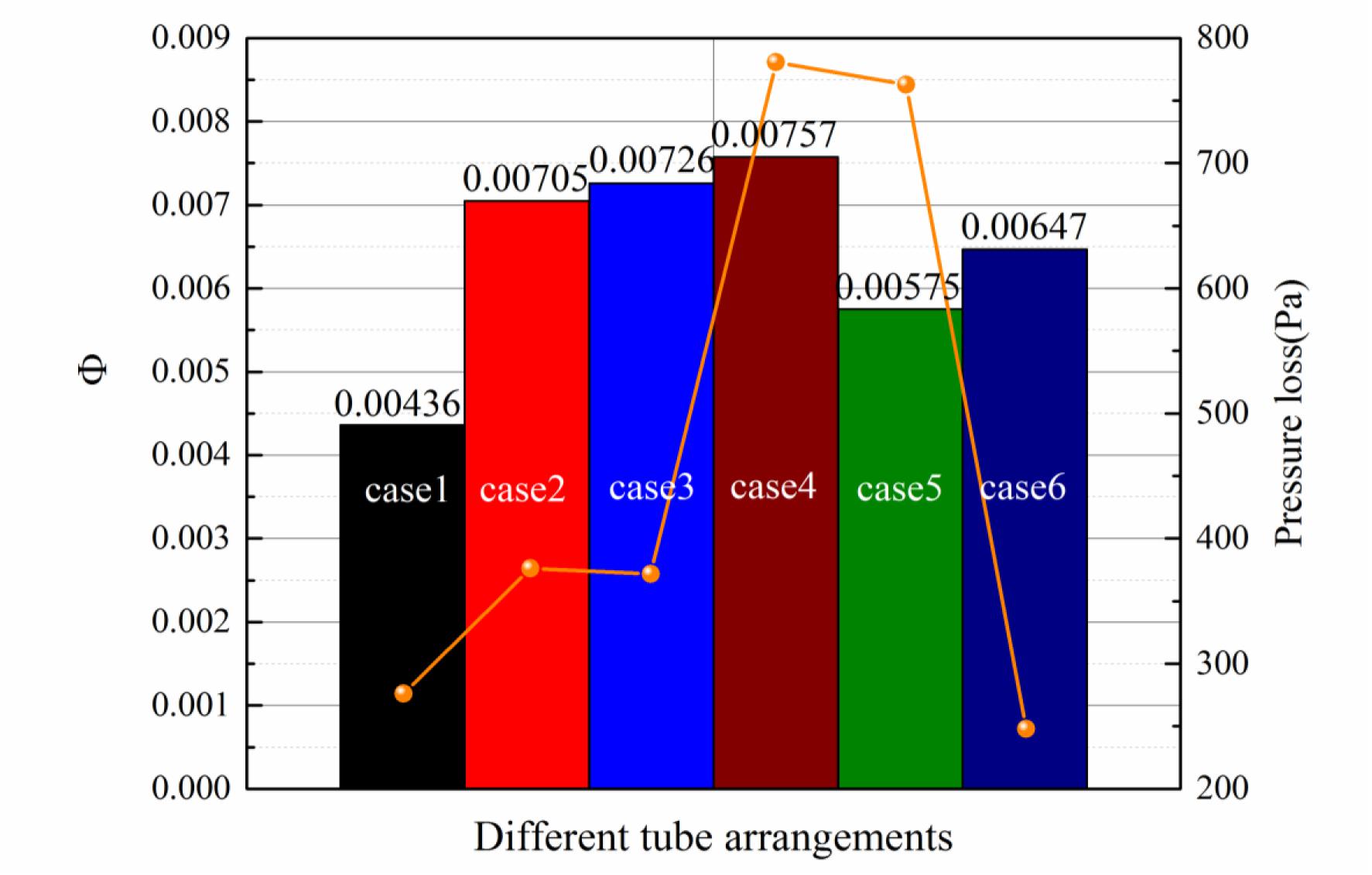
Figure 2. The flow distribution cofficient and the pressure loss for different tube arrangements.
The Flow Distribution and the Pressure Distribution for Single-Row Arrangement
For the tube arrangement of the case1, case2, and case3. They all belong to the single-row arrangement. Therefore, the flow distribution and the pressure distribution of case1, case2, and case3 will be analyzed together in this part. The Figure 3A, shows the flow distribution for the case1, case2, and case3. Firstly it can be seen that the flow distribution for the case2 and case3 are almost the same. And it means that with the single-row arrangement on both sides of the central-type heat exchanger, the staggered arrangement shows little difference from the aligned arrangement. Also, the flow distribution for the case1 shows a lot of difference from that for the case2 and case3. It is because of the difference in the pressure distribution inside the header. The Figure 3B shows the pressure distribution in the dividing header for the case1, case2, and case3. In the header, the pressure distribution is mainly controlled by pressure recovery effect and the frictional resistance (Acrivos et al., 1959). The pressure recovery effect increases the pressure and the frictional resistance reduces the pressure. For the compact heat exchanger, the pressure recovery effect is higher than the pressure decrease caused by the frictional resistance, therefore, the pressure will increase along the direction of the main stream as seen in Figure 3B for case1. However, for the case2 and case3, the pressure along the main flow direction decrease. Differently from the case1, the main stream is divided into two sides rather than one side as in the case1. And it will bring more local pressure loss, therefore, the pressure decreases along the main stream. This pressure distribution is different from the classic pressure distribution theory for the compact heat exchanger with the tube arrangement at one side. And it shows that the discipline of the pressure distribution for compact heat exchanger will change with different tube arrangement.
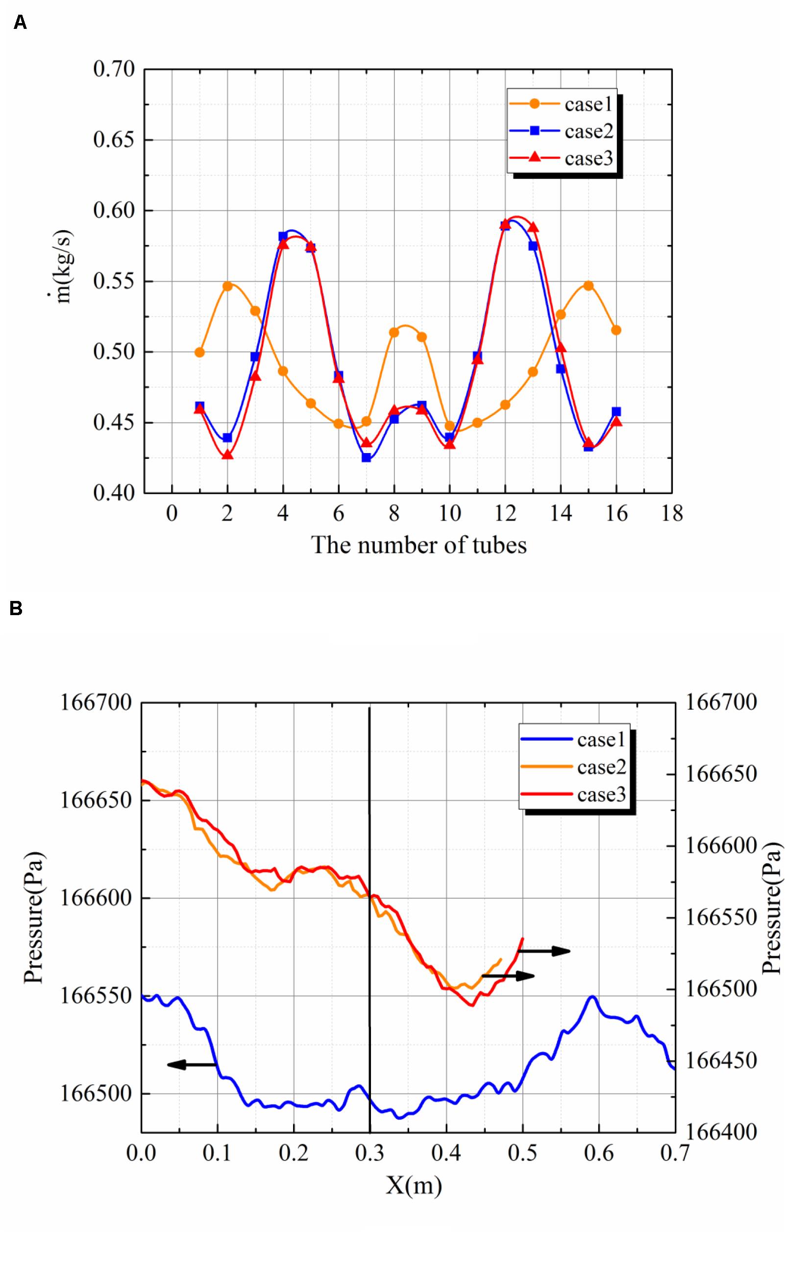
Figure 3. (A) The flow distribution in tubes for case1, case2, and case3. (B) The pressure distribution in the dividing headers for case1, case2, and case3.
The Flow Distribution and the Pressure Distribution for Double-Row Arrangement
The Figure 4A shows the flow distribution for the case1, case4 and case5. For these three cases, tubes are all arranged at one side of the heat exchanger. For the case4 and case5, there are two rows of the tube, the length of the inner-row tube is less than that of the outer-row tube. And it is can be seen that the flow distribution in inner tubes are worse than that in outer tubes. Besides, the difference between the maximum flow and the minimum flow in outer tubes is larger than that in inner tubes. It is because that inlets of outer tubes is lower than inlets of inner tubes, therefore, the pressure at the inlet of outer tubes will be higher than inlets of inner tubes. And higher pressure means larger fluctuation in pressure distribution and worse flow distribution.
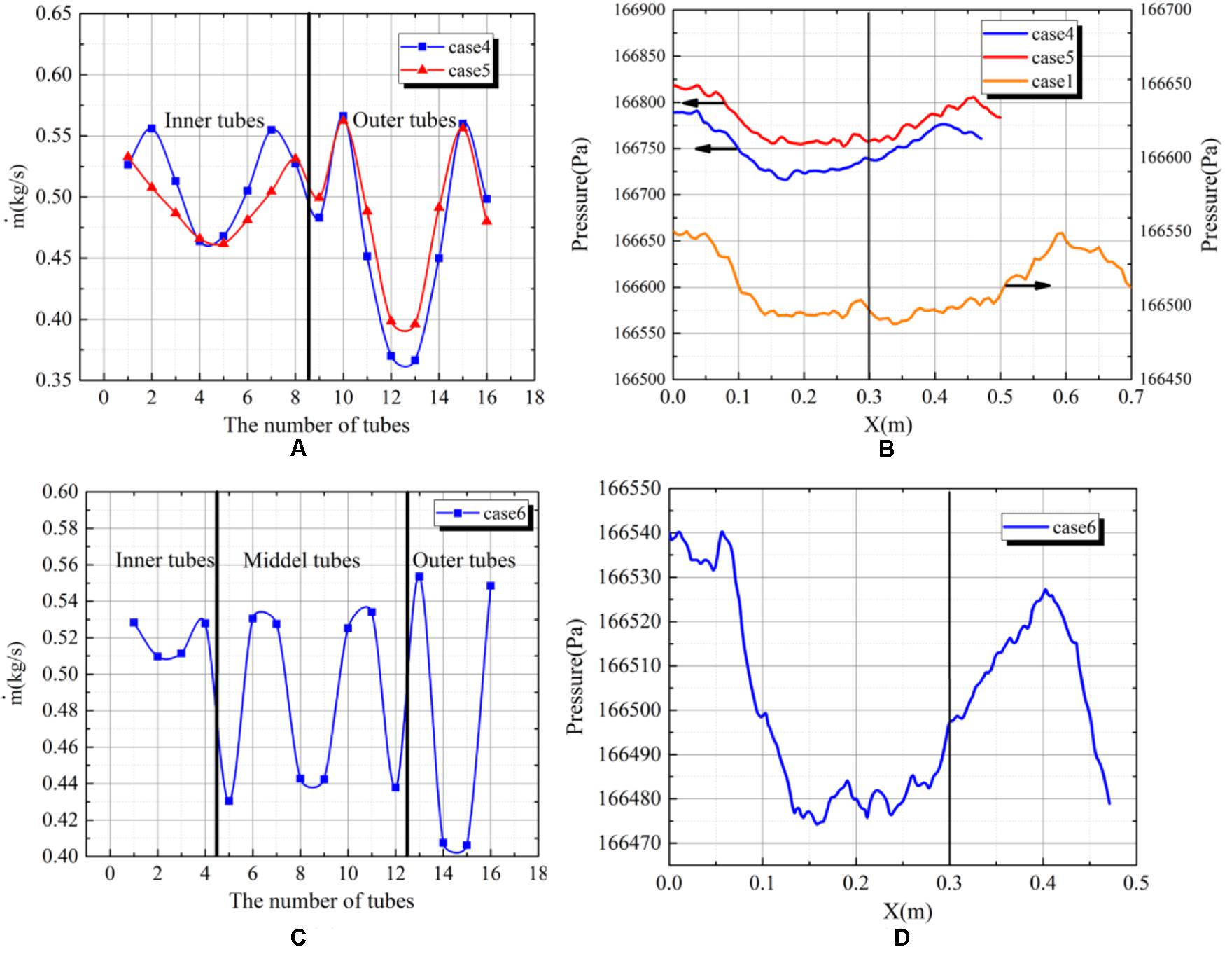
Figure 4. (A) The flow distribution in tubes for case4 and case5. (B) The pressure distribution in the dividing headers for case1, case4 and case5. (C) The flow distribution in tubes for case6. (D) The pressure distribution in the dividing headers for case6.
Comparing to the case1, the increase amplitude in pressure is bigger for the case4 and case5. And the difference in pressure distribution in the dividing header is mainly caused by the tube arrangement. Comparing to the case1, at each position of the tube, there are two tubes instead of one. And it means that the pressure recovery effect is bigger for the case4. For the case5, the staggered arrangement leads to a the smaller tube pitch than that for the case1. It means that along the direction of the main stream, the pressure will increase more quickly over unit distance. And it can be seen that in the Figure 4B, that the pressure is rising faster for the case4 and case5 than that for the case1. However, a quicker increase in the pressure contributes to a less uniform pressure distribution, then leads to a worse flow distribution.
The Flow Distribution and the Pressure Distribution for Three-Row Arrangement
The Figure 4C shows the flow distribution for the case6. There are three rows of tubes, namely inner tubes, middle tubes and outer tubes. It can be seen that the flow distribution in outer tubes are more uniform than that in inner and middle tubes. It is similar to that for the case4 and case5. The positions of inlets of outer tubes are lower than that of inner tubes, therefore, the pressure fluctuation will be larger and contribute to a worse flow distribution. The Figure 4D shows the pressure distribution along the central line of the dividing header. Due to the more densely tube arrangement, the pressure along the direction of the main stream rise more quickly. And most water flows into front tubes, therefore, at the area of behind tubes, the pressure recovery effect is small leading to a quick going down in pressure.
The Pressure Loss for Different Tube Arrangements
Comparing to the case1, the case2 and case3 brings more pressure loss. It is because that the diversion of fluid to both sides bring more local pressure loss. For the case4 and case5. The more densely tube arrangement contributes to a more local pressure loss at the inlet of tubes. Comparing to the case4, the staggered arrangement for the case5 brings less local pressure loss than the aligned arrangement. For the case6, the more densely tube arrangement comparing to the case4 and case5, making a shorter length of the dividing header and the combining header. And the frictional pressure loss is decreased, therefore, the pressure loss for the case6 is less than that in case4 and case5.
Conclusion
This study investigated the effects of six different tube arrangements on the flow distribution characteristics and pressure loss in the central-type heat exchanger. The conclusions are as follows:
1. Under the premise of fixed important geometrical dimensions such as header diameter, tube diameter, inlet and outlet diameter, etc., the tube arrangement has a significant effect on the flow distribution characteristics and resistance characteristics of the heat exchanger tubes.
2. Due to the larger header length for the case1, more frictional pressure drop is introduced to make the static pressure distribution in the header more uniform, and the flow distribution uniformity is the best among all cases.
3. For the single row arrangement on both sides of the heat exchanger, the pressure distribution is different from the classic pressure distribution theory for the compact heat exchanger with the tube arrangement at one side. The increase in pressure caused by the pressure recovery effect is less than the decrease in pressure caused by the local pressure loss. Therefore, the pressure decreases along the direction of the main stream rather than increase as in the classic pressure distribution theory for the compact heat exchanger with the tube arrangement at one side. And it shows that the discipline of the pressure distribution for compact heat exchanger will change with different tube arrangements.
4. For the case2 and the case3, the aligned and staggered tube arrangements show no apparent difference in flow distribution and the pressure loss of the heat exchanger.
5. For the double-row tube arrangement on one side of the heat exchanger such as case4 and case5, the staggered tube arrangement contributes to a more uniform flow distribution and the flow distribution coefficient has been decreased by 24%, comparing to the aligned tube arrangement.
6. For the double-row and three-row tube arrangement, the flow distribution is worse in outer tubes. Besides, the difference between the maximum flow and the minimum flow in outer tubes is larger than that in inner tubes.
Nomenclature (Zhou et al., 2017).
Φ Evaluation parameter of flow maldistribution
k turbulent kinetic energy
ε turbulent energy dissipation rate
ρ density of the working fluid
u velocity
σk, σε turbulent constants
μt turbulent dynamic viscosity
Data Availability Statement
The datasets generated for this study are available on request to the corresponding authors.
Author Contributions
JZ finish this manuscript. ZM give some useful advice. ZS provide the guideline for the manuscript. All authors contributed to the article and approved the submitted version.
Conflict of Interest
YY was employed by company Research and development Center, China Nuclear Power Engineering.
The remaining authors declare that the research was conducted in the absence of any commercial or financial relationships that could be construed as a potential conflict of interest.
References
Acrivos, A., Babcock, B. D., and Pigford, R. L. (1959). Flow distributions in manifolds. Chem. Eng. Sci. 10, 112–124. doi: 10.1016/0009-2509(59)80030-0
Liu, H., and Li, P. (2013). Even distribution/dividing of single-phase fluids by symmetric bifurcation of flow channels. Int. J. Heat Fluid Flow 40, 165–179. doi: 10.1016/j.ijheatfluidflow.2013.01.011
Liu, H., Li, P., Jon, V. L., and Daniel, J. R. (2012). Experimental study of the flow distribution uniformity in flow distributors having novel flow channel bifurcation structures. Exp. Therm. Fluid Sci. 37, 142–153. doi: 10.1016/j.expthermflusci.2011.10.015
Liu, H., Li, P., and Lew, J. V. (2010). CFD study on flow distribution uniformity in fuel distributors having multiple structural bifurcations of flow channels. Int. J. Hydrogen Energy 35, 9186–9198. doi: 10.1016/j.ijhydene.2010.06.043
Said, S. A. M., Rached, B. M., Habib, M. A., and Siddiqui, M. U. (2014). Reducing the flow mal-distribution in a heat exchanger. Comput. Fluids 107, 1–10. doi: 10.1016/j.compfluid.2014.09.012
Shi, J. Y., Xiao, H. Q., Zhao, G. Q., and Chen, J. P. (2010). Effect of inlet manifold structure on the performance of the heater core in the automobile air-conditioning systems. Appl. Therm. Eng. 30, 1016–1021. doi: 10.1016/j.applthermaleng.2010.01.016
Wang, C. C., Yang, K. S., Tsai, J. S., and Ing, Y. C. (2011). Characteristics of flow distribution in compact parallel flow heat exchangers, part II: modified inlet header. Appl. Therm. Eng. 31, 3235–3242. doi: 10.1016/j.applthermaleng.2011.06.003
Wang, J., and Wang, H. (2015). Discrete method for design of flow distribution in manifolds. Appl. Therm. Eng. 89, 927–945. doi: 10.1016/j.applthermaleng.2015.06.069
Wei, M., Boutin, G., Fan, Y., and Luo, L. (2016). Numerical and experimental investigation on the realization of target flow distribution among parallel mini-channels. Chem. Eng. Res. Des. 113, 74–84. doi: 10.1016/j.cherd.2016.06.026
Wei, M., Fan, Y., Luo, L., and Gilles, F. (2015a). CFD-based evolutionary algorithm for the realization of target fluid flow distribution among parallel channels. Chem. Eng. Res. Design 100, 341–352. doi: 10.1016/j.cherd.2015.05.031
Wei, M., Fan, Y., Luo, L., and Gilles, F. (2015b). Fluid flow distribution optimization for minimizing the peak temperature of a tubular solar receiver. Energy 91, 663–677. doi: 10.1016/j.energy.2015.08.072
Ye, W. B. (2017). Design method and modeling verification for the uniform air flow distribution in the duct ventilation. Appl. Therm. Eng. 110, 573–583. doi: 10.1016/j.applthermaleng.2016.08.177
Yuan, P., Jiang, G. B., He, Y. L., Yi, X. L., and Tao, W. Q. (2013). Experimental study on the performance of a novel structure for two-phase flow distribution in parallel vertical channels. Int. J. Mult. Flow 53, 65–74. doi: 10.1016/j.ijmultiphaseflow.2012.05.006
Zhou, J., Ding, M., Bian, H., Zhang, Y., and Sun, Z. (2018). CFD simulation for the effect of the header match on the flow distribution in a central-type parallel heat exchanger. Chem. Eng. Res. Des. 136, 144–153. doi: 10.1016/j.cherd.2018.04.047
Zhou, J., Ding, M., Bian, H., Zhang, Y., and Sun, Z. (2019). Characteristics of flow distribution in central-type compact parallel flow heat exchangers with modified inlet and header. Appl. Therm. Eng. 166:114636. doi: 10.1016/j.applthermaleng.2019.114636
Keywords: flow distribution, tube arrangement, central-type, compact, pressure loss
Citation: Zhou J, Yue Y, Meng Z and Sun Z (2020) Numerical Study of the Influence of Tube Arrangement on the Flow Distribution Inside the Heat Exchanger in the PCCS. Front. Energy Res. 8:164. doi: 10.3389/fenrg.2020.00164
Received: 14 October 2019; Accepted: 29 June 2020;
Published: 21 July 2020.
Edited by:
Muhammad Zubair, University of Sharjah, United Arab EmiratesReviewed by:
Yen-Shu Chen, Institute of Nuclear Energy Research (INER), TaiwanLuteng Zhang, Chongqing University, China
Arash Mirabdolah Lavasani, Islamic Azad University Central Tehran Branch, Iran
Xiaowei Li, Tsinghua University, China
Copyright © 2020 Zhou, Yue, Meng and Sun. This is an open-access article distributed under the terms of the Creative Commons Attribution License (CC BY). The use, distribution or reproduction in other forums is permitted, provided the original author(s) and the copyright owner(s) are credited and that the original publication in this journal is cited, in accordance with accepted academic practice. No use, distribution or reproduction is permitted which does not comply with these terms.
*Correspondence: Jian Zhou, emhvdWppYW5AaHJiZXUuZWR1LmNu; MTgwNDU2MjU3MjlAMTYzLmNvbQ==; Zhaoming Meng, bWVuZ3poYW9taW5nQGhyYmV1LmVkdS5jbg==; MTAyMzI0MDU4NUBxcS5jb20=