 Soumya Ranjan Das
 Prakash K. Ray2
 Arun Kumar Sahoo
 Karthik Balasubramanian
95% of researchers rate our articles as excellent or good
Learn more about the work of our research integrity team to safeguard the quality of each article we publish.
Find out more
ORIGINAL RESEARCH article
Front. Energy Res. , 28 February 2020
Sec. Process and Energy Systems Engineering
Volume 8 - 2020 | https://doi.org/10.3389/fenrg.2020.00023
This article is part of the Research Topic Multilevel Converters: Control Techniques for Renewable Energy Resources View all 8 articles
The existence of harmonics in the power distribution system (PDS) is treated as the most serious issue that affects its stability and reliability. The active power filter (APF) therefore plays a vital role in PDS to compensate for the harmonics for the improvement of the power quality (PQ) and to keep the total harmonic distortion (THD) below 5% as per IEEE-519. In this work, a three-phase four-wire (3P-4W) multi-level inverter (MLI)-based APF is proposed to overcome the shoot-through effect (STE) and reduce the distortions in the supply current. The control of the voltage source inverter (VSI) is achieved using an Adaline-based LMS (A-LMS) algorithm with a hysteresis current controller. The proposed filter that uses the A-LMS technique is compared with the conventional recursive least square (RLS) algorithm. The A-LMS approach is mainly operated for maintaining the dc link voltage of MLI, which follows the principle of capacitor energy and reduces the total harmonic distortion (THD) under different load variations. The performance of MLI under different load conditions is designed, developed, and validated by using a MATLAB/Simulink environment, and the preeminent features are established.
In the era of modern power systems, it is quite a promising task to reduce the harmonics in the PDS. The harmonics are generally caused due to the usage of a non-linear load. Therefore, amongst the probable solutions in recent years, it is observed that multi-level inverter (MLI)- (Siddique et al., 2019a,b) based APF has the capability to control and regulate the electrical disturbances and improvise the PQ by injecting the compensating current (Babu et al., 2015) to the PDS. MLIs are widely used in various areas like HVDC systems (Xu et al., 2014), battery energy storage systems (Soong and Lehn, 2014), as well as wind (Gangui et al., 2012) and solar energy systems (Yousri et al., 2019). Significant developments linked with the circuit topology (Siddique et al., 2019c) and control techniques of the MLI have been noticed in recent days. Recent studies have demonstrated the importance of the MLI, which delivers an ideal functionality for high and medium voltage systems (Ali and Krishnaswamy, 2018). With the use of an MLI, the compensations in current harmonics are very effective in improving the PQ. An MLI can provide improved PQ by operating the power semiconductor devices at a frequency near to the fundamental (Rodriguez et al., 2002). Of course, for low-power applications, the switching frequencies of the switching devices are not restricted, but, at its lower value, the efficiency of the converter increases (Ozdemir et al., 2008). An MLI also offers advantages, such as the possibility of direct interfacing to the medium voltage system without using a coupling transformer, the production of output voltages with lower distortions, having high power conversion characteristics, and providing a high equivalent switching frequency effect at rather lower values.
Different configurations of MLIs have been discussed so far in this area. In Rodriguez et al. (2009) and Pratheesh et al. (2017), the neutral clamped MLI is discussed where the authors presented the modulation and control techniques with special attention to the distribution losses. In Zhang et al. (2013) and Lei et al. (2017), the authors have discussed the function of the flying capacitors for harmonics and unbalanced current compensation. In Karasani et al. (2016), and Gupta et al. (2015), the performance of the cascaded MLI (CMLI) has been analyzed. Among the available MLI topologies, the CMLI is extensively used; it provides a modular design and can be directly linked to the grid at PCC instead of using a transformer (Ertl et al., 2002). Moreover, it provides power semiconductors with a lower rating compared to the standard two-level configurations, thereby improving the reliability under faulty situations. The MLI is given higher preference over other switching topologies because the MLI achieves the output of equal voltage by using fewer switching devices.
In this paper, a 3P-4W H-bridge interleaved buck-type active power filter (HILBAPF) (Panda and Patel, 2014) is implemented. HILBAPF has been developed to overcome the problems incurred by the conventional MLI in balancing the capacitor voltages and to exclude the interfacing transformer. Also, the conventional MLIs are not capable of managing faults and fault ride-throughs. Another major factor of the MLI is reliability, which decreases by means of STE. The supply voltages, with an unbalanced and non-sinusoidal supply, combined with the existence of negative and zero sequence components in the supply source, results in huge losses and excessive temperature increases in the PDS. Therefore, compensating for the zero sequence components in the neutral wire has become a primary task in the improvement of the PQ. A comparative analysis between conventional inverter and proposed MLI is provided in Table 1.
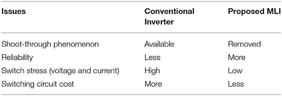
Table 1. Comparative analysis between Conventional Inverter and proposed MLI.
Various control techniques have been used so far in this area to accomplish the compensation task, which comprises the instantaneous power theory (p-q) (Hachani et al., 2017), the synchronous reference frame (SRF) theory (Hoon et al., 2016), the discrete Fourier transform approach (Wang et al., 2016), and the deadbeat controller (Qi et al., 2017). However, adaptive filters (Chilipi et al., 2016) play an important role in compensating for the harmonics by injecting the required current to the power grid. Traditionally, a recursive least square (RLS) (Das et al., 2017) is employed, which offers improved performance, simplicity, robustness, and a lower computational burden. However, they are still altered due to factors like a slow convergence rate, longer iteration rate, and large storage capacity. These issues thus sort out use the Adaline approach (Subudhi et al., 2012). The Adaline approach is the most commonly used artificial neural network (ANN) technique to extract the fundamental and/or harmonic components. ANN has been projected as an attractive estimation and regression technique due to its parallel computing nature and high learning capability.
Moreover, the A-LMS is very simple and produces fewer computational problems. It offers natural linearity and the methodology is fast. In this study, therefore, an A-LMS (Merabet et al., 2017) approach in the MLI for calculating the reference current extractions is presented. The proposed approach provides improved robustness, speed, and efficiency along with a lower switching frequency or lower current ripple as compared to standard two-level topologies. Moreover, it produces a sinusoidal component from a non-linear supply voltage. The performance is realized using a Matlab/Simulink and compared with the conventional RLS to check the effectiveness of the proposed system.
The main idea in this work is to design a power system model with an MLI for compensating for the current harmonics and reactive power compensation by supplying a compensating current and reducing the THD percentage below 5% as per IEEE standard. The proposed system is tested under balanced and unbalanced load cases. The reference source current extraction is realized using an A-LMS. The A-LMS extracts the current in a simpler way with a shorter period of execution. The A-LMS algorithm is very dynamic for severe load variations. The proposed method improves the effective dynamic performance of the MLI for compensating for load currents with a reduced computational burden. The proposed technique is easily realized on digital processors and performs the fewest number of calculations.
The paper is arranged into several sections. Section System Configuration provides detail explanations of 3-phase, 4-wire HILBAPF, section Control Methodology provides proposed Adaline techniques, section Results and Discussion provides the result analysis for PQ improvement, and section Conclusions provides the conclusion.
To obtain the fundamental supply current, the MLI must inject or absorb a compensating filter current. The compensated current must be the same and be in phase opposition to the harmonic components. The 3P-4W with HILBAPF is shown in Figure 1. The proposed model is designed especially for high voltage, medium-to-high power applications with an objective to end shoot-through problems. It consists of three single-phase H-bridge inverters. The advantage of this topology is that the voltage across in each H-bridge interleaved buck inverter appears at the single phase voltage only, and hence the dc link reference voltage required is decreased by times as compared to the other conventional MLI. The proposed topology requires only one dc link capacitor voltage out of the three individual phases for reference current generation, and this consequently reduces the voltage regulation complexness.
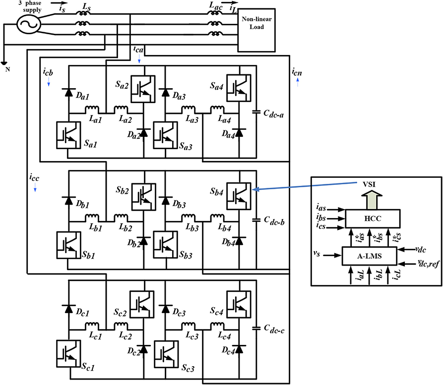
Figure 1. Proposed system configuration.
For the 3P-4W HILBAPF, the following mathematical equations are presented:
where, is(a+b+c), iL(a+b+c), and icomp(a+b+c) represent the corresponding source, load, and compensating current of phase a, b, and c, respectively, while, isn, iLn and icompn represent the corresponding neutral supply, load, and compensating currents. Now, in HILBAPF, the compensating current can be presented as the sum of the two coupling inductors current for individual phases:
The dc-side capacitance (Cdc) of HILBAPF is given as:
where, Cdc, Vdc, Vdcmin, I, Vs(t), and Δt are, respectively, the capacitance of the DC-bus, voltage across the DC-side, minimum dc-bus voltage level, phase current, phase voltage, and change of time where the DC-bus voltage is to be improved. The control strategies of VSI using A-LMS are discussed in subsequent sub-sections.
To obtain the fundamental supply current, the APF must inject or absorb a compensating filter current. The compensated current must be the same and be in phase opposition to the harmonic components. The 3P-4W MLI is shown in Figure 1. The performance of the 3P-4W MLI depends on the control strategy designed. In this paper for improving the reliability of the proposed system, two different control strategies, the RLS and A-LMS techniques, are used for controlling the VSI of 3P-4W MLI. The details of the controlling techniques are discussed in subsequent sub-sections.
The RLS approach, with its simple structure and robust performance, is extensively implemented in many applications. The RLS technique is very simple; it reduces noise and automatically adjusts parameters. During the steady state, the active power offered by the power system is equal to the active power required by the load, and there is therefore no active current that flows through the MLI. Furthermore, the DC-link voltage is fixed, and its waveform has six ripples. Therefore, if the transient state occurs due to the load variation, the DC-link capacitor will provide the active power variance between the supply system and load, which may in turn produce a fluctuation in the DC link. In order to sustain a fixed DC-bus voltage and weaken the six ripples in the waveform, the MLI employs an RLS filter to get a DC-bus active parameter (Adcx) for each phase.
In this approach for obtaining the compensation current generation, the RLS filter is used in the MLI such that the dc link active current parameter (Adcx) is obtained with a constant dc link voltage and so that it can be ripple free in the waveform. Figure 2 provides the functioning of the RLS algorithm, where Vref references the dc link voltage, and Vdc(i) references the dc link voltage, having an instantaneous sampling value. To sustain the dc link, the instantaneous active power required to maintain the DC-link voltage (Pdc)is specified as
where, C, termed as the DC-bus capacitor, and Adcx can be obtained as
The final Ax, i.e., the active parameter, is obtained as
For each phase, the instantaneous current is given as
where,
In a grid voltage, harmonics do not exist, and therefore instantaneous voltage is expressed as
For each phase, the reference active current is expressed as
The instantaneous reference compensation current is identified as
Therefore, for the distortion limit, the reference compensating current is injected into the power system.
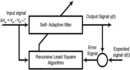
Figure 2. Flow chart of RLS filter.
This algorithm is a combined technique between the Adaline and LMS algorithm. The weights in Adaline are basically updated using the LMS algorithm. Due to its simple structure and robust nature, the A-LMS algorithm is widely implemented in signal processing and control system application. The proposed technique is used to calculate the reference current components for the MLI. The convergence rate of the LMS algorithm depends on the fixed step-size parameter. The A-LMS offers several advantages, such as a simple structure, and it can be realized easily in practical applications. The results of frequency tracking, especially harmonics detection, demonstrate that the A-LMS algorithm can be utilized effectively in analyzing the PQ issues. The learning capacity of the ANN supports online adaptation to any variation in electrical parameters. Each neuron in ANN is treated as an elementary neuron. Each neuron collects a number of input variables from upstream neurons. Each input is assigned with a weight “w” representative of the strength of the connection. The output of the neuron acts on the activation function of the weighted sum inputs. Figure 3 illustrates the configuration of the Adaline neural network.
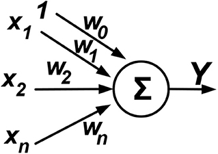
Figure 3. Basic architecture of Adaline neural network.
The Adaline output can be computed as per Equation (12):
where x and w (w0, w1…wn) are the input and weight vector, respectively, with n being the dimension, and Y being the estimated output.
The A-LMS technique is designed for the extraction of the real fundamental frequency component of the load current. For maintaining a fixed DC-bus voltage, a PI controller is employed in which the DC-bus voltage is compared with its reference value.
Considering a three-phase system where the source voltage is sinusoidal and it is expressed as
and the current in the non-linear load is given as
Equation (14) can be represented as
where, , and are the positive sequence active load current, positive sequence reactive load current, and negative sequence load current (harmonic components), respectively.
In a single phase the current active component (ip), is expressed as
The unit vector is denoted as us, and wm is denoted as the calculated weight of the A-LMS.
Therefore, the iterated weight is given as
where μ is termed as the convergence coefficient.
The error across the DC-bus is given as
where the output from PI is expressed as
and where, IP1 = kpdc[Δvdc(n) − Δvdc(n−1)]+kidcΔvdc(n) as well as kpdc and kidc are the proportional and integral gain of the controller, respectively.
The three-phase source reference currents are expressed as
where, , and are considered as reference source currents. These currents are compared with detected source currents, and their resultant output is supplied to the HCC (hysteresis current controller) for gating signal generation. The detailed algorithm is shown in Figure 4. The proposed technique needs less computational workout. Moreover, this technique instantaneously compensates for the source currents, which is not easy in the case of conventional techniques. The weights are computed online using the LMS algorithm. The weights are averaged not for the purpose of averaging at a fundamental frequency but for the canceling of the sinusoidal oscillating components in weights, which are available due to load current harmonics. The weight average in each different phase is depicted in Figure 4.
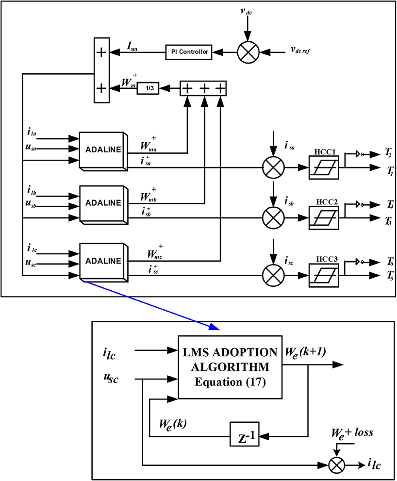
Figure 4. Block diagram of A-LMS algorithm.
The ADALINE receives the PCC voltage and the individual load current, and it generates the individual weight with the reference source current. From the figure, it is clear that, for switching signal generation, the sensed source currents are subtracted from the reference source currents, and then the individual source current errors are supplied to the HCC.
A power system model in the MATLAB/ SIMUINK and Simpower-System Block set is designed to analyze the function of the proposed controller in the three-phase system using the MLI. The complete system is composed mainly of a three-phase source, a non-linear load (balanced and unbalanced load), the MLI system, and the PI controller with different proposed control strategies.
The performance of the proposed power system model is measured with the conventional RLS technique and the proposed Adaline-LMS technique under balanced and unbalanced loads. The concerned parameters of the system are provided in subsequent subsections.
To investigate the performance of the system, the test is carried out using a three-phase supply source and a non-linear load. The non-linear loads for balanced and unbalanced loads are provided in the Appendix section. Due to the presence of harmonics, it is noted that the load current is distorted from the normal sinusoidal current when a non-linear load is connected. The current wave forms of the distorted load currents during an unbalanced non-linear load are illustrated in Figure 5A. From the figure, it can be seen that the distortion with a current dip is found from 0 to 0.05 s. After 0.05 s, the distorted load current is maintained at a rated value up to 0.2 s. The THD value found during the unbalanced load is around 38.97%, which is illustrated in Figure 5B. Now, the proposed model is operated during the balanced load. The distortion in the load current is found around 28.53%, which is found to be less compared to the case of unbalance load. The waveforms of the load current distortions are illustrated in Figures 5C,D. It is observed that in both of the cases the distortion of harmonics is not maintained as per the IEEE-519 standard. Therefore, to reduce the harmonics and to improve the PQ, the power system is run under the MLI using the RLS and A-LMS harmonics estimation technique. The individual test for both the RLS and A-LMS are analyzed under different load conditions. The performances of both techniques are observed individually to show the feasibility of the control technique.
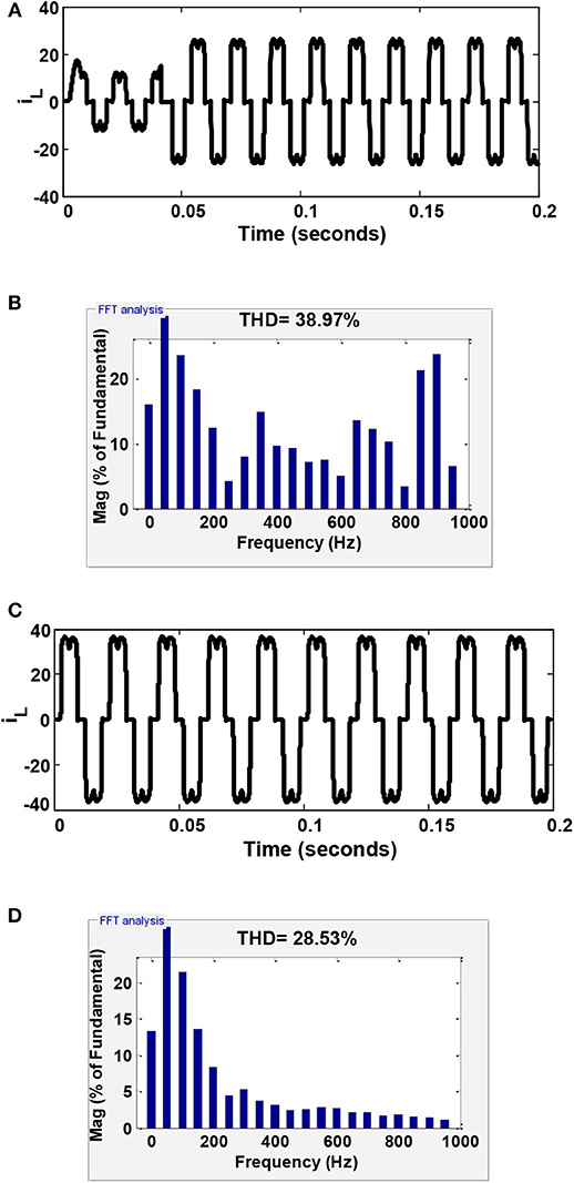
Figure 5. Performance of the load current without using the MLI: (A) during an unbalance load; (B) THD value under an unbalance load; (C) during a balanced load; and (D) THD value under a balance load.
The performance study of the proposed power system model using the MLI is operated under a balanced load using the RLS and A-LMS techniques. Initially, it was observed that, with the use of the RLS technique, the distortion of voltage harmonics was improved as compared to the case that did not use the compensating device. The case study is designed for the case of balanced load conditions. Figure 6 provides the simulation outcomes of three-phase system using the RLS algorithm. Figure 6A provides the simulation outcomes of single-phase source current, load current, filter voltage, and dc-link voltage. The THD analysis is shown in Figure 6B, and was found to be 1.75%. From the simulation results, it was proven that the load current, which is composed of harmonics, is compensated for by the MLI, and the compensated RLS technique was found to maintain the IEEE-519 standard.
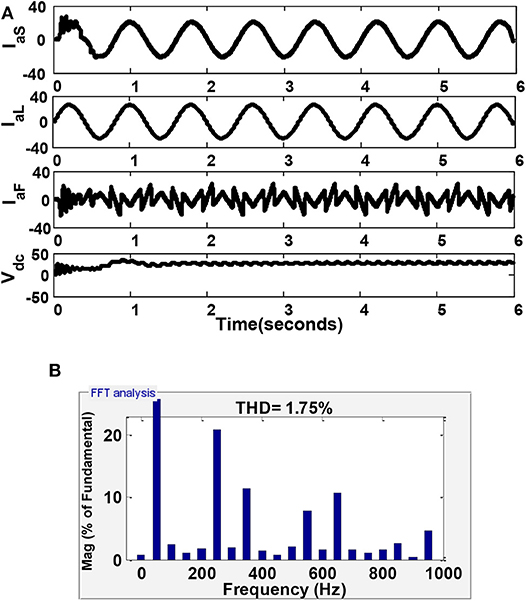
Figure 6. Power quality analysis in the three-phase system using the RLS algorithm under balanced load conditions: (A) simulation results showing supply current, load current, filter voltage, and DC-bus voltage; and (B) THD value of 1.78%.
Furthermore, the proposed model was operated using the A-LMS technique and the corresponding results are depicted in Figure 7. The source and load current, filter voltage, and dc-link voltage are provided in Figure 7A. The THD results are shown in Figure 7B and found to be 1.21%. It is observed that, when using the A-LMS technique under balanced load conditions, the distortions in the harmonics was improved compare to the RLS technique.
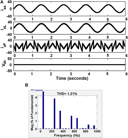
Figure 7. Power quality analysis in three-phase system using the A-LMS algorithm under balanced load conditions: (A) simulation results showing supply current, load current, filter voltage, and DC-bus voltage; and (B) THD value of 1.21%.
In this sub-section, the MLI under the unbalanced non-linear loading condition is observed. In the first case, the system is run using the RLS technique. The corresponding results are shown in Figure 8. The source and load current, filter voltage, and DC-link voltage are produced in Figure 8A. The THD value was found to be 4.20% and is produced in Figure 8B.
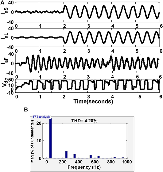
Figure 8. Power quality analysis in three phase system using the RLS algorithm under unbalanced load conditions: (A) simulation results showing supply current, load current, filter voltage, and DC-bus voltage; and (B) THD value of 4.26%.
Furthermore, the test was carried out using the A-LMS technique. The simulation outcomes of the source and load current, the filter voltage, and the DC-link voltage for the single phase is shown in Figure 9A. The corresponding THD results were found to be 3.70%. The THD analysis is shown in Figure 9B.
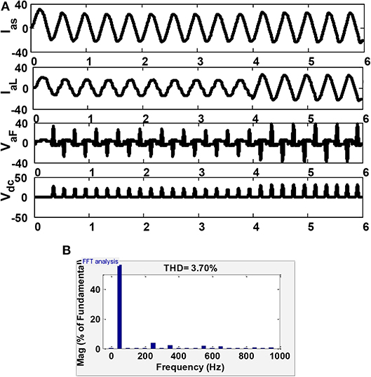
Figure 9. Power quality analysis in three phase system using the A-LMS algorithm under unbalanced load conditions: (A) simulation results showing supply current, load current, filter voltage, and DC-bus voltage; and (B) THD value of 3.72%.
The simulation outcomes revealed that the distortion in the harmonics with the non-linear loads were compensated for using the MLI with the proposed A-LMS technique. It was noticed that the proposed model using the A-LMS provided satisfactory results. The THD of the load voltage was implied to display the better operation of the MLI under such conditions. The comparative analysis of THD is shown in Table 2.
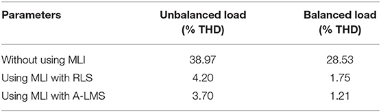
Table 2. Comparative THD analysis of proposed technique under different load conditions.
The proposed power system model employed a 3P-4W MLI. The proposed MLI used the A-LMS technique for reference current generation and was compared with the conventional RLS technique. The performance of the proposed MLI was tested the using Matlab/ Simulink tool. The MLI was operated under balanced and unbalanced loads using both the RLS and A-LMS techniques. Even though both of the techniques were capable of compensate for the harmonics, it was concluded from simulation outcomes that the A-LMS techniques gave better results compared to the conventional RLS technique. The fall in %THD was found to be more satisfactory in the A-LMS technique, which proves the effectiveness of the proposed technique. It was concluded that the compensation in the load current using the A-LMS technique was found to satisfactory compared to the RLS technique. Moreover, the proposed MLI needed only one DC-link voltage to operate, and it was thus simple to control.
The raw data supporting the conclusions of this article will be made available by the authors, without undue reservation, to any qualified researcher.
All authors listed have made a substantial, direct and intellectual contribution to the work, and approved it for publication.
KB was employed by the company Offshore Technology Development Private Ltd.
The remaining authors declare that the research was conducted in the absence of any commercial or financial relationships that could be construed as a potential conflict of interest.
Ali, J. S. M., and Krishnaswamy, V. (2018). An assessment of recent multilevel inverter topologies with reduced power electronics components for renewable applications. Renew. Sustain. Energy Rev. 82, 3379–3399. doi: 10.1016/j.rser.2017.10.052
Babu, T. S., Priya, K., Maheswaran, D., Sathish Kumara, K., and Rajasekar, N. (2015). Selective voltage harmonic elimination in PWM inverter using bacterial foraging algorithm. Swarm Evol. Comput. 20, 74–81. doi: 10.1016/j.swevo.2014.11.002
Chilipi, R., Al Sayari, N., Al Hosani, K., and Beig, A. R. (2016). Control scheme for grid-tied distributed generation inverter under unbalanced and distorted utility conditions with power quality ancillary services. IET Renew. Power Gen. 10, 140–149. doi: 10.1049/iet-rpg.2015.0095
Das, S. R., Ray, P. K., and Mohanty, A. (2017). Improvement in power quality using hybrid power filters based on RLS algorithm. Energy Proc. 138, 723–728. doi: 10.1016/j.egypro.2017.10.207
Ertl, H., Kolar, J. W., and Zach, F. C. (2002). A novel multicell DC-AC converter for applications in renewable energy systems. IEEE Trans. Ind. Electron. 49, 1048–1057. doi: 10.1109/TIE.2002.803212
Gangui, Y., Jigang, L., Gang, M. U., Yu, L., Yang, L., and Wei, S. (2012). Research on modular multilevel converter suitable for direct-drive wind power system. Energy Proc. 17, 1497–1506. doi: 10.1016/j.egypro.2012.02.272
Gupta, K. K., Ranjan, A., Bhatnagar, P., Sahu, L. K., and Jain, S. (2015). Multilevel inverter topologies with reduced device count: a review. IEEE Trans. Power Electron. 31, 135–151. doi: 10.1109/TPEL.2015.2405012
Hachani, K., Mahi, D., and Kouzou, A. (2017). Shunt active power filtering based on the pq theory control. Electrotehn. Electron. Automat. 65, 85–89.
Hoon, Y., Radzi, M. A. M., Hassan, M. K., and Wahab, N. I. A. (2016). A simplified synchronous reference frame for indirect current controlled three-level inverter-based shunt active power filters. J. Power Electron. 16, 1964–1980. doi: 10.6113/JPE.2016.16.5.1964
Karasani, R. R., Borghate, V. B., Meshram, P. M., Suryawanshi, H. M., and Sabyasachi, S. (2016). A three-phase hybrid cascaded modular multilevel inverter for renewable energy environment. IEEE Trans. Power Electron. 32, 1070–1087. doi: 10.1109/TPEL.2016.2542519
Lei, Y., Barth, C., Qin, S., Liu, W. C., Moon, I., Stillwell, A., et al. (2017). A 2-kW single-phase seven-level flying capacitor multilevel inverter with an active energy buffer. IEEE Trans. Power Electron. 32, 8570–8581. doi: 10.1109/TPEL.2017.2650140
Merabet, L., Saad, S., Abdeslam, D. O., and Merckle, J. (2017). Direct neural method for harmonic currents estimation using adaptive linear element. Electr. Power Syst. Res. 152, 61–70. doi: 10.1016/j.epsr.2017.06.018
Ozdemir, E., Ozdemir, S., Tolbert, L. M., and Ozpineci, B. (2008). “Fundamental frequency modulated multilevel inverter for three-phase stand-alone photovoltaic application,” in 2008 Twenty-Third Annual IEEE Applied Power Electronics Conference and Exposition (Austin, TX: IEEE), 148–153.
Panda, A. K., and Patel, R. (2014). PI and fuzzy-controlled 3-phase 4-wire interleaved buck active power filter with shoot-through elimination for power quality improvement using RTDS hardware. Int. J. Emerg. Electr. Power Syst. 15, 177–194. doi: 10.1515/ijeeps-2013-0104
Pratheesh, K. J., Jagadanand, G., and Ramchand, R. (2017). A generalized-switch-matrix-based space vector modulation technique using the nearest level modulation concept for neutral-point-clamped multilevel inverters. IEEE Trans. Ind. Electron. 65, 4542–4552. doi: 10.1109/TIE.2017.2772172
Qi, C., Chen, X., Tu, P., and Wang, P. (2017). Deadbeat control for a single-phase cascaded H-bridge rectifier with voltage balancing modulation. IET Power Electron. 11, 610–617. doi: 10.1049/iet-pel.2016.0933
Rodriguez, J., Bernet, S., Steimier, P. K., and Lizama, I. E. (2009). A survey on neutral-point-clamped inverters. IEEE Trans. Ind. Electron. 57, 2219–2230. doi: 10.1109/TIE.2009.2032430
Rodriguez, J., Lai, J. S., and Peng, F. Z. (2002). Multilevel inverters: a survey of topologies, controls, and applications. IEEE Trans. Ind. Electron. 49, 724–738. doi: 10.1109/TIE.2002.801052
Siddique, M. D., Mekhilef, S., Shah, N. M., and Memon, M. A. (2019a). Optimal design of a new cascaded multilevel inverter topology with reduced switch count. IEEE Access 7, 24498–24510. doi: 10.1109/ACCESS.2019.2890872
Siddique, M. D., Mekhilef, S., Shah, N. M., Sarwar, A., and Iqbal, A. (2019b). A new multilevel inverter topology with reduce switch count. IEEE Access 7, 58584–58594. doi: 10.1109/ACCESS.2019.2914430
Siddique, M. D., Mekhilef, S., Shah, N. M., Sarwar, A., Iqbal, A., Tayyab, M., et al. (2019c). Low switching frequency based asymmetrical multilevel inverter topology with reduced switch count. IEEE Access 7, 86374–86383. doi: 10.1109/ACCESS.2019.2925277
Soong, T., and Lehn, P. W. (2014). Evaluation of emerging modular multilevel converters for BESS applications. IEEE Trans. Power Deliv. 29, 2086–2094. doi: 10.1109/TPWRD.2014.2341181
Subudhi, B., Ray, P. K., and Ghosh, S. (2012). Variable leaky least mean-square algorithm-based power system frequency estimation. IET Sci. Meas. Technol. 6, 288–297. doi: 10.1049/iet-smt.2011.0103
Wang, T., Qi, J., Xu, H., Wang, Y., Liu, L., and Gao, D. (2016). Fault diagnosis method based on FFT-RPCA-SVM for cascaded-multilevel inverter. ISA Trans. 60, 156–163. doi: 10.1016/j.isatra.2015.11.018
Xu, F., Xu, Z., Zheng, H., Tang, G., and Xue, Y. (2014). A tripole HVDC system based on modular multilevel converters. IEEE Trans. Power Deliv. 29, 1683–1691. doi: 10.1109/TPWRD.2014.2315640
Yousri, D., Babu, T. S., Allam, D., Ramachandaramurthy, V. K., and Etiba, M. B. (2019). A novel chaotic flower pollination algorithm for global maximum power point tracking for photovoltaic system under partial shading conditions. IEEE Access 7, 121432–121445. doi: 10.1109/ACCESS.2019.2937600
Zhang, L., Waite, M. J., and Chong, B. (2013). Three-phase four-leg flying-capacitor multi-level inverter-based active power filter for unbalanced current operation. IET Power Electron. 6, 153–163. doi: 10.1049/iet-pel.2012.0317
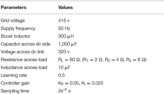
Table A1. Parameters of the system.
Keywords: Adaline-based LMS, multi-level inverter, recursive least square, total harmonic distortion, power quality
Citation: Das SR, Ray PK, Sahoo AK, Balasubramanian K and Reddy GS (2020) Improvement of Power Quality in a Three-Phase System Using an Adaline-Based Multilevel Inverter. Front. Energy Res. 8:23. doi: 10.3389/fenrg.2020.00023
Received: 31 December 2019; Accepted: 06 February 2020;
Published: 28 February 2020.
Edited by:
Sudhakar Babu Thanikanti, Universiti Tenaga Nasional, MalaysiaReviewed by:
Marif Daula Siddique, University of Malaya, MalaysiaCopyright © 2020 Das, Ray, Sahoo, Balasubramanian and Reddy. This is an open-access article distributed under the terms of the Creative Commons Attribution License (CC BY). The use, distribution or reproduction in other forums is permitted, provided the original author(s) and the copyright owner(s) are credited and that the original publication in this journal is cited, in accordance with accepted academic practice. No use, distribution or reproduction is permitted which does not comply with these terms.
*Correspondence: Arun Kumar Sahoo, YXJ1bnNhaG9vODlAZ21haWwuY29t
Disclaimer: All claims expressed in this article are solely those of the authors and do not necessarily represent those of their affiliated organizations, or those of the publisher, the editors and the reviewers. Any product that may be evaluated in this article or claim that may be made by its manufacturer is not guaranteed or endorsed by the publisher.
Research integrity at Frontiers
Learn more about the work of our research integrity team to safeguard the quality of each article we publish.