 Jinchen Gao
 Yanwei Yue3
 Zhaoming Meng
 Xiaoyu Li
95% of researchers rate our articles as excellent or good
Learn more about the work of our research integrity team to safeguard the quality of each article we publish.
Find out more
BRIEF RESEARCH REPORT article
Front. Energy Res. , 20 February 2020
Sec. Nuclear Energy
Volume 8 - 2020 | https://doi.org/10.3389/fenrg.2020.00008
This article is part of the Research Topic Advances in Nuclear Power Engineering View all 20 articles
The influence of the size and the angle of the branch on the onset of gas entrainment is explored in the present study. Since previous studies were performed on small-sized branches and the angles of the branches were specific (0° or −90°), it is difficult to apply them to arbitrary-angled branches. So we conducted a series of experiments in a different direction of −30°, −45°, −60°, and −90° angles with the main pipe of 80-mm diameter and a branch of 31-mm diameter (T-tube). A new correlation is developed and can predict the most experimental data well within the error range of ±20%. And the new correlation can predict the onset of gas entrainment at arbitrary-angled branch and is not constrained by the angle of branches; that is, it has good versatility. We also gained some meaningful conclusions by analyzing experimental data and the entrainment phenomenon: gas is entrained by a vortex flow, and the size of the branch and the angle of the branch have little effect on the form of entrainment at a given hb/d. The critical Froude number (FrL) gradually increases as the angle of the branch changes from −90° to −30°. When this is compared with previous models, it can be found that the correlation of the onset of gas entrainment based on small-sized branches is not suitable for large-scale branches. But we have defined a new critical liquid level () to successfully expand the scope of application of the correlation.
In the AP1000 reactor of the third-generation nuclear power plant, the T-tube structure is widely used in the pipeline of the fourth-stage automatic depressurization system (ADS-4) and the passive residual heat removal system (PRHRS) (Schulz, 2008; Lin, 2010). Zuber (1980) pointed out that for the T-tube structure, when the gas–liquid stratified flow exists in the horizontal main pipe, the relative position of the branch/break and the gas–liquid interface will cause two different entrainment phenomena. If the branch/break location is below the gas–water interface, the gas may be entrained by the continuous liquid stream through the branch/break, causing gas entrainment. Conversely, if the branch/break location is above the interface, the liquid may be entrained by the continuous gas stream through the branch/break, causing liquid entrainment. During loss-of-coolant accidents (LOCAs), gas entrainment may occur at the location of the break below the horizontal interface. In a pressurized water reactor (PWR), gas entrainment may cause failure of residual heat removal pump (Guide, 1989). Therefore, it is of great engineering value to study the gas entrainment phenomenon.
In the previous work, numerous models of onset of gas entrainment were used in various analytical procedures for analyzing PWR safety accidents. According to the relevant parameters, Zuber (1980) established a simplified correlation for the entrainment through the top, bottom, and side branches:
where Frb = [(4/π)Wb]/[gd5ρb(ρL – ρG)]0.5, Wb is the continuous phase mass flow in the branch, ρL is the density of the liquid, ρG is the density of the gas, d is the inner diameter of the branch/break, and the coefficients C1 and C2 are determined by experimental data. Smoglie C. from KfK (Smoglie and Reimann, 1984) used point-sink analysis to establish a model that predicts the onset of entrainment at the top, bottom, and side branches, ignoring the effects of liquid viscosity and surface tension.
where K is obtained by fitting the experimental data. However, the direction of the branch/break is not limited to three (top, bottom, and side). Based on the assumption of inertial force and gravity balance, Lee et al. (2006) developed a correlation that can predict the onset of gas entrainment at arbitrary-angled branches (−30°, −45°, −60°, and −90°):
where Δρ = ρL – ρG, COGE(θ) is determined by the value of θ, and the Froude number (FrL) is defined by the volume flow rate (Q) at the branch entrance.
Since the coefficient COGE(θ) is a function of θ, the model is not very versatile. Taking into account the influence of the size of the branches on gas entrainment, Shen et al. (2018) performed a gas entrainment experiment for large-sized (d/D = 0.625) and small-sized (d/D = 0.125) vertical downward branches; in addition, a new correlation has been established:
where the value C = 1.17 was obtained by fitting the experimental data. Most of the above models are for small-sized branches. However, some researchers have found that models used to predict liquid entrainment through small-scale branches are not suitable for large-scale branches (Riemke et al., 2006; Welter et al., 2014). Therefore, we have reason to doubt whether the model used to predict gas entrainment through small-scale branches is suitable for large-scale branches.
For the onset of gas entrainment, the above studies, except Lee's, are only for vertical downward branches/break. However, in practice, the branch/break may appear anywhere (below the horizontal). Therefore, to meet the engineering needs and also to verify whether Lee's model is suitable for this experiment, the experiment of onset of gas entrainment through large-sized branches at an arbitrary angle (−90°, −60°, −45°, and −30°) is carried out in this paper. The angle of the branch (θ) is defined as the angle between the branch and the horizontal plane (below the horizontal). Using visualization equipment, this paper aims to investigate the effect of the size of the branch and the angle of the branch on the onset of gas entrainment and develop a more universal correlation for the prediction of onset of gas entrainment.
The test bench of this experiment includes a water tank, air–water separator, water pump, horizontal pipe with a diameter of 80 mm, and branch pipe with a diameter of 31 mm, as shown in Figure 1. The total length of the test section is 2,570 mm, of which the upstream is 1,730 mm and the downstream is 840 mm. At the T-joint, the branch pipe can be disassembled for the convenience of changing the angle of the branch.
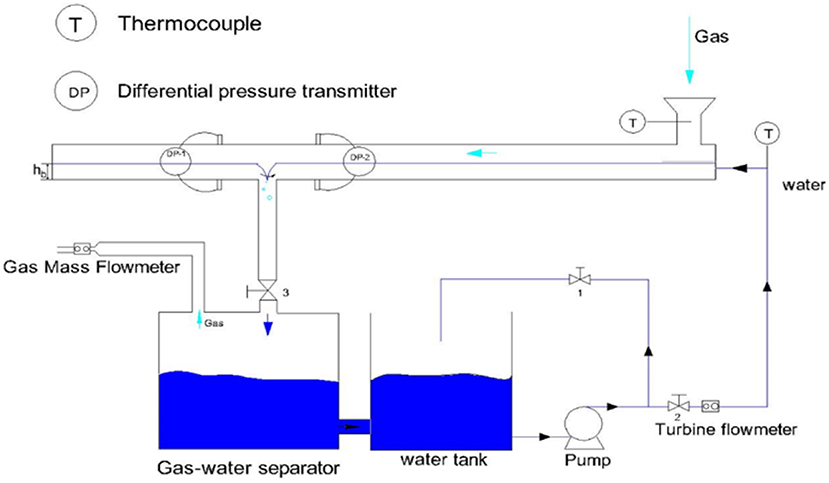
Figure 1. Schematic diagram of the test facility.
Water flow is supplied by a pump and measured by a turbine flow meter (accuracy of 0.2%, measurement range of 0–6 m3/h). At the end of the gas–water separator, the entrained gas is measured by a micro-gas mass flow meter (accuracy of 0.2%, measurement range of 0–5 L/min). In addition, differential pressure transmitters (accuracy of 0.05%, measurement range of 0–0.17 kPa) are installed before and after the T-joint to measure the pressure difference between the two-phase interface and the bottom of the main pipe, to calculate the liquid level height. The temperatures of gas and water are measured by the thermocouple (accuracy of 0.5°C, measurement range of 0–350°C).
(1) Open the centrifugal pump water supply, and regulate gate valves 1 and 2 to ensure the liquid mass flow to reach a certain value and to make the level in the horizontal main pipe rise to a certain height.
(2) When gate valve 3 is regulated, the horizontal interface in the main pipe decreases slowly (<1 mm/min). When a vortex is formed in the liquid phase and a very thin tube reaches the branch entrance, the gas entrainment occurs (i.e., OGE). At this time, the liquid phase height in the main pipe is hb.
(3) Change the mass flow rate of liquid, and repeat steps (1) and (2).
(4) Change the angle (θ) between the branch pipe and the horizontal plane, and repeat steps (1)–(3).
By Equation (6), the mass flow rate of the liquid in the branch (W3L) can be calculated by the mass flow rate of the liquid in the main pipe (W1L) measured by the turbine flow meter.
where M represents the water mass in the main pipe, which is related to main pipe diameter and water level h. dM/dt indicates the rate of change in water mass obtained by changing the water level (h) in the main pipe. In order to ensure that W1L and W3L are approximately equal, it is necessary to control the water level in the main pipe (h) to drop very slowly (<1 mm/min), so it can be assumed that the liquid level in the main pipe is constant during a certain period. Therefore, it can be assumed that the experiment is in a steady state.
The phenomenon of gas entrainment for the bottom branch can be observed as follows: at a given liquid flow rate and water level, a smaller vortex is formed, which will quickly disappear due to buoyancy; after a long time, another large vortex is formed, and the gas tube will gradually become longer, and with the slow decrease of the interface (<1 mm/min), the formation of the vortex becomes more and more frequent. A curved fine gas tube with a big vortex extends to the branch pipe, which is defined as the onset of the gas entrainment.
The development of onset phenomena for the branch with an angle of −60° is the same as that for the bottom branch. Furthermore, for the branches with an angle of −45° and −30°, the development of onset phenomena is the same as that for the bottom branch.
In Figure 2A, at a given hb/d, the critical Froude number (Frf) gradually increases as the angle of the branch changes from −90° to −30°. On the one hand, according to the mechanism of gas entrainment, the bubble can be entrained into the branch pipe, which is due to the inertial force of the bubble to overcome its buoyancy. At a given hb/d and Froude number (Frf), as the angle of the branch increases (from −90° to −30°), the component of the inertial force of the bubble reduces in a vertical downward direction (see Figure 2B). When the gas entrainment occurs, in order to overcome the buoyancy of the bubble, the inertial force component of the bubble in the vertical downward direction needs to be increased, so the Froude number (Frf) needs to be increased. On the other hand, the friction on the inner wall surface of the main pipe can hinder the formation of the vortex. At a given hb/d and Froude number (Frf), as the angle of the branch increases (from −90° to −30°), the position of the vortex gradually approaches to the inner wall surface of the main pipe (see Figure 2C), and the formation of vortex is increasingly affected by the friction force (the effect of wall curvature) (Lee et al., 2007; Wang et al., 2011). Hence, when gas entrainment occurs, in order to overcome the buoyancy of the bubble and the wall friction resistance, the liquid velocity (V2L) of the horizontal main pipe increases with the gradually increasing angle of the branch pipe, so the liquid velocity (V3L) of the branch also increases and the Froude number (Frf) gradually increases.
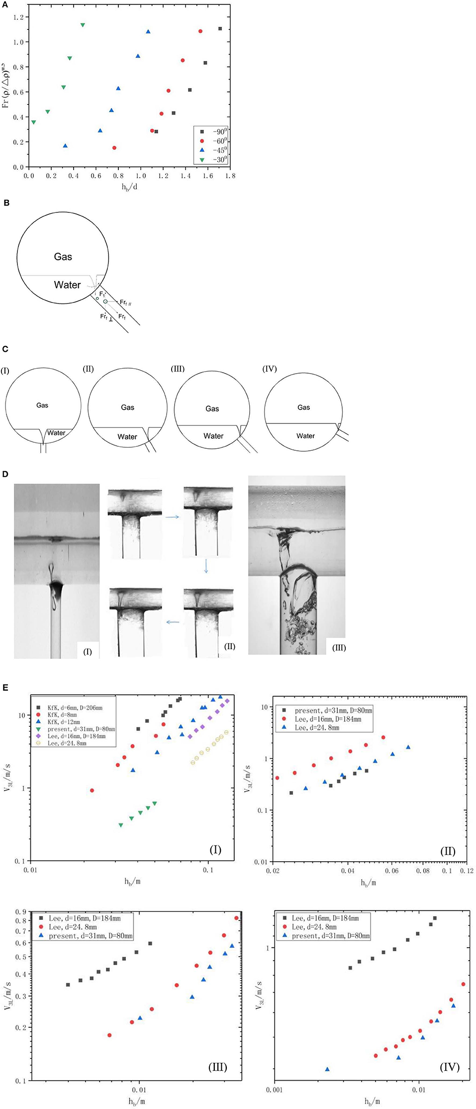
Figure 2. The phenomenon and influencing factors of gas entrainment. (A) The OGE data at −30°, −45°, −60°, −90° branches. (B) Force diagram of bubbles. (C) Vortex position, (I) θ = −90°, (II) θ = −60°, (III) θ = −45°, and (IV) θ = −30°. (D) Onset phenomenon at arbitrary-sized branches, (I) d = 10 mm (Shen et al., 2018), (II) d = 31 mm, and (III) d = 50 mm (Shen et al., 2018). (E) Comparison of present OGE data with KfK and Lee, (I) θ = −90°, (II) θ = −60°, (III) θ = −45°, and (IV) θ = −30°.
In Figure 2D, comparing Shen's (Lee et al., 2006) phenomenon of onset entrainment, for the bottom branch, although only the size of the branch is different, the form of onset entrainment all belongs to vortex entrainment, and a thin curved gas tube extends to the branch. Of course, the phenomenon of onset entrainment is still different due to the influence of the geometrical size of the branch. For the branch with a diameter of 50 mm, a distinct gas chamber exists in the entrance of the branch [Figure 2D (III)]. The reason is that the shape of the vortex generated at the entrance of the large-sized branch is larger than that generated at the entrance of the small-sized branch. Therefore, for the large-sized branch, when some bubbles with large volume enter the branch, with the effect of the buoyancy force of the bubbles, these bubbles cannot be entrained into the steam–water separator but gather to the entrance of the branch to form a gas chamber.
In Figure 2E, the experimental data of Lee, KfK, and Shen are compared with the present experimental data. For arbitrary-angled branch pipes, at a given critical liquid velocity of branch (V3L), hb decreases as the size of branch pipe decreases. The reason is that the local resistance coefficient at the entrance of the small-sized branch pipe is larger than that at the entrance of the large-sized branch pipe. At a given liquid velocity of the branch pipe (V3L), the local resistance at the entrance of the small-sized branch is greater than the local resistance at the entrance of the large-sized branch pipe. According to the Bernoulli effect, under a given liquid velocity of the branch pipe (V3L), for small-sized branch pipes, the dynamic pressure is greatly affected by the local resistance, which causes the static pressure difference from the inner interface of the main pipe to the branch pipe to reduce. Hence, when gas entrainment occurs, the critical liquid level (hb) is smaller.
Based on the model of Lee et al., we made some modifications to build a more adaptable model. It is assumed that the gas–water in the main pipe is a two-phase stratified flow, and the liquid phase is an incompressible fluid and ignores the viscosity and surface tension of the liquid.
In Figure 3A, schematics for the onset of gas entrainment is shown. For −90° ≤ θ < 0°, it is known from the experimental phenomena that when gas entrainment occurs, a fine gas tube always extends to the upper edge of the branch. Hence, in this study, h1OGE is defined as the vertical height between the gas–water interface and the upper edge of the branch, rather than the vertical distance between the gas–water interface and the center of the branch (hOGE), which is different from the definition of Lee et al. (2006, 2007).
The Froude number used in this study is the same as that of Lee et al.; we can get the following definition of the Froude number:
where Q is the volume flow rate of the liquid.
Inserting Equation (7) into Equation (3), we can get the following correlation:
Since Frf is nonlinearly related to hOGE/d and is related to the angle of the branch, the correlation is corrected by a sine function. For −90° ≤ θ < 0°, we can get the following correlation:
By fitting Equation (10) with the present experimental data, we can get the optimal solutions for COGE(θ) = 0.283, k = 1.149, m = 3.224, and n = 0.935.
In Figure 3B, the simulated curve and the present experimental data are shown. For arbitrary-sized branches, such as −90°, −60°, −45°, and −30°, the experimental data are scattered on both sides of the simulated curve. In general, the correlation of this experiment can well predict the relationship between the critical Froude number (Frf) and hb/d. Moreover, the experimental data all fall within the error area of ±20%.
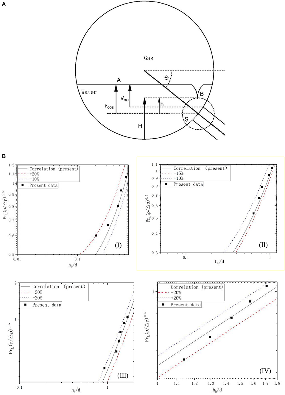
Figure 3. Comparison and definition. (A) Schematics for the onset of gas entrainment. (B) Comparison of present OGE data with KfK and Lee, (I) θ = −30°, (II) θ = −45°, (III) θ = −60°, (IV) θ = −90°.
For the bottom branch, some studies and correlation predictions were made for the onset of gas entrainment. Figure 4 (I) represents the comparison of the experimental data and the correlations of previous and present researchers. For the onset of vortex-induced gas pull-through, the correlation of KfK (Equation 2) accurately predicts the data of the onset of gas entrainment for a range of 0.029 < d/D < 0.135 (Smoglie and Reimann, 1984; Guide, 1989). And for this study, the present data are all within ±20% of the region. In other words, the model of KfK can predict the results of this study well. It is proved that the effective application range of the KfK model can be extended to 0.029 < d/D < 0.388 for the entrainment through a bottom branch.
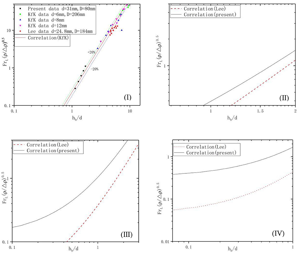
Figure 4. Comparison of present data correlation and KfK and Lee correlations, (I) θ = −90°, (II) θ = −60°, (III) θ = −45°, and (IV) θ = −30°.
Figure 4 (II, III, and IV) shows the comparison between Lee correlation and present correlation. For other tilted branches, such as −60°, −45°, and −30°, Lee's correlation curve is significantly different from the correlation curve of this experiment. The reason is that the size of branch of this experiment is different from that of Lee. Since d/D < 0.14 in Lee's experiment, the effect of the size of the branch on the gas entrainment can be ignored when defining hOGE. However, the size of the branch (d/D = 0.385) in this experiment is larger than that of Lee, so the influence of the size of the branch pipe on the gas entrainment cannot be ignored. After considering the effect of the size of the branch, we redefine h1OGE as the vertical height between the two-phase interface and the upper edge of the branch, rather than the vertical distance between the two-phase interface and the center of the branch, which explains the difference between our correlation and the correlation of Lee et al.
In this study, the experiment on onset of gas entrainment was carried out in different directions of −30°, −45°, −60°, and −90° through a branch with a diameter of 31 mm. And we have established a new correlation to predict the onset of the gas entrainment in arbitrary directions (d/D = 0.375, θ = [−30°, −45°, −60°, −90°]). By analyzing experimental data and experimental phenomena, the main conclusions are as follows:
(1) The gas is entrained by vortex flow, and the size of the branch and the angle of the branch have little effect on the form of entrainment. However, due to the effect of the branch diameter, when the gas is entrained through the 50-mm branch, there is a gas chamber at the inlet of the branch pipe.
(2) The new correlation established in this paper can predict the experimental data well, and the maximum error is ±20%.
(3) By comparison with Lee's model, it can be found that the model of onset of gas entrainment based on small-sized branches is not suitable for large-scale branches. This is because the model of Lee does not consider the influence of the diameter of the branch. To solve this problem, we have defined the new critical liquid level (h1OGE).
All datasets generated for this study are included in the article/supplementary material.
JG and ZM participated in the design of this study, and they both contributed significantly to analysis and manuscript preparation. YY and GS helped perform the analysis with constructive discussions. XL and GS carried out the study and collected important background information. JG performed the data analyses and wrote the manuscript. All authors read and approved the final manuscript.
YY was employed by the company China Nuclear Power Engineering Co.
The remaining authors declare that the research was conducted in the absence of any commercial or financial relationships that could be construed as a potential conflict of interest.
The financial supports of the National Nature Science Foundation of China (nos. 11605032 and 11605033), the Fundamental Research Funds for Central University of Ministry of Education of China (3072019CF1506), and the Innovation Fund of the Fundamental Research Funds for the Central Universities (3072019GIP1520) are gratefully acknowledged. I would also like to thank YY for his important guidance in this process, whose contribution is equivalent to that of the first author.
Guide, R. (1989). Best Estimate Calculations of Emergency Core Cooling System Performance. Washington, DC: US Nuclear Regulatory Commission.
Lee, J. Y., Hwang, G. S., Kim, M., and No, H. C. (2006). Experimental analysis of off-take phenomena at the header–feeder system of CANDU. Ann. Nucl. Energy 33, 3–8. doi: 10.1016/j.anucene.2005.09.002
Lee, J. Y., Hwang, S. H., Kim, M., and Park, G. C. (2007). Onset condition of gas and liquid entrainment at an inclined branch pipe on a horizontal header. Nucl. Eng. Des. 237, 1046–1054. doi: 10.1016/j.nucengdes.2007.01.002
Riemke, R. A., Bayless, P. D., and Modro, S. M. (2006). “Recent improvements to the RELAP5-3D code,” in Proceedings of the 2006 International Congress on Advances in Nuclear Power Plants, ICAPP'06. Reno, NV. 1816–1819.
Schulz, T. L. (2008). Westinghouse AP1000 advanced passive plant. Nucl. Eng. Des. 236, 1547–1557. doi: 10.1016/j.nucengdes.2006.03.049
Shen, K., etal. (2018). Study on Gas Entrainment in Vertical Downward T-tube[D]. Harbin: Harbin Engineering University, 22–24. (in Chinese).
Smoglie, C., and Reimann, J. (1984). Two-phase flow through small branches in a horizontal pipe with stratified flow. Int. J. Multiphase Flow 12, 609–625. doi: 10.1016/0301-9322(86)90063-7
Wang, W., Su, G., Qiu, S. Z., and Tian, X. W. (2011). Thermal hydraulic phenomena related to small break LOCAs in AP1000. Prog. Nucl. Energy. 53, 407–419. doi: 10.1016/j.pnucene.2011.02.007
Welter, K. B., Wu, Q., You, Y., Abel, K., McCreary, D., Bajorek, S., M., et al. (2014). Experimental investigation and theoretical modeling of liquid entrainment in a horizontal tee with a vertical-up branch. Int. J. Multiphase Flow 30, 1451–1484. doi: 10.1016/j.ijmultiphaseflow.2004.08.001
Zuber, N. (1980). Problems in Modeling of Small Break LOCA. Technial Report, Nuclear Regulatory Commission. Washington, DC: Division of Reactor Safety Research.
Keywords: T-tube, onset of gas entrainment, size of branch, angle of branch, the onset of phenomenon
Citation: Gao J, Yue Y, Meng Z, Li X and Shen G (2020) Influence of the Size and the Angle of Branches Connected to the Main Horizontal Pipe on the Onset of Gas Entrainment. Front. Energy Res. 8:8. doi: 10.3389/fenrg.2020.00008
Received: 20 October 2019; Accepted: 13 January 2020;
Published: 20 February 2020.
Edited by:
Bruno Panella, Politecnico di Torino, ItalyReviewed by:
Keyou S. Mao, Purdue University, United StatesCopyright © 2020 Gao, Yue, Meng, Li and Shen. This is an open-access article distributed under the terms of the Creative Commons Attribution License (CC BY). The use, distribution or reproduction in other forums is permitted, provided the original author(s) and the copyright owner(s) are credited and that the original publication in this journal is cited, in accordance with accepted academic practice. No use, distribution or reproduction is permitted which does not comply with these terms.
*Correspondence: Zhaoming Meng, bWVuZ3poYW9taW5nQGhyYmV1LmVkdS5jbg==
Disclaimer: All claims expressed in this article are solely those of the authors and do not necessarily represent those of their affiliated organizations, or those of the publisher, the editors and the reviewers. Any product that may be evaluated in this article or claim that may be made by its manufacturer is not guaranteed or endorsed by the publisher.
Research integrity at Frontiers
Learn more about the work of our research integrity team to safeguard the quality of each article we publish.