 Jian Zhou
 Ming Ding
95% of researchers rate our articles as excellent or good
Learn more about the work of our research integrity team to safeguard the quality of each article we publish.
Find out more
ORIGINAL RESEARCH article
Front. Energy Res. , 07 June 2018
Sec. Nuclear Energy
Volume 6 - 2018 | https://doi.org/10.3389/fenrg.2018.00035
This article is part of the Research Topic Nuclear Thermal Hydraulic and Two-Phase Flow View all 13 articles
Compact parallel manifolds are widely applied in flow heat exchangers. However, the flow maldistribution exists in the parallel manifolds when the flow is distributed in the header, because of the pressure maldistribution. For a heat exchanger, the uniformity of the flow distribution greatly influence the performance of the heat exchanger. It is significantly important to modify the design of the heat exchanger for a uniform flow distribution. In present study, to reduce the maldistribution in the manifolds, the numerical analysis has been made and a method by varying the insert length of tubes inside the header has been pointed out to solve this problem of flow maldistribution. To illustrate the reliability of this method to reduce the maldistribution, three base cases with different header diameters have been applied to be solved with the method. The results indicates that, by using the method, the maldistribution for three base cases can be reduced by 82% for the case1, 72% for the case2 and 68% for the case3. However, the insert length of tubes inside the header increases more pressure loss. The pressure drop for base cases are respectively increased by 2.83, 4.83, and 6.46%. This method is proved to be effective under all flow rates.
Central-type compact parallel flow heat exchangers are used for removing the heat and ensure the safety of the system. These manifolds are widely applied in cooling systems such as passive containment cooling system of the pressure water reactor, spargers, electronic cooling equipment, and passive core cooling system.
However, the mass flow maldistribution occurred in the heat exchanger greatly reduces the heat transfer performance. Besides, the variations of heat transfer performance caused by maldistribution result in deviations from desired design performance, which may cause that the heat exchanger could not meet the need of the design performance in the practical application.
The flow maldistribution existed in the heat exchanger is caused by the pressure distribution in the header, therefore, the maldistribution in parallel manifolds is an inherent characteristic of the heat exchanger. The way to flatten the flow distribution could be flattening the pressure distribution.
For instance, when dealing with tubes, Said et al. (2014) successfully reduced the maldistribution in a central-type heat exchanger with the method of applying orifice approach and nozzle approach in tubes respectively. Huang and Wang (2013) have done the investigation of design of uniform tube flow rates in a Z-type heat exchanger. Levenberg-Marquardt Method (LMM) was applied to decide the estimated optimal tube diameters and entrance length of the inlet. And the results showed that the flow distribution was nearly uniform. Tong et al. (2007) have applied gate-valve-like obstructions in manifolds in order to tailor the resistance of an individual channel to achieve a uniform distribution. And results showed that this method worked well, for example, in one of the case studies, the original flow imbalance of the untailored manifold system exceeded 100% and was reduced to less than 10% of the flow imbalance in one cycle of the method. In another study of Tong et al. (2009), the cross-sectional areas of the outflow channels have been modified in linear tapering or non-linear tapering, and results showed that the flow distribution become uniform after solutions were carried out.
As for the promotion of the header design, in the study by Wang et al. (2011b), five modified headers have been investigated, the results showed that the baffle tube performed best and it was applicable for all the flow rates. Wang et al. (2014) have proposed a numerical model of plate-fin heat exchanger to investigate the hydrodynamic characteristics with the method of applying porous media approach in the header. The results showed that the flow distribution was promoted and a correlation among maldistribution, pressure drop, and Reynolds number was derived based on the simulation. Similarly, a uniformly perforated grid has been used in the header of a cross flow heat exchanger in the study of Lalota et al. (1999) They reported that the grid was helpful to improve the fluid distribution.
Except for the promotion of structure for heat exchanger configuration, the influence of the structure parameters on the flow distribution has also been investigated. Gandhi et al. (2012) have done a lot of investigations on the influence made by configuration parameters on the flow distribution. According to their study, the tube diameter, number of tubes and the location of the inlet and outlet pipe are the key configuration parameters affecting the flow distribution. They also have done the experiments to validate simulation results. Bajura and Jones (1976) suggested that the area ratio(AR) < 1 for the parameter design. And Tong et al. (2009) found that enlarging the header diameter for increasing the flow ratio will help improve the flow distribution. Wang et al. (2011a) have done the investigations on the compact parallel flow heat exchangers. According to their studies, the uneven flow distribution is related to following parameters: (1) inlet flow condition, (2) tube diameter, (3) header diamter, (4) area ratio, (5) flow directions. And the effect of gravity is insignificant.
There is also some analytical method to investigate the flow distribution in the heat exchanger. Wang and Wang (2015) have developed a discrete model for flow uniformity and pressure drop in U-type arrangement as well as Z-type arrangement. The results show that the flow distribution in U-type arrangement is generally better than that of the Z-type in cases for large mass flow rate and small pressure drop coefficients. Tong et al. (Sparrow et al., 2007) set forth a quasi-analytical method which is fully validated for determining the flow distribution in multi-inlet collection manifold. And this method can help design a manifold in which the flow distribution is nearly uniform.
In the past studies, researchers focus on the optimization of the flow distribution in compact parallel flow heat exchangers, and a lot of valuable results have been obtained. However, little work has been done on tubes. Besides, it could be more easier and convenient to even the flow distribution with the modification with tubes. In this study, the attention are paid on the modification of tubes. For a conventional configuration of heat exchanger, the header and heat transfer tubes are seamlessly connected as shown in Figure 1A. However, this conventional design does not perform well because of the pressure maldistribution in the header. The modification of the tube in this study is applied to decrease the pressure malsitribution at the inlet of the tubes as shown in Figure 1B. The tubes are not connected to the header surface, but inserted inside the header. Besides, the insert length of tubes are not equal thus evening the pressure distribution at the inlet of tubes for a better flow distribution.
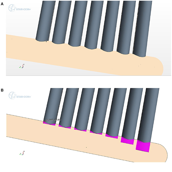
Figure 1. (A) The conventional design. (B) The promotion of tubes.
The main objective of this study is to search for a better flow distribution in a central-type compact parallel flow heat exchanger. Therefore, three basic configurations of exchangers with different headers as well as different flow distributions are applied of analysis. The three-dimensional model and schematic diagram of the configuration for this study are shown in Figure 2. Configuration models consist of two headers called dividing header and combining header respectively and 14 C-tubes are connected to the headers. The working fluid flows into dividing header and then is divided into 14 branches of flow through 14 C-tubes combining in the combining header at last.
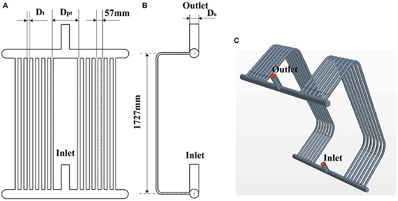
Figure 2. The three-dimensional model and schematic diagram of the subject (A) schematic diagram of the subject (B) side view of the subject (C) the three-dimensional mode.
Three optimization based on three basic configurations with different size of headers are solved respectively. Three header diameters are 60, 80, and 100mm respectively denoted case1, case2 and case3. The objective of the problem is to vary the insert length of the tube inside the header for a better flow distribution as shown in Figure 3. Therefore, three different basic configurations with different diameters of headers are solved to determine the basic flow distribution. Based on the basic configuration, the insert of tubes are introduced to reduce the flow maldistribution. The problem is iteratively solved after each adjustment of insert length to produce a more even flow distribution. The iterations are finished until the flow distribution is basically no longer better by changing the insert length of tubes.
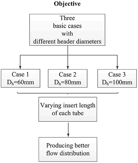
Figure 3. The objective of the solution.
The CAD in the Star-ccm+ is used to create the heat exchanger model. Two different kinds of mesh elements are applied for the proper meshing of the whole geometry. The polyhedral mesh is applied to mesh headers, inlet, outlet and part of the C-tubes, and the rest of the C-tubes is meshed with generalized cylinder mesh. Besides, the prism layer model is used for all of the geometry walls to solve the boundary conditions as shown in Figure 4.
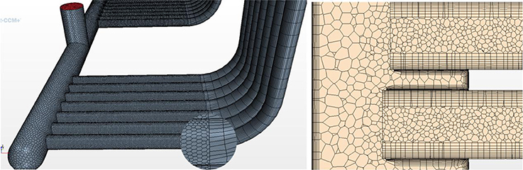
Figure 4. The mesh applied in the geometry mode.
Star-ccm+ 10.04 software is applied to complete the simulation and constraints described by the boundary of a given system have been applied to solve the control equations for mass and momentum. The resulting partial differential equations together with a high turbulence model are solved numerically.
For the boundary conditions, velocity-inlet is chosen for the inlet, pressure-outlet selected for the outlet is set as zero gauge pressure and the walls are set as no slip condition and rough. The k–ε turbulent model is chosen as the turbulence model.When all of the residuals are less than 1 × 10⁻³, solutions are considered to be completely convergent.
In this study, water has been selected as the working fluid. Three assumptions have been made for the system as following listed.
(1) The wall is set to isothermal.The heat exchange is beyond the consideration in this study.
(2) No phase change happens inside the system because the heat exchange is out of the consideration.
(3) Density change is considered negligible and flow is considered incompressible.
To evaluate the flow distribution, dimensionless parameter SE has been utilized.
Where the mi and mav represent the mass flow rate through the ith tube and the average mass flow rate respectively. And the M represents the total flow rate.
The steady-state continuity equation is written as
The steady-state momentum conservation equation is written as
The steady-state transport equation for k is written as
The steady-state transport equation for ε is written as
Where the k and ε represent the turbulent kinetic energy and turbulent energy dissipation rate, respectively. ρ is the density of the working fluid, u is the velocity, turbulent constants σk = 1.0 and σε = 1.3 are used and μt means turbulent dynamic viscosity. Empirical constants C1 = 1.44, C2 = 1.92 are used.
As for the grid independence, four different number of grids are applied on the geometry. The number of grids are 2,365,663; 2,941,239; 4,539,910; 7,925,274 and denoted respectively as mesh1, mesh2, mesh3, and mesh4. Because the two most important objectives in this study are flow distribution and pressure drop, the evaluation criteria of the performance of the grid is based on the value of SE and the pressure drop in simulation results. The mass flow rate through 14 tubes is shown in the Figure 5. It can be seen that, the significant change of results stops when the number of grid elements increases to the mesh2. Therefore, mesh2 is chosen as the independent mesh size.

Figure 5. Grid independence test.
The experimental data from Gandhi et al. (2012) was used to validate the numerical results in present study. Gandhi et al. (2012) used 10 tubes with a cylindrical header and an inlet nozzle whereas in the present study, 14 tubes, two headers, an inlet nozzle and a outlet nozzle are used. However, the rest of the geometry is similar. Besides, in both studies, the water was used as the working fluid. Except for experiments, Gandhi et al. (2012) also has done the numerical work based on commercial software Fluent (version 6.2.16) and three different inlet velocities have been applied. Both of the numerical and experimental results done by Gandhi et al. (2012) as well as simulation results in present study are shown in Figure 6. It can be seen that the simulation for the present study suits well, and the results of the further work made by the simulation in this study are credible.
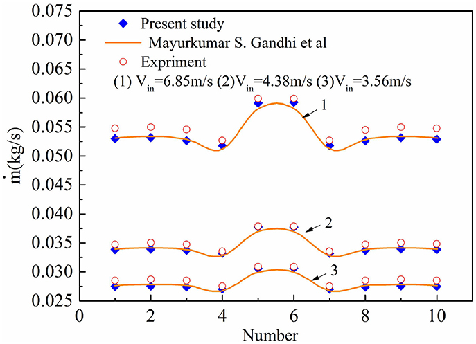
Figure 6. The validation of the simulation results.
Basic equations for header and tubes have been separately formulated. In equations, the velocity and static pressure all represent average values. The configuration of dividing header and connected tubes are shown in Figure 7. For the control volume of the header section at the inlet of the ith tube, it is enclosed up with a dotted line as shown in Figure 7.
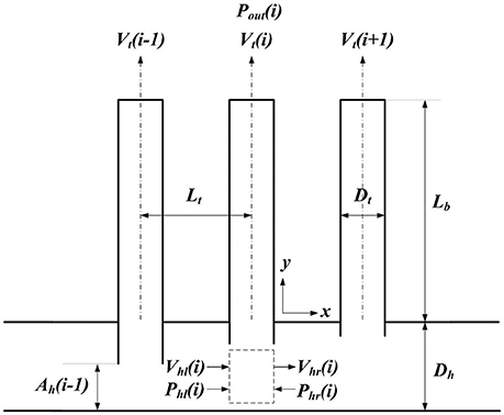
Figure 7. Configuration of a dividing flow manifold.
The Bernoulli equation for the flow in the tube is written as
Where Ct represents local friction coefficient of tubes, for example, that caused by vortex flow at the tube inlet. Cb represents bend loss coefficient. And Ctd represents inlet friction coefficient of tubes.
The continuity equation is written as
Where Ah(i)and At represents effective flow cross section area of the header in front of the ithtube and the tube cross section area respectively. Besides, ρh equals to ρt, considering the assumption of incompressible flow.
The Equations (6, 7) show the influential parameters for the velocity in tubes. The way to achieve a uniform distribution lays on the adjustment of these influential parameters. For a certain heat exchanger with fixed structure parameters. The most effective and direct method is to vary the Ah(i) for each tube as shown in Equation (7). In addition, the variation of Ah(i) will unequally change friction coefficients such as Ct and Ctd as well as pressure distribution in the header, which means that the influence of the insert length for each tube is not equal.
For compact parallel flow heat exchangers, the dynamic pressure is higher near the center of header, while the static pressure is higher near the edge, because of the influence of pressure recovery. Therefore, the sensitivity of variable insert is higher at the header center. And this will help save time for the iteration work.
The insert length of each tube for three cases with the best solution is listed in Table 1.
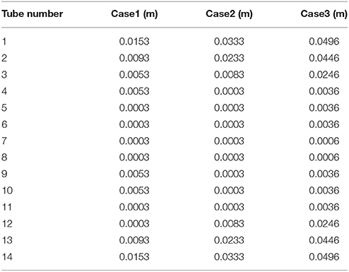
Table 1. The insert length of each tube for three cases with the best solution.
The mass flow rate for three base cases with different header diameters is shown in Figure 8 respectively. The flow patterns of flow distribution on condition of without solution, best case solution and iterative solutions can also be seen in the Figure 8, For the flow distribution of the case1, the mass flow rate is highest at center tubes, and continues to drop until at tube 3 and tube 12 and then increases slightly from tube 3 and tube 12 to the extreme tubes of the header as shown in Figure 8A. Because of the small size of the header, the velocity of the water in the header is high, leading to a high pressure recovery in tubes at the center due to the reduction in velocity in the direction of the mainstream because of the flow into tubes. Therefore, the key to achieve a better flow distribution is to decrease the pressure recovery at the inlet of tubes which high mass flow rate of water flows in. The original process is to increase the extension of the tubes near the inlet inside the header. The extension of the tube inside the header leads to the decrease of the effective flow area above the tube, thus decreasing velocity and the mass flow rate in the tube. Iterative adjustments of variation of the extension for tubes are laid on the analysis discussed above, increasing the extension of tubes where high mass flow is and decreasing the extension of tubes where low mass flow enters. Iterative solutions performed successfully and the best solution are shown in Figure 8A. By comparing the best solution and the base case which is without solution, it can be seen that the mass flow rate in tubes ranging from tube 5 to tube 10 which was high becomes lower and the mass flow rate in the other tubes becomes higher, thus reducing the maldistribution in the header.
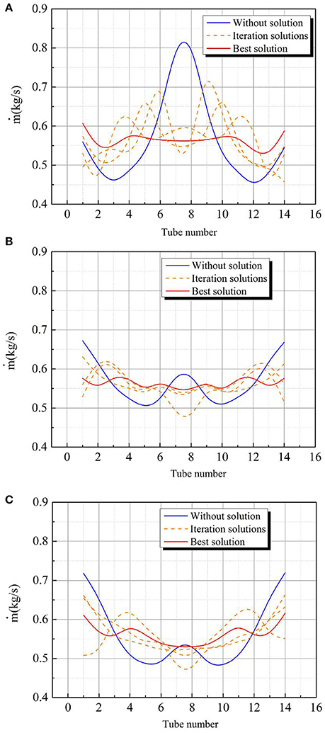
Figure 8. The mass flow rate for three base cases (A) Mass flow rate in tubes for Case 1 (B) Mass flow rate in tubes for Case 2 (C) Mass flow rate in tubes for Case 3.
For the mass flow rate distribution in the tubes of the case2, the maldistribution is better than the case1, the reason is that the bigger cross section area of the header causes the lower velocity of the flow thus leading to a lower pressure recovery and less mass flow rate in center tubes, therefore, the mass flow rate distribution in the case2 is better than that in the case1. In this case, the key to solve this problem is to focus on the tubes at the center and tubes close to extreme ends of the header, in which the mass flow rate is much higher than the average value of mass flow rate in tubes. Based on the analysis discussed before, iterative adjustments of variation of the extension for tubes have been made and the best solution as well as iterative solutions performed successfully is shown in Figure 8B. It can be seen that the mass flow rate in center tubes and tubes close to extreme ends of the header has been successfully decreased making the flow distribution more even.
For the case3, the bigger cross section area of the header than that in case2 continues to decrease the pressure recovery in center tubes leading to even worse flow distribution in the header causing that large amount of mass flow rate goes through tubes which are near extreme edges of the header. For this case, the promotion should be applied to tubes at the extreme edge of the header. The base case without solution, the best solution and iterative solutions performed successfully are shown in the Figure 8C. It can be seen that the flow distribution has been successfully promoted, showing the effectiveness of the method applied in this study.
The method applied in this study all performed well when dealing with these three base cases. The dimensionless parameter SE has been applied to evaluate the maldistribution of the flow distribution in the header. The best solution reduces the SE by 81, 69, and 69% for case1, case2, and case3 respectively. The main concept utilized in the method of reducing the maldistribution is to adjust the effective flow area and the pressure at the tube inlet thus achieving the goal of balancing the mass flow rate through tubes.
The Figure 9 shows the contour diagrams for the static pressure within the header and tubes for all cases under investigation. For all the cases as it can be seen from Figure 9. There is almost a significant pressure drop from the header to the tube for the flow resistance at the interface of the header and tubes. The flow recovery happens at the tube inlet increasing the static pressure in the header. And it can be found that the static pressure increase from the center of the header along the way to the edge of the header. For the cases with the best solution, the pressure gradient in the header and tubes is both smaller than that in the cases without solution. It is because that the different insert length of the tube inside the header promote the pressure distribution. For instance, the pressure at the edge of the header is bigger than other position. The longer extension of the tubes near the extreme edge increase more pressure drop from the header to the tube, thus making the pressure distribution in tubes more uniform.
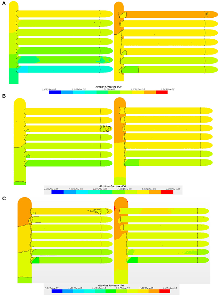
Figure 9. Pressure contour for the header and tubes of heat exchangers (A) Pressure contour for Case 1 (B) Pressure contour for Case 2 (C) Pressure contour for Case 3.
The Figure 10 shows the velocity distribution within the header and tubes for all cases under study. It can be seen in Figure 10A that the flow velocity is bigger inside the tubes near the center of the header while smaller in tubes near edges of the header. With the solution, the extension of tubes near the center decrease the velocity inside these tubes near the center, making the velocity gradient in the header and tubes more uniform as shown in Figure 10B. For the case2 without solution, the velocity in the header near the center and the edge is much higher than that in the middle as shown in Figure 10C. After the solution is applied, the velocity becomes more uniform as shown in Figure 10D. For the case3 with bigger header diameter, the mass flow concentrates in the tubes near the edge, because of low pressure recovery in tubes at the center, pushing more mass flow into tubes at the edge, as shown in Figure 10E. The way should be to increase the extension of tubes near the edge in order to decrease the Ah(i), making the velocity distribution more uniform as shown in Figure 10F.
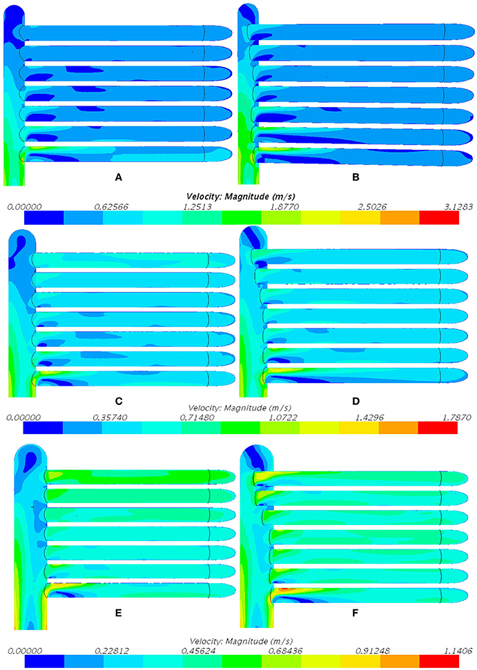
Figure 10. Velocity contour for the header and tubes of heat exchangers (A,B) Velocity contour for Case 1 (C,D) Velocity contour for Case 2 (E,F) Velocity contour for Case 3.
The overall pressure drop through three cases either without or with the best solution are listed in Table 2. Because of the insert length of tubes inside the header, the frictional coefficients increase, bringing more pressure loss. For the best solutions, the pressure drops have been increased by 2.83, 4.83, and 6.46% for case1, case2, and case3 respectively, comparing to the cases without solutions. For the case with smaller header diameter, the velocity in the header is larger. Therefore, the sensitivity of variable insert length is higher and less length of insert length for tubes is needed, which decrease the frictional coefficients brought by the extension of tubes.
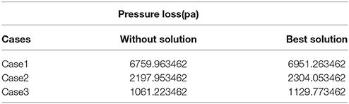
Table 2. The pressure loss for cases from the heat exchanger.
Considering the effect of the mass flow rate on the method in this study, the flow distribution in the case1 without the solution and the case1 with the best solution are numerically calculated under different inlet mass flow rate as shown in Figure 11. As the inlet mass flow rate increase, the maldistribution slightly increase for all cases. Besides, the insert method significantly even the flow distribution under all inlet flow rate, showing that the method is effective and applicable for all inlet flow rates.
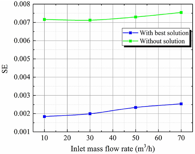
Figure 11. The effect of inlet mass flow rate on the insert method.
A method by varying insert length of tubes has been applied to reduce the flow maldistribution in manifolds of central-type compact parallel flow heat exchangers. The key point of this method is to vary the effective flow area for each tube, adjusting mass flow rate through tubes for a more uniform flow distribution. Three base cases with different header diameters and flow distribution patterns have been used to compare with cases with the best solutions in terms of maldistribution and pressure drop. The results show that the maldistribution in the heat exchanger could be reduced by 81% at most and 69% at least. However, the pressure drop in the heat exchanger is increased by 6.46% at most and 2.83% at least when the header diameter is the largest and smallest respectively.
All authors listed have made a substantial, direct and intellectual contribution to the work, and approved it for publication.
The authors declare that the research was conducted in the absence of any commercial or financial relationships that could be construed as a potential conflict of interest.
Dh, Header diameter; Dt, Tube diameter; Dpt, The pitch between the tubes at the center; SE, Evaluation parameter of flow maldistribution; k, turbulent kinetic energy; ε, turbulent energy dissipation rate; ρ, density of the working fluid; u, velocity; σk, σε, turbulent constants; μt, turbulent dynamic viscosity.
Bajura, R. A., and Jones, E. H. (1976). Flow distribution manifolds. Asme Transac. J. Fluids Eng. 98, 654–665. doi: 10.1115/1.3448441
Gandhi, M. S., Ganguli, A. A., Joshi, J. B., and Vijayan, P. K. (2012). CFD simulation for steam distribution in header and tube assemblies. Chem. Eng. Res. Des. 90, 487–506. doi: 10.1016/j.cherd.2011.08.019
Huang, C. H., and Wang, C. H. (2013). The design of uniform tube flow rates for Z -type compact parallel flow heat exchangers. Int. J. Heat Mass Transf. 57, 608–622. doi: 10.1016/j.ijheatmasstransfer.2012.10.058
Lalota, S., Florentb, P., Langc, S. K. A., and Berglesc, E. (1999). Flow maldistribution in heat exchangers. Appl. Therm. Eng. 19, 847–863.
Said, S. A. M., Mansour, R. B., Habib, M. A., and Siddiqui, M. U. (2014). Reducing the flow mal-distribution in a heat exchanger. Comput. Fluids 107, 1–10. doi: 10.1016/j.compfluid.2014.09.012
Sparrow, E. M., Tong, J. C. K., and Abraham, J. P. (2007). A quasi-analytical method for fluid flow in a multi-inlet collection manifold. J. Fluids Eng. 129, 579–586. doi: 10.1115/1.2717620
Tong, J. C. K., Sparrow, E. M., and Abraham, J. P. (2007). Attainment of flowrate uniformity in the channels that link a distribution manifold to a collection manifold. J. Fluids Eng. 129, 1186–1192. doi: 10.1115/1.2754319
Tong, J. C. K., Sparrow, E. M., and Abraham, J. P. (2009). Geometric strategies for attainment of identical outflows through all of the exit ports of a distribution manifold in a manifold system. Appl. Therm. Eng. 29, 3552–3560. doi: 10.1016/j.applthermaleng.2009.06.010
Wang, C. C., Yang, K. S., Tsai, J. S., and Chen, I. Y. (2011a). Characteristics of flow distribution in compact parallel flow heat exchangers, part I: typical inlet header. Appl. Therm. Eng. 31, 3226–3234. doi: 10.1016/j.applthermaleng.2011.06.004
Wang, C. C., Yang, K. S., Tsai, J. S., and Chen, I. Y. (2011b). Characteristics of flow distribution in compact parallel flow heat exchangers, part II: modified inlet header. Appl. Therm. Eng. 31, 3235–3242. doi: 10.1016/j.applthermaleng.2011.06.003
Wang, J., and Wang, H. (2015). Discrete method for design of flow distribution in manifolds. Appl. Therm. Eng. 89, 927–945. doi: 10.1016/j.applthermaleng.2015.06.069
Keywords: flow maldistribution, pressure maldistribution, manifolds, central-type heat exchanger, uniformity
Citation: Zhou J, Ding M, Meng Z, Zhang Y and Sun Z (2018) Reducing the Flow Distribution in Central-Type Compact Parallel Flow Heat Exchangers Having Optimized Tube Structure. Front. Energy Res. 6:35. doi: 10.3389/fenrg.2018.00035
Received: 13 February 2018; Accepted: 13 April 2018;
Published: 07 June 2018.
Edited by:
Jun Wang, University of Wisconsin-Madison, United StatesReviewed by:
Xianping Zhong, Tsinghua University, ChinaCopyright © 2018 Zhou, Ding, Meng, Zhang and Sun. This is an open-access article distributed under the terms of the Creative Commons Attribution License (CC BY). The use, distribution or reproduction in other forums is permitted, provided the original author(s) and the copyright owner are credited and that the original publication in this journal is cited, in accordance with accepted academic practice. No use, distribution or reproduction is permitted which does not comply with these terms.
*Correspondence: Jian Zhou, emhvdWppYW5AaHJiZXUuZWR1LmNu
Zhongning Sun, c3VuemhvbmduaW5nQGhyYmV1LmVkdS5jbg==
Disclaimer: All claims expressed in this article are solely those of the authors and do not necessarily represent those of their affiliated organizations, or those of the publisher, the editors and the reviewers. Any product that may be evaluated in this article or claim that may be made by its manufacturer is not guaranteed or endorsed by the publisher.
Research integrity at Frontiers
Learn more about the work of our research integrity team to safeguard the quality of each article we publish.