- 1Electric Power Research Institute, CSG EHV Power Transmission Company, Guangzhou, China
- 2State Key Laboratory of Alternate Electrical Power System with Renewable Energy Sources, Beijing, China
Modular Multilevel Converter based High Voltage Direct Current (MMC-HVDC) has been widely used in the large-scale transmission of renewable energy sources (RESs). However, the operating conditions of MMC-HVDC system with RESs are complex and variable, making it challenging to apply a single converter control strategy to different operating conditions, which affects the safe and stable operation of the whole system. In this paper, a flexible switching method of control strategies is proposed for MMC-HVDC converter. Firstly, the state-space model of MMC-HVDC under different control strategies is established, and the small signal stability and stable operation ranges under these control strategies are analyzed. Then, according to the proposed control strategy switching principle, a flexible control switching method for MMC-HVDC converter is proposed. This flexible control switching method ensures a smooth switching between different control strategies and causes a minimal disturbance to the overall system. Finally, a simulation model is established on the PSCAD/EMTDC platform, and the feasibility of the flexible control switching strategy for the MMC-HVDC system is verified. The simulation results show that very small disturbance is observed during the control switching and the flexible control switching strategy can effectively maintain the stable operation of MMC-HVDC system under different operating conditions. The proposed flexible control switching method can be activated according to the change of AC grid strength and it will help improve the stable operation of MMC converter.
1 Introduction
With the acceleration of global energy transformation, the penetration of renewable energy sources (RESs) including wind power and photovoltaic, is gradually increasing. Modular Multilevel Converter based High Voltage Direct Current (MMC-HVDC) can improve the control flexibility and operation reliability of the system and has been widely used in the large-scale transmission of RESs (Ahmed et al., 2011). However, the integration of large amount renewable energy will lead to a wide range of power fluctuation, resulting in a wide variation range of AC system strength (Hao et al., 2022). Faced with variable operating conditions and complex grid structures of AC system, a single control strategy is often insufficient for MMC converter to guarantee a stable operation at all operating conditions, which will pose challenges to the safe and stable operation of the whole AC/DC system (Du et al., 2015).
Currently, Vector Current Control (VCC) is widely used in MMC-HVDC system (Jenny and Gole, 2012; Ling and Fan, 2013). To integrate the renewable energy, the outer loop control of the MMC converter generally adopts P-Q control (active power and reactive power control) strategy or P-V control (active power and AC voltage control) strategy (Barsali et al., 2002; Katiraei and Iravani, 2006). The system stability and control dynamics of MMC-HVDC under P-Q control or P-V control strategies have been extensively studied in literature and several optimal control strategies have been proposed to enhance the system performance. In Hu et al. (2015), Wang et al. (2014), it is found that the interaction between active power control and phase locked loop (PLL) is much increased under weak grid conditions, which will induce instability of the grid-connected system. The eigenvalue analysis in Egea-Alvarez et al. (2015) indicates that the converter using P-V control strategy will be unstable when the grid becomes extremely weak. As a result, an enhanced outer loop based on a decoupled and gain-scheduling controller is proposed to improve the system stability under weak grids. It has been addressed in Ye et al. (2023) that P-Q control strategy has stronger anti-disturbance ability in the face of power fluctuation. While P-V control strategy is more stable under weak grid conditions due to its higher static stability limit. To better handle the power fluctuation of RESs (Ye et al., 2023), further proposes an improved control strategy based on P-Q control incorporating the advantages of P-V control at the same time. The proposed control strategy offers high static stability limits, strong applicability to weak grids, rapid reactive power response and improved anti-disturbance capability compared to the conventional P-V control. However, the above control strategies are designed and operated under given operating condition. The control applicability to different operating conditions is not addressed.
Considering the variable operating conditions of the MMC-HVDC system with integration of RESs, relying on only one converter control strategy makes it difficult to ensure the stable operation of the entire system during changing operating conditions. As a result, several converter control switching strategies have been proposed in the literature to deal with variable operating conditions. A dual-mode inverter control method has been proposed in Peng (2003), where the grid-connected operation is controlled by the P-Q control strategy and island operation is controlled by the V-f control strategy. However, during the switching process, there will be a sudden change in the control references, resulting in voltage and current distortions, which prevents smooth switching between grid-connected and island modes (Wang et al., 2012). The adaptive droop control technology proposed in Vasquez et al. (2009) can effectively achieve seamless switching between grid-connected and island modes. Vasquez et al. (2008) proposes a novel droop control scheme which automatically adjusts its parameters by using an estimation method of the grid impedance based on power variations caused by the voltage source inverter (VSI) at the point of common coupling (PCC). A parallel control strategy switching method between P-Q control and VSG (Virtual Synchronous Generator) control has been proposed in Shi et al. (2016), which can reduce the voltage oscillation and current surge during switching period by tracking the phase angle and current commands simultaneously of the two control modes. But this method does not consider the disturbance caused by changes in grid strength. Based on the traditional control strategies, a VSG/PQ control strategy for grid-connected inverters and a smooth switching method have been proposed in Li et al. (2019), allowing the inverter to work in both VSG and P-Q control mode. However, these references mainly focus on the control switching between grid-connected and island mode, with few studies on the flexible switching of P-Q and P-V control under grid-connected conditions, and there is no clear description of the applicable operating conditions of these control strategies.
Therefore, this paper proposes a flexible switching method between P-Q and P-V control strategies for MMC-HVDC converter based on AC grid strength. Firstly, the state-space model of the MMC-HVDC system under P-Q and P-V control strategies is established, and the small-signal stability and feasible regions of different control strategies are analyzed. Then, based on the control strategy switching principle, a flexible switching method of the control strategy for the MMC-HVDC converter is proposed, ensuring minimal disturbance to the whole system during control switching. Finally, a simulation model is established on the PSCAD/EMTDC platform, verifying the feasibility of the flexible control switching strategy for the MMC-HVDC system.
The rest of this paper is organized as follows. Section II establishes the state-space model of the MMC-HVDC system under P-Q and P-V control strategies. Section III proposes a flexible switching method of the control strategy for the MMC-HVDC converter. Section IV illustrates the verification of the flexible control switching method by simulation, and Section V draws the main conclusions of this paper.
2 Small signal stability of MMC-HVDC under different control strategies
To evaluate the dynamic stability and control applicability of different converter control strategies, the state space model of wind farm integrated MMC-HVDC system under P-Q control and P-V control strategies is established in this section, and their small-signal stability under different operation conditions is analyzed.
2.1 MMC-HVDC system structure
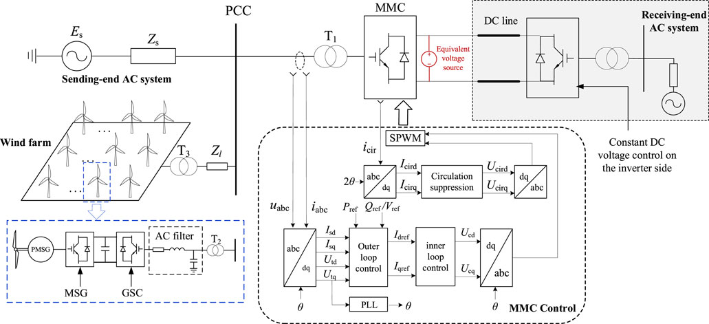
Figure 1 depicts the MMC-HVDC system with integration of a wind farm. The sending-end AC system comprises of a wind farm and an equivalent AC power grid. The type of wind turbine in the wind farm is permanent magnet synchronous generator (PMSG). The machine-side converter (MSC) and grid-side converter (GSC) control the active power and internal DC voltage, respectively. The wind farm is connected to PCC by step-up transformer T3 and AC line impedance Zl. The equivalent AC system is represented by a voltage source Es behind an impedance Zs with respect to the PCC.
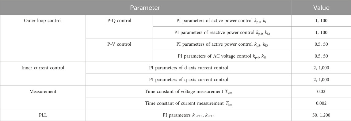
The rectifier MMC station is connected to sending-end AC system by converter transformer T1. The inverter MMC station adopts constant DC voltage control so that the DC voltage of the MMC-HVDC system can remain basically unchanged in steady state. Thus, the inverter side is simplified as a constant DC voltage source. The main parameters of MMC-HVDC system are listed in Table 1. The control system of rectifier MMC station is also illustrated in Figure 1, which includes outer loop control (P-Q control or P-V control), inner current control, circulation current suppression control and PLL. The control parameters are listed in Table 2.
2.2 The state space model of MMC-HVDC system under different control strategies
2.2.1 P-Q control strategy
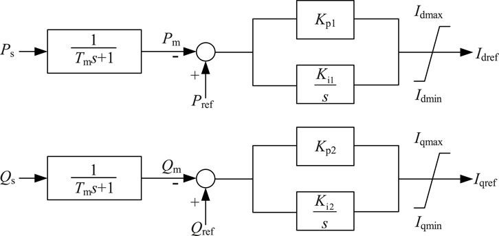
The P-Q control strategy ensures that the active and reactive power at PCC is constant. The control structure is shown in Figure 2. By comparing the given and measured active power and reactive power in the outer loop control, the d/q-axis current references Idref and Iqref are provided to the inner loop control, and a current saturation is added before the output current reference to avoid overcurrent in the case of system faults.
From Figure 2, the mathematical model of the outer loop control is given in Equation 1:
where Pref, Qref is the reference value of active and reactive power respectively; Pm, Qm is the measured active and reactive power respectively. kp1 and ki1 are the proportional and integral gains of active power control; kp2 and ki2 are the proportional and integral gains of reactive power control.
Introducing intermediate variables x1 and x2, let
2.2.2 P-V control strategy
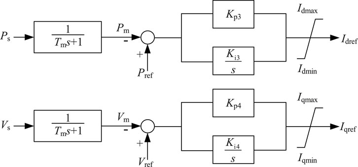
The P-V control strategy ensures that the active power and the AC voltage amplitude at PCC are constant. The control structure is similar to the P-Q control strategy, as shown in Figure 3.
From Figure 3, the mathematical model of the outer loop control is given in Equation 3:
where Pref, Pm is the reference and measured value of active power respectively; Vref, Vm is the reference and measured value of AC voltage respectively. kp3 and ki3 are the proportional and integral gains of active power control; kp4 and ki4 are the proportional and integral gains of AC voltage control.
Introducing intermediate variables x3 and x4, let
2.2.3 State space model
The whole wind farm is equivalent to one wind turbine (Wang et al., 2020) for simplification. The machine-side converter (MSC) and grid-side converter (GSC) control the active power and internal DC voltage, respectively. The modelling of PMSG can be referred to Shao et al. (2021) and can be expressed by Equation 5:
Where, XWT is the state vector, and UWT is the input vector of the wind turbine.
The state space model of MMC outer loop is introduced in the last section. The inner current control, circulation current control and PLL in the MMC station can be modeled by referring to Guo et al. (2023). Based on the above mathematical models of P-Q and P-V outer control, the state-space model of MMC-HVDC system with integration of wind farm can be established, as shown in Equation 6.
Where,
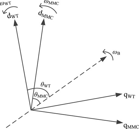
The control systems of PMSG and the MMC converter are based on different dq rotating reference frames, so it is necessary to establish the interface between the state space models of each subsystem. The relative positions of the dq rotational reference frames of PMSG and the MMC converter are shown in Figure 4.
The dashed line in Figure 4 represents the synchronous rotation axis, and the rotation frequency is the rated angular frequency ωB. The frequency and phase angle from PLL of PMSG and MMC converter are represented by ωWT, θWT, ωMMC, θMMC respectively, and the conversion between the two reference frames are shown in Equation 7.
With the model of PMSG, MMC converter and the interface between two reference frames, the state-space model of MMC-HVDC system with integration of wind farm can be established, as shown in Equation 8.
By linearizing the above state space equations, the small signal models of MMC-HVDC system under different control strategies are obtained, as shown in Equation 9.
Where, X is the state vector, A is the state matrix, B is the input matrix, and U is the input vector.
2.3 Small signal stability analysis of MMC-HVDC system under different converter control strategies
To study the dynamic stability of the MMC-HVDC system under P-Q and P-V control strategies, this section evaluates the influence of the AC grid impedance and the renewable energy capacity on the system stability when MMC station adopts P-Q and P-V control respectively.
The initial wind farm capacity PWF is 400 MW (0.4p.u. with regards to MMC rated capacity), and the AC grid impedance Zs is 0.25p.u. The AC system strength can be reflected by the wind farm capacity PWF as well as AC grid impedance Zs. A larger PWF/Zs indicates a weaker AC system and vice versa. When the outer loop of MMC-HVDC converter station adopts P-Q control strategy, the eigenvalue loci of the system are obtained when the AC grid impedance Zs and the wind farm capacity PWF are changed respectively, as shown in Figure 5.
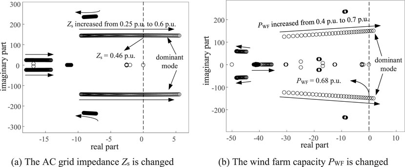
Figure 5. The eigenvalue loci of the system when adopting P-Q control strategy. (A) The AC grid impedance Zs is changed. (B) The wind farm capacity PWF is changed.
As can be seen from Figure 5, under P-Q control strategy, when the AC grid impedance Zs is increased from 0.25p.u. to 0.6p.u. or the wind farm capacity PWF is increased from 0.4p.u. to 0.7p.u., the dominant mode will pass through the imaginary axis and enter the right-half-plane (RHP), indicating system instability. The MMC-HVDC system enters an unstable condition when Zs > 0.46 p.u. or PWF > 0.68 p.u. under P-Q control mode, as depicted in Figure 5.
Similarly, when the outer loop of MMC-HVDC converter station adopts P-V control strategy, the eigenvalue loci of the system is observed when the AC grid impedance Zs and the wind farm capacity PWF are changed respectively, as shown in Figure 6.
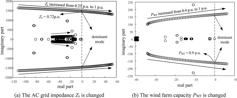
Figure 6. The eigenvalue loci of the system when adopting P-V control strategy. (A) The AC grid impedance Zs is changed. (B) The wind farm capacity PWF is changed.
As can be seen from Figure 6, under the P-V control strategy, when the AC grid impedance Zs is increased from 0.25p.u. to 1p.u. or the wind farm capacity PWF is increased from 0.4p.u. to 1p.u., the dominant mode will pass through the imaginary axis and enter the RHP, indicating system instability. The MMC-HVDC system enters an unstable condition when Zs > 0.72 p.u. or PWF > 0.9 p.u. under P-V control mode, as depicted in Figure 6.
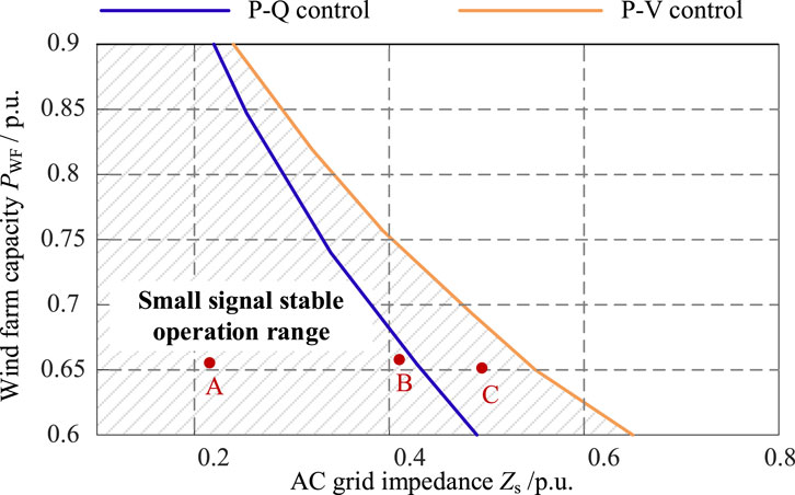
Based on the above analysis, the MMC-HVDC system has a wider stable operating range when adopting P-V control compared to P-Q control. To further support the conclusion, the maximum AC grid impedance to ensure stable operation under different wind farm capacity is shown in Table 3 and Figure 7.
As can be seen from Figure 7, under different wind farm capacity, the MMC-HVDC system with P-V control has a larger feasible range of AC grid impedance, indicating that the MMC-HVDC system with P-V control can operate stably under a weaker AC system compared to P-Q control. However, under P-V control strategy, the converter station will output a certain amount of reactive power, which will affect the steady-state operating point of the system. Therefore, when the operating condition of the MMC-HVDC system changes, a reasonable converter control strategy should be selected to make the system always operate in the optimal operating mode.
3 Flexible switching method of control strategy for MMC-HVDC converter
3.1 Flexible switching principle of control strategy
From the analysis in Section 2, different control strategies have different applicability to the operating conditions. In order to maintain the stable operation of the MMC-HVDC system, it is necessary to switch the converter control strategy according to the given operating conditions. Random switching of the control strategy may cause certain disturbance to the system, and in serious cases, may cause the system to enter a transient process and result in system instability. Thus, the flexible control switching method in this paper considers a clear match between the control strategy and the operating conditions.
On the other hand, the control switching will impose transient disturbance to the MMC-HVDC system and affect its power supply quality. Moreover, when the MMC-HVDC system is operated under weak grid conditions, the disturbance caused by control switching may further worsen the system stability. To achieve a smooth control switching, the flexible control switching method in this paper considers the switching of input measurement, intermediate variables and control output simultaneously, to ensure a smooth transition of operating point before and after the control switching.
3.2 Flexible switching method of control strategy
A flexible control switching method is proposed in this paper to ensure an undisturbed or smooth switching of control strategies for MMC-HVDC converter. The flexible control switching method adopts the pre-synchronous switching method, that is, when one control strategy is put into operation, the rest of the control strategies are in the “standby” mode. The output of the standby control strategy is adjusted by tracking the system operating point to achieve an undisturbed switching.
The outer loop control strategy under grid-connected condition includes the P-Q control strategy and P-V control strategy. From the control diagram, it can be found that these two control strategies have the same output in steady state, which is the d/q-axis current reference. Thus, the switching of the outer loop control only includes the switch of input measurement and reference value before the PI (proportional integral) controller. Since the active power control exists in both P-Q and P-V control strategies, the switch of active power control is not needed. Figure 8 shows the schematic diagram of the flexible switching method with pre-synchronization between the P-Q and P-V control.
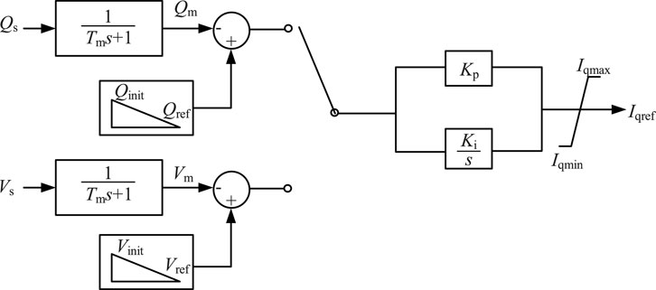
Figure 8. Schematic diagram of the flexible switching method with pre-synchronization between the P-Q and P-V control.
As shown in Figure 8, the two outer loop control strategies share the same PI controller. To switch from P-Q control to P-V control, the P-Q control is in operation and P-V control is in standby mode before the switching. The P-V control tracks the PCC voltage synchronously which is sent to the input reference as Vinit. In this way, when the control switching is activated, the error between the measured AC voltage and the reference value is zero, which ensures an undisturbed operating point after the switching. Then the P-V control smoothly changes the voltage reference to the given Vref. Same procedure for the control switching from P-V control to P-Q control. The P-Q control tracks the reactive power synchronously which is sent to the input reference as Qinit before the control switching. After the smooth control switching with unchanged operating point, the P-Q control smoothly changes the reactive power reference to the given Qref. With the proposed flexible control switching method, the MMC converter can realize a smooth control switching without imposing big disturbances to the system.
From the analysis in last section, the MMC-HVDC system with P-V control has a larger stable operation range compared to P-Q control, indicating that the MMC-HVDC system with P-V control can operate stably under a weaker AC system. However, when adopting P-V control strategy, the converter station needs to provide or absorb certain amount of reactive power, which will limit the transmission capacity of active power. The P-Q control strategy usually controls the reactive power to 0 to maximize the active power transmission when the converter capacity is limited. To ensure the maximum transmission of active power from renewable energy, the MMC converter station should adopt P-Q control if there is enough system stability margin. When the AC grid gets weaker with a reduced stability margin, the MMC converter can switch to P-V control to ensure a stable operation.
4 Verification of flexible switching of converter control strategy
Based on the MMC-HVDC system established in Section II, a simulation model is built on the PSCAD/EMTDC platform to verify the feasibility and effectiveness of the flexible control switching method for MMC-HVDC converter.
4.1 Case I: Verification of smooth switching of converter control strategy
At initial state, the MMC-HVDC system operates at rated operating point. The flexible control switching is applied at t = 8s and the time-domain simulation results before and after the control switching is shown in Figure 9. Figure 9A–C shows the simulation results when the converter control switches from P-Q control to P-V control, and Figure 9B–D shows the simulation results when the converter control switches from P-V control to P-Q control.
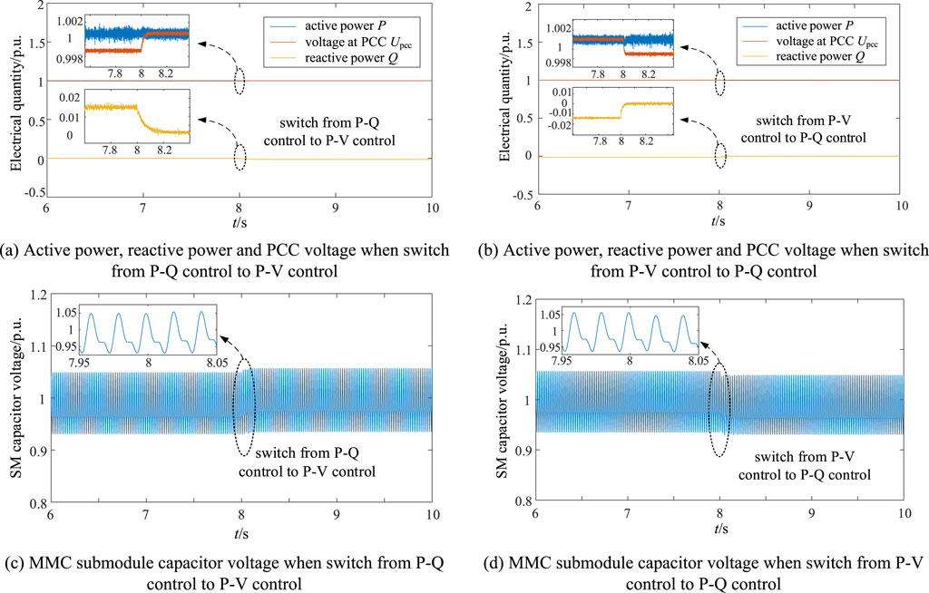
Figure 9. Time-domain simulation results during flexible switching of converter control strategy. (A) Active power, reactive power and PCC voltage when switch from P-Q control to P-V control. (B) Active power, reactive power and PCC voltage when switch from P-V control to P-Q control. (C) MMC submodule capacitor voltage when switch from P-Q control to P-V control. (D) MMC submodule capacitor voltage when switch from P-V control to P-Q control.
As shown in Figure 9, very small disturbance is observed during the switching between P-Q control and P-V control, proving the feasibility of the flexible control switching method for MMC converter.
4.2 Case II: Verification of the effectiveness of flexible control switching strategy to maintain stable operation
At initial state, the MMC-HVDC system operates at operating point A with adequate system stability margin, as shown in Figure 7. The initial control strategy of MMC converter is P-Q control strategy. The system operating point is changed from A to B at t = 4s and from B to C at t = 6s. The system operating points A, B, C are shown in Figure 7. Comparing the system behavior of MMC-HVDC with or without flexible control switching strategy, Figures 10A, B show the simulation results when the system operating point changes.
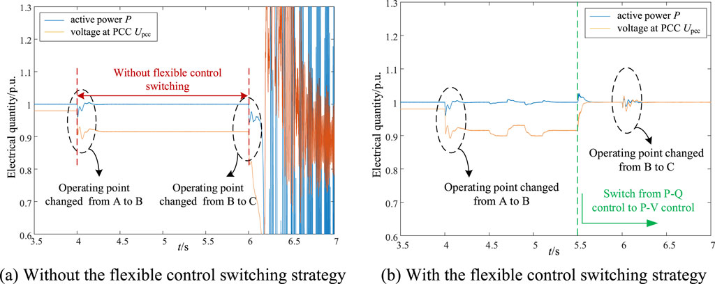
Figure 10. Simulation results of the MMC-HVDC system after operating condition changes. (A) Without the flexible control switching strategy. (B) With the flexible control switching strategy.
As seen from Figure 10, when the operating point is changed from A to B, the MMC-HVDC system can remain stable operation with P-Q control. However, when the operating point is changed from B to C, the MMC-HVDC system with P-Q control will experience system instability. The MMC-HVDC system with flexible control switching strategy will switch from P-Q control to P-V control to ensure a stable operation when the AC system gets weaker. Case II proves the effectiveness of flexible control switching strategy to maintain the stable operation of the MMC-HVDC system under changing operating conditions.
5 Conclusion
A single control strategy is difficult to apply to different operating conditions. To evaluate the dynamic stability and control applicability of different converter control strategies, the state space model of MMC-HVDC system with integration of wind farm under different control strategies is established, and the small signal stability and stable operation range under different control strategies are analyzed. Then, a flexible switching method of the control strategy for MMC-HVDC converter is proposed. The conclusions are as follows.
(1) Based on the stability analysis of MMC-HVDC system, the system stability margin will decrease when the AC grid impedance or the wind farm capacity is increased. The MMC-HVDC system with P-V control has a larger stable operation range compared to P-Q control, indicating that the MMC-HVDC system with P-V control can operate stably under a weaker AC system.
(2) A flexible control switching method for MMC-HVDC converter is proposed using a pre-synchronous method. With the proposed flexible control switching method, the MMC converter can realize a smooth control switching without imposing big disturbances to the overall system. The simulation results show that very small disturbance is observed during the control switching and the flexible control switching strategy can effectively maintain the stable operation of the MMC-HVDC system under different operating conditions.
Data availability statement
The original contributions presented in the study are included in the article/supplementary material, further inquiries can be directed to the corresponding author.
Author contributions
MP: Writing–original draft. LF: Writing–review and editing. XH: Writing–original draft. MS: Writing–original draft. WJ: Writing–review and editing. CG: Writing–review and editing.
Funding
The author(s) declare that financial support was received for the research, authorship, and/or publication of this article. This work is supported by the Science and Technology Project of China Southern Power Grid EHV Power Transmission Company, China Southern Power Grid Joint Laboratory of DC transmission Equipment and Submarine Cable Safety Operation (Research on Identification of Short Circuit Capacity and Stability Control Technology of HVDC System, No. 0120002023030301SJ00078).
Conflict of interest
Authors MP and LF were employed by CSG EHV Power Transmission Company.
The authors declare that this study received funding from the Science and Technology Project of China Southern Power Grid EHV Power Transmission Company. The funder had the following involvement in the study: study design, analysis and writing of this article.
Publisher’s note
All claims expressed in this article are solely those of the authors and do not necessarily represent those of their affiliated organizations, or those of the publisher, the editors and the reviewers. Any product that may be evaluated in this article, or claim that may be made by its manufacturer, is not guaranteed or endorsed by the publisher.
Abbreviations
MMC-HVDC, Modular multilevel converter based high voltage direct current; RES, Renewable Energy Source; P-Q control, Active power and reactive power control; P-V control, Active power and AC voltage control; VCC, Vector Current Control; PLL, Phase Locked Loop; PCC, Point of Common Coupling; VSI, Voltage Source Inverter; VSG, Virtual Synchronous Generator; PMSG, Permanent Magnet Synchronous Generator; MSC, Machine-side Converter; GSC, Grid-side Converter.
References
Ahmed, N., Haider, A., Van Hertem, D., Zhang, L., and Nee, H.-P. (2011). “Prospects and challenges of future HVDC SuperGrids with modular multilevel converters,” in EPE 14th European conference on power electronics and applications, 1–10.
Barsali, S., Ceraolo, M., Pelacchi, P., and Poli, D. (2002). “Control techniques of Dispersed Generators to improve the continuity of electricity supply,” in IEEE power engineering society winter meeting. Conference proceedings (cat. No.02CH37309).
Du, W., Bi, J., Cao, J., and Wang, H. F. (2015). A method to examine the impact of grid connection of the DFIGs on power system electromechanical oscillation modes. IEEE Trans. Power Syst. 31 (5), 3775–3784. doi:10.1109/tpwrs.2015.2494082
Egea-Alvarez, A., Fekriasl, S., Hassan, F., and Gomis-Bellmunt, O. (2015). Advanced vector control for voltage source converters connected to weak grids. IEEE Trans. Power Syst. 30 (6), 3072–3081. doi:10.1109/tpwrs.2014.2384596
Guo, C., Xu, L., Yang, S., and Jiang, W. (2023). A supplementary damping control for MMC-HVDC system to mitigate the low-frequency oscillation under low inertia condition. IEEE Trans. Power Deliv. 38 (1), 287–298. doi:10.1109/TPWRD.2022.3186940
Hao, X., Guo, C., Jiang, W., Peng, M., and Lin, X. (2022). Identification method for equivalent impedance of AC power grid connected to MMC-HVDC system based on reactive power injection. Automation Electr. Power Syst. 47 (9), 184–192.
Hu, J., Huang, Y., Wang, D., Yuan, H., and Yuan, X. (2015). Modeling of grid-connected DFIG-based wind turbines for DC-link voltage stability analysis. IEEE Trans. Sustain. Energy 6 (4), 1325–1336. doi:10.1109/tste.2015.2432062
Jenny, Z. Z., and Gole, A. M. (2012). “VSC transmission limitations imposed by AC system strength and AC impedance characteristics,” in 10th IET international conference on AC and DC power transmission (ACDC 2012).
Katiraei, F., and Iravani, M. R. (2006). Power management strategies for a microgrid with multiple distributed generation units. IEEE Trans. Power Syst. 21 (4), 1821–1831. doi:10.1109/tpwrs.2006.879260
Li, Y., Su, J., Xu, H., and Shi, Y. (2019). VSG/PQ control of grid-connected inverter and smooth switching method. Power Electron. 53 (7), 111–114.
Ling, X., and Fan, L. (2013). Impedance-based resonance analysis in a VSC-HVDC system. IEEE Trans. Power Deliv. 28 (4), 2209–2216. doi:10.1109/tpwrd.2013.2272382
Peng, F. Z. (2003). Z-source inverter. IEEE Trans. Industry Appl. 39 (2), 504–510. doi:10.1109/tia.2003.808920
Shao, B., Zhao, S., Yang, Y., Gao, B., and Blaabjerg, F. (2021). Sub-synchronous oscillation characteristics and analysis of direct-drive wind farms with VSC-HVDC systems. IEEE Trans. Sustain. Energy 12 (2), 1127–1140. doi:10.1109/tste.2020.3035203
Shi, R., Zhang, X., Xu, H., Liu, F., Hu, C., and Yu, Y. (2016). Seamless switching control strategy for microgrid operation modes based on virtual synchronous generator. Automation Electr. Power Syst. 40 (10), 16–23.
Vasquez, J. C., Guerrero, J. M., Gregorio, E., Rodriguez, P., Teodorescu, R., and Blaabjerg, F. (2008). “Adaptive droop control applied to distributed generation inverters connected to the grid,” in 2008 IEEE international symposium on industrial electronics.
Vasquez, J. C., Guerrero, J. M., Luna, A., Rodriguez, P., and Teodorescu, R. (2009). Adaptive droop control applied to voltage-source inverters operating in grid-connected and islanded modes. IEEE Trans. Industrial Electron. 56 (10), 4088–4096. doi:10.1109/tie.2009.2027921
Wang, C., Li, X., Guo, L., and Li, Y. (2012). A seamless operation mode transition control strategy for a microgrid based on master-slave control. Sci. China Technol. Sci. 55 (6), 1644–1654. doi:10.1007/s11431-012-4811-z
Wang, D., Hu, J., Huang, Y., Wang, N., and Zhou, Q. (2014). “Stability of DC-link voltage affected by phase-locked loop for DFIG-based wind turbine connected to a weak AC system,” in 2014 17th international conference on electrical machines and systems (ICEMS).
Wang, P., Zhang, Z., Huang, Q., and Lee, W. J. (2020). Wind farm dynamic equivalent modeling method for power system probabilistic stability assessment. IEEE Trans. Industry Appl. 56 (3), 2273–2280. doi:10.1109/tia.2020.2970377
Keywords: modular multilevel converter (MMC), renewable energy sources, small signal stability, flexible control switching, P-Q control strategy, P-V control strategy
Citation: Peng M, Feng L, Hao X, Sun M, Jiang W and Guo C (2025) Flexible switching method of control strategy for MMC-HVDC converter based on AC power grid strength. Front. Electron. 5:1475338. doi: 10.3389/felec.2024.1475338
Received: 03 August 2024; Accepted: 13 December 2024;
Published: 08 January 2025.
Edited by:
Wenjie Liu, Northwestern Polytechnical University, ChinaReviewed by:
Yichao Sun, Nanjing Normal University, ChinaSmail Semaoui, Renewable Energy Development Center, Algeria
Chi Li, Tsinghua University, China
Lujie Yu, Tianjin University, China
Copyright © 2025 Peng, Feng, Hao, Sun, Jiang and Guo. This is an open-access article distributed under the terms of the Creative Commons Attribution License (CC BY). The use, distribution or reproduction in other forums is permitted, provided the original author(s) and the copyright owner(s) are credited and that the original publication in this journal is cited, in accordance with accepted academic practice. No use, distribution or reproduction is permitted which does not comply with these terms.
*Correspondence: Maolan Peng, cG1sMTA4MTE3MDkxMkAxNjMuY29t
 Maolan Peng1*
 Wen Jiang