 Khalid Alammari1
 Majid Ahmadi
 Arash Ahmadi
- 1Department of Electrical and Computer Engineering, University of Windsor, Windsor, ON, Canada
- 2Department of Electronics, Carleton University, Ottawa, ON, Canada
This study introduces a pioneering design for leaky integrate-and-fire (LIF) neurons by integrating memristor devices with CMOS transistors, thereby forming an innovative hybrid CMOS/memristor neuron circuit. Employing Pt/TaOx/Ta as the memristor device, the proposed model was meticulously implemented and rigorously evaluated using the Cadence Virtuoso simulation environment. The simulation outcomes affirm the effective functionality of the design, marking a significant advancement in hybrid circuit engineering. Notably, the proposed neuron circuit exhibits a compact footprint, attributed to the efficient utilization of hybrid CMOS/memristor gates. This characteristic is poised to address the critical challenge of scaling in current neuromorphic systems, offering a viable pathway to substantially augment density and cater to the escalating demands of advanced computational architectures. The findings of this research hold promising implications for enhancing the efficiency and scalability of neuromorphic systems, setting a new benchmark for future developments in this domain.
1 Introduction
Inspired by the human brain, neuromorphic systems have drawn much attention in recent years due to their massive parallelism, low power consumption, fault tolerance, and capacity for adaptive learning (Indiveri et al., 2006; Benjamin et al., 2014; Mead, 1990; Yu et al., 2011). In addition to conventional computing systems, von Neumann is facing severe challenges (Stefano et al., 2018), which made brain-inspired computing an alternative approach for conventional computing systems. Thus, hardware implementation for neuromorphic systems has been an ambitious research field and very appealing to computing architecture. The complementary metal oxide semiconductor (CMOS) technology offers the platform to realize the neuromorphic systems to emulate the computations inside the human brain, which is required for implementation of neuron circuits and electronic synapses. Therefore, several works have been proposed on many neuron circuits, such as integrate-and-fire (I&F) neurons (Brink et al., 2012), leaky integrate-and-fire (LIF) neurons (Sangya et al., 2017), and electronic synapses (Seo et al., 2011). Although these CMOS-based circuits have shown maturity toward emulating and understanding the neuromorphic systems, it comes at the price of occupying a large silicon area with considerable power consumption due to the high number of transistors involved. With the aim to solve this problem, the new emerging nonvolatile memory (NVM) devices known as memristors could be a promising candidate for future computing architecture, owing to their nanoscale size and the ability to integrate with the existing CMOS technology. Moreover, memristors can behave similarly to the human brain in adjusting or changing their responses to stimulation patterns (Gotarredona et al., 2013), making them a perfect choice to imitate biological behavior. There has been intensive research (Stefano et al., 2016; Sangsu et al., 2013; Bipin et al., 2013) covering the area of neuromorphic systems engaging memristors, whereas memristor devices are used to implement synapses with a crossbar structure. However, it is very difficult to integrate the pure memristive crossbar structure with CMOS neurons due to the differences in their logical states. In this paper, an LIF neuron model has been implemented based on the hybrid CMOS/memristor, taking the advantage of the ability to integrate standard CMOS with memristor devices and the capability of fabricating memristor devices on top of the CMOS substrate, which can provide additional storage and fast computing. The rest of this paper is arranged as follows: Section 2 briefly introduces the memristor ratioed logic (MRL), which is exploited as a design method for the LIF neuron. Section 3 includes information about implementing hybrid CMOS/memristor LIF neurons. Section 4 presents and discusses simulation results and discussion on MRL-based LIF neurons. Finally, remarks and conclusions are presented in Section 5.
2 Memristive design method
The memristor is a new emerging resistive device that adds new capabilities to the CMOS technology, which can enhance the performance of neuromorphic architectures. The integrated platform of CMOS/memristors, also known as MRL (Kvatinsky et al., 2012), offers the ability to perform all logic gates utilizing memristors and stack them in between CMOS upper layers (Cho et al., 2015), which will allow faster computing and additional storage at a reasonable chip area for neuromorphic hardware implementation. MRL is CMOS-compatible. Hence, the logical state of this method is based on the output voltage level. Thus, low and high voltage represent logical states (“0” and “1”), respectively. MRL-based AND and OR gate implementation requires only two memristors, while NAND and NOR gates require a CMOS inverter to be connected to the output of AND and OR gates to facilitate the circuits with the interface and control operation (Zidan et al., 2018). Figure 1 displays MRL-based AND, NAND, OR, and NOR. In this work, the memristor model
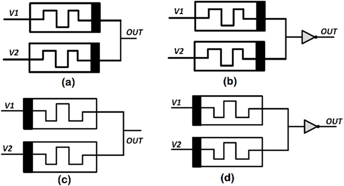
Figure 1. Schematic of MRL-based logic gates (A) AND, (B) NAND, (C) OR, and (D) NOR.
where Ldisc is the length of the disc zone in which switching activity takes place, N is oxygen vacancy in the disc zone, e is the elementary charge,
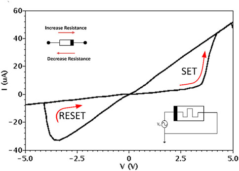
Figure 2. I–V curve of the
The device’s reliability and accuracy are impacted by Schottky current, which is responsible for changing the concentration of the oxygen vacancy. Schottky current has two components: the ionic current Iion and the current passing through the electronic resistance.
3 Hybrid CMOS/memristor LIF neuron
The LIF model is the most popular structure used to emulate the behavior of biological neurons. Figure 3 depicts the simplest form of the LIF model as a parallel combination of a capacitor Cmem as the membrane capacitor and the leaky resistor RLeak as the leak path resistance of the neuron with a voltage-controlled switch connected in parallel with the capacitor. The performance of the model shown in Figure 3 can be explained as follows: the input excitation current Iinput charges the membrane capacitor to produce a potential Vmem (integrating process); when the membrane potential Vmem exceeds a certain threshold Vth, the neuron fires, and a spike is generated (firing process); at the same time, the voltage-controlled switch is closed instantly to reset the membrane potential to a predefined resting potential value lower than the threshold value (resetting process). Equations 3, 4 describe the LIF model’s basic mechanism, which indicates that excitation and leakage currents control the membrane potential and vice versa.
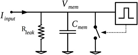
Figure 3. Schematic diagram of the leaky integrate-and-fire model.
A proposal for a memristive LIF neuron model has been presented in Figure 4 based on the MRL method. The design involves several building blocks as follows.
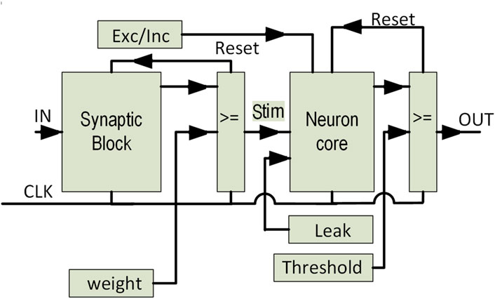
Figure 4. Schematic of the proposed MRL-based LIF neuron.
3.1 Synapse block
The synaptic weight is realized in this block based on the output pulse duration, which is generated when the input spikes trigger the block. Hence, the operations are implemented assuming that multiple inputs can be combined and applied to the counter’s input using MRL-based OR gate, assuming input spikes will not happen exactly at the same time (Heidarpur et al., 2024). The 4-bit memristor-based counter is the main element in this block. The up-counter has been implemented using the MRL-based up–down counter (Alammari et al., 2020). The MRL-based counter can change its count direction, whether up or down, at any point within the counting sequence. Hence, up-counting is chosen from the control mode (Alammari et al., 2020). The counter starts counting from the initial value until it reaches the synaptic weight, which is defined by the pulse width. Synaptic weights with larger values have wider pulses, thus having more effect on the neuron core. Synaptic weights are sent to the neuron core block. At the same time, a feedback signal is sent to reset the counter.
3.2 Neuron core
The integration and leak function are performed in this block. The integration process commences when a pulse is received from the synapse block. The membrane potential is realized by a 4-bit memristor-based up–down counter, which was implemented and tested in the Cadence Virtuoso schematic level and previously published in Alammari et al. (2020). The counter updates its logical states every time it receives a synaptic pulse. The counter is incremented or decremented based on the pulse type received from the synapse block. The parameter Exc/Inh indicates the type of the input spike, whether excitatory or inhibitory. However, when no synapse pulse is applied to the neuron core, the leak function takes place by continuously decrementing the counter.
3.3 Neuron output
The final stage in the design is to compare the output of the up–down counter “membrane potential” with a threshold value via a 4-bit memristor-based comparator. A spike is generated when the membrane potential exceeds the threshold value. Simultaneously, a feedback signal is sent to the neuron core to reset the membrane potential to its initial value.
4 Experimental results
The model for LIF neurons has been implemented based on the MRL method. Hence, the memristor devices are employed in the structure depicted in Figure 4. The LIF neuron is made up of a few simple blocks: counters, comparators, and logical gates. The main element in the design is the memristive counter, which was implemented and tested in the Cadence Virtuoso schematic level and previously published in Alammari et al. (2020). The mechanism of the LIF neural model can be explained as follows: the up–down counter begins counting as the input “Stim” generated from the synapse block entering the counter. The counter starts the up-counting when the parameter Exc/Inh is at logic 1. Otherwise, down-counting is performed. The width of the pulse, which is received from the synapse block, provides information about the synaptic weights. However, when no synapse pulse is applied to the neuron core, the counter has no counting activity and the counter’s value starts to decrease, emulating the leak behavior observed in the neuron model definition. Finally, a comparator is used to detect the threshold level. Figure 5 demonstrates the behavior of the memristive LIF model in Cadence Virtuoso. In the first period, the synaptic weights are accumulated, which contributes to the membrane potential until the threshold value (Vth = 7) is reached when the neuron fires. In the second period of the simulation, the membrane potential starts to decrease its value since there are no input spikes to the up–down counter “stim = 0,” and “the leak behavior.” Figure 6 confirms the action potential of the LIF neuron model. The exceptional features about this proposed memristive LIF neuron circuit compared to other works utilizing memristors (Myonglae et al., 2015; Yuning et al., 2018) is the comprehensive involvement of the memristor devices in every aspect of the design. In Myonglae et al. (2015) the LIF neuron is implemented using an integrator, comparator with eight switches, and control logic, while in Yuning et al. (2018), the neuron circuit comprises an analog demultiplexer, summing amplifier, and comparator, and the digital part includes AND and OR gates with D flip-flop (DFF). However, both designs have employed memristor devices only to implement synapses. At the same time, our study design shows that both memristive counters in the synapse block and the neuron core block employ four MRL-based T flip-flops (TFF) connected with other MRL-based Boolean gates shown in Figure 1. The circuit of MRL-based TFF consists of MRL-based DFF and MRL-based 2-input XOR gate. The DFF is an edge-triggered circuit consisting of two D-latches connected in series with a master–slave configuration to prevent any possibility of invalid input states. The hybrid memristor-CMOS logic gates AND, OR, and NOR are utilized and connected based on the schematic shown in Figure 7. The DFF involves 16 memristors and 14 MOSFETs, while the XOR gate requires six memristors and two MOSFETs. Hence, the memristive TFF shown in Figure 8 consists of 22 memristor devices and 16 MOSFETs (Alammari et al., 2020). The four memristive TFFs can produce a 4-bit representing the counting sequence once TFFs are trigged. The MRL-based counter in each block of the memristive neuron circuit can change its count direction, whether up or down, at any point within the counting sequence. The TFF is an essential element in the design since it assesses both counters regarding the area, delay, and power consumption. Table.1 presents a comparison of the memristive TFF against other CMOS-based TFF (Abiri et al., 2014). The memristive comparator was implemented based on the memristor-based MRL logic gates depicted in Figure 9. The number of all devices which contribute to the circuit of the memristive neuron is listed in Table 2, which indicates that the MRL-based design is efficient in terms of the layout area. It can be seen from Table 2 that in the hybrid memristor-CMOS-based up–down counter, the number of transistors required is fewer than the number in traditional CMOS-based up–down counter with 110 memristors and 34 MOSFETs, which is less than half of the devices reported in Alioto et al. (2006); Abdel-Hafeez and Gordon-Ross (2011); Zhang and Hu (2012). The integral platform of CMOS transistors and memristor devices has led to almost 50% in area saving (Kvatinsky et al., 2012) compared to the same CMOS-based design. This is because of the limited utilized number of CMOS transistors in the proposed LIF neuron model as memristor devices can be fabricated on the upper layers of CMOS transistors (Cong and Xiao, 2011; Ru et al., 2011).
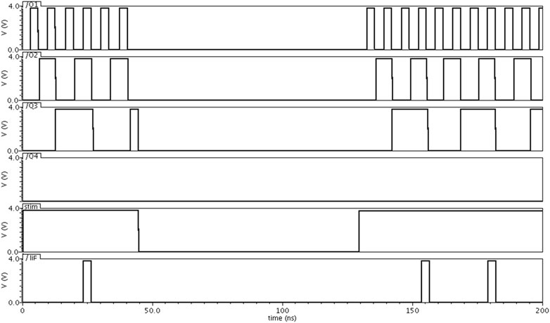
Figure 5. Time diagrams for the proposed MRL-based LIF neuron. Output of the up–down counter Q1 Q2 Q3 Q4 begins incremented /decremented as the input “Stim” generated from the synapse block. Synaptic weights accumulated until the threshold value (Vth=7) is reached when the neuron fires.
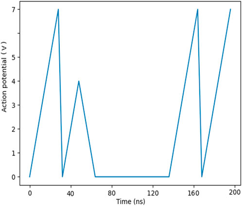
Figure 6. Action potential of the memristive LIF neuron model shows three fire events taking place as the threshold value (Vth=7) is reached and one short spike due to short current because of no input spikes to inter the up–down counter “leak behavior commences.”

Figure 7. Circuit schematic for T flip-flops (TFF).
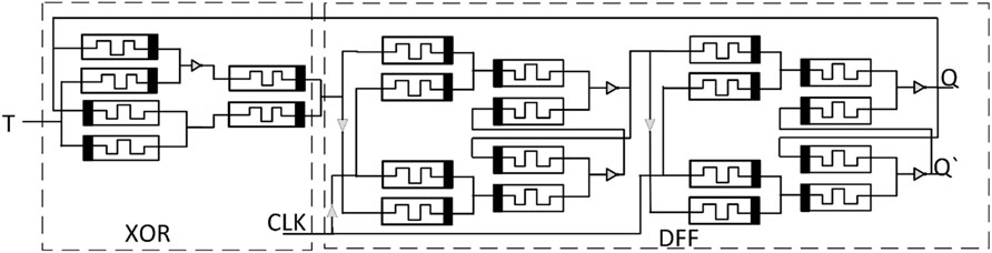
Figure 8. Circuit schematic of the memristor-based TFF.
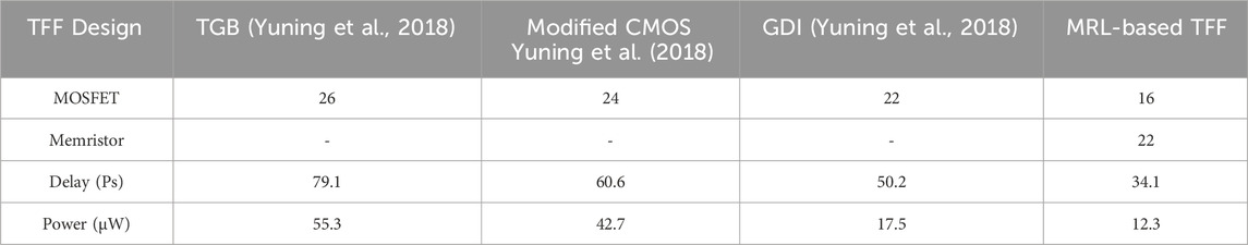
Table 1. A comparison between the number of CMOS-based TFF and the proposed memristive TFF.
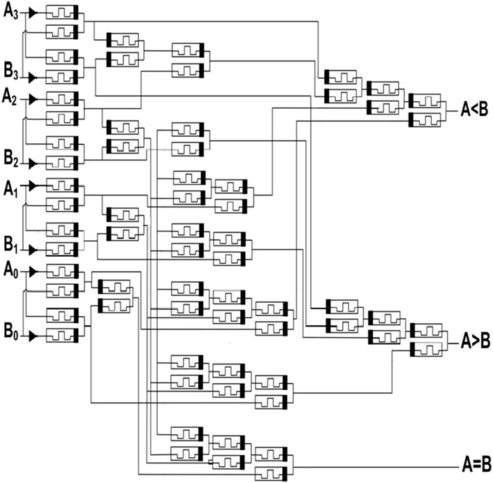
Figure 9. Circuit schematic of the memristor-based 4-bit comparator.

Table 2. Number of all devices in the proposed design of the memristive LIF neuron.
5 Conclusion
This work utilizes the
Data availability statement
The original contributions presented in the study are included in the article/Supplementary Materials; further inquiries can be directed to the corresponding author.
Author contributions
KA: data curation, formal analysis, funding acquisition, investigation, methodology, software, validation, writing–original draft, and writing–review and editing. MH: Writing–review and editing, Data curation, Validation, Software. MA: conceptualization, formal analysis, investigation, methodology, project administration, supervision, validation, and writing–review and editing. AA: conceptualization, investigation, supervision, writing–review and editing, methodology, and resources.
Funding
The author(s) declare that no financial support was received for the research, authorship, and/or publication of this article.
Conflict of interest
The authors declare that the research was conducted in the absence of any commercial or financial relationships that could be construed as a potential conflict of interest.
Publisher’s note
All claims expressed in this article are solely those of the authors and do not necessarily represent those of their affiliated organizations, or those of the publisher, the editors, and the reviewers. Any product that may be evaluated in this article, or claim that may be made by its manufacturer, is not guaranteed or endorsed by the publisher.
Supplementary material
The Supplementary Material for this article can be found online at: https://www.frontiersin.org/articles/10.3389/felec.2024.1366299/full#supplementary-material
References
Abdel-Hafeez, S., and Gordon-Ross, A. (2011). A digital CMOS parallel counter architecture based on state look-ahead logic. IEEE Trans. Very Large-Scale Integration (VLSI) Syst. 19 (6), 1023–1033. doi:10.1109/tvlsi.2010.2044818
Abiri, E., Salehi, M. R., and Darabi, A. (2014). “Design and simulation of low-power and high-speed T-Flip Flop with the modified gate diffusion input (GDI) technique in nano process,” in 2014 22nd Iranian Conference on Electrical Engineering (ICEE), 20-22 May 2014, Tehran, 82–87.
Alammari, K., Ahmadi, A., and Ahmadi, M. (2020). “Hybrid memristor-CMOS based up-down counter design,” in 27th IEEE International Conference on Electronics, Circuits and Systems (ICECS), 23-25 Nov. 2020, China, 1–4.
Alioto, M., Mita, R., and Palumbo, G. (2006). Design of high-speed power-efficient MOS current-mode logic frequency dividers. IEEE Trans. Circuits Syst. II Express Briefs 53 (11), 1165–1169. doi:10.1109/tcsii.2006.882350
Benjamin, B. V., Gao, P., McQuinn, E., Choudhary, S., Chandrasekaran, A. R., Bussat, J. M., et al. (2014). Neuro grid: a mixed-analog-digital multichip system for large-scale neural simulations. Proc. IEEE 102 (5), 699–716. doi:10.1109/jproc.2014.2313565
Bipin, R., Liu, Y., Seo, J., Gopalakrishnan, K., Chang, L., Friedman, D., et al. (2013). Specifications of nanoscale devices and circuits for neuromorphic computational systems. IEEE Trans. Electron Devices 60 (1), 246–253. doi:10.1109/ted.2012.2227969
Brink, S., Nease, S., Hasler, P., Ramakrishnan, S., Wunderlich, R., Basu, A., et al. (2012). A learning-enabled neuron array IC based upon transistor channel models of biological phenomena. IEEE Trans. Biomed. Circuits Syst. 7 (1), 71–81. doi:10.1109/tbcas.2012.2197858
Chen, P., and Yu, S. (2015). Compact modeling of RRAM devices and its applications in 1t1r and 1s1r array design. IEEE Trans. Electron Devices 62 (12), 4022–4028. doi:10.1109/ted.2015.2492421
Cho, K., Lee, S., and Eshraghian, K. (2015). Memristor-CMOS-logic-and-digital computational components. Microelectron. J. 46 (3), 214–220. doi:10.1016/j.mejo.2014.12.006
Cong, J., and Xiao, B. (2011). “MRFPGA: a novel FPGA architecture with memristor-based reconfiguration,” in IEEE/ACM International Symposium on Nanoscale Architectures, China, 8-10 Nov. 2021, 1–8.
Gotarredona, S., Masquelier, T., Prodromakis, T., Indiveri, T., and Linares-Barranco, B, G. (2013). STDP and STDP variations with memristors for spiking neuromorphic learning systems. Front. Neurosci. 7, 2. doi:10.3389/fnins.2013.00002
Heidarpur, M., Ahmadi, A., and Ahmadi, M. (2024). The silence of the neurons: an application to enhance performance and energy efficiency. Front. Neurosci. 17, 1333238. doi:10.3389/fnins.2023.1333238
Indiveri, G., Chicca, E., and Douglas, R. (2006). A VLSI array of low-power spiking neurons and bistable synapses with spike-timing dependent plasticity. IEEE Trans. Neural Netw. 17 (1), 211–221. doi:10.1109/tnn.2005.860850
Kvatinsky, S., Ramadan, M., Friedman, E. G., and Kolodny, A. (2015). VTEAM: a general model for voltage-controlled memristors. IEEE Trans. Circuits Syst. II Express Briefs 62 (8), 786–790. doi:10.1109/tcsii.2015.2433536
Kvatinsky, S., Wald, N., Satat, G., Kolodny, A., Weiser, U. C., and Friedman, E. G. (2012). “MRL-memristor ratioed logic,” in 13th international workshop on cellular nanoscale networks and their applications. Turin, Italy: IEEE, 1–6.
Mead, C. (1990). Neuromorphic electronic systems. Proc. IEEE 78 (10), 1629–1636. doi:10.1109/5.58356
Myonglae, C., Kim, B., Park, S., Hwang, H., Jeon, M., Lee, B., et al. (2015). Neuromorphic hardware system for visual pattern recognition with memristor array and CMOS neuron. IEEE Trans. Industrial Electron. 62 (4), 2410–2419. doi:10.1109/tie.2014.2356439
Ru, H., Zhang, L., Gao, D., Pan, Y., Qin, S., Tang, P., et al. (2011). Resistive switching of silicon-rich-oxide featuring high compatibility with CMOS technology for 3D stackable and embedded applications. Appl. Phys. A 102, 927–931. doi:10.1007/s00339-011-6310-7
Sangsu, P., Noh, J., Choo, M., Sheri, A., Chang, M., Kim, Y., et al. (2013). Nanoscale RRAM-based-synaptic-electronics-toward-a-neuromorphic-computing-device. Nano Tec. no " Nanotechnol. 24 (38), 1–6. doi:10.1088/0957-4484/24/38/384009
Sangya, D., Kumar, V., Shukla, A., Mohapatra, N., and Ganguly, U. (2017). Leaky integrate and fire neuron by charge-discharge dynamics in floating-body MOSFET. Sci. Rep. 7 (1), 8257. doi:10.1038/s41598-017-07418-y
Seo, J.-sun, Brezzo, B., Liu, Y., Parker, B., Esser, S., Montoye, R., et al. (2011). “A 45nm CMOS neuromorphic chip with a scalable architecture for learning in networks of spiking neurons,” in 2011 IEEE Custom Integrated Circuits Conference (CICC), 19-21 Sept. 2011, China, 1–4.
Siemon, A., Menzel, S., Marchewka, A., Nishi, Y., Waser, R., and Linn, E. (2014). “Simulation of TaOx-based complementary resistive switches by a physics-based memristive model,” in IEEE International Symposium on Circuits and Systems (ISCAS), 1420–1423.
Stefano, A., Balatti, S., Milo, V., Carboni, R., Wang, Z., Calderoni, A., et al. (2016). Neuromorphic learning and recognition with one-transistor-one-resistor synapses and bistable metal oxide RRAM. IEEE Trans. Electron Devices 63 (4), 1508–1515. doi:10.1109/ted.2016.2526647
Stefano, A., Narayanan, P., Tsai, H., Shelby, R., Boybat, I., Nolfo, C., et al. (2018). Equivalent-accuracy accelerated neural-network training using analogue memory. Nature 558, 60–67. doi:10.1038/s41586-018-0180-5
Yu, S., Wu, Y., Jeyasingh, R., Kuzum, D., and Wong, H.-P. (2011). An electronic synapse device based on metal oxide resistive switching memory for neuromorphic computation. IEEE Trans. Electron Devices 58 (8), 2729–2737. doi:10.1109/ted.2011.2147791
Yuning, J., Huang, P., Zhu, D., Zhou, Z., Han, R., Liu, L., et al. (2018). Design and hardware implementation of neuromorphic systems with RRAM synapses and threshold-controlled neurons for pattern recognition. IEEE Trans. Circuits Syst. I Regul. Pap. 65 (9), 2726–2738. doi:10.1109/tcsi.2018.2812419
Zhang, T., and Hu, Q. (2012). “A high-speed and low power up/down counter in CMOS technology,” in 2012 International Conference on Wireless Communications and Signal Processing (WCSP), Huangshan, 1–3.
Keywords: memristor, memristor ratioed logic, complementary metal oxide semiconductor technology, up–down counter, logic gates, leaky integrate-and-fire neuron
Citation: Alammari K, Heidarpur M, Ahmadi M and Ahmadi A (2024) LIF neuron —a memristive realization. Front. Electron. 5:1366299. doi: 10.3389/felec.2024.1366299
Received: 06 January 2024; Accepted: 13 August 2024;
Published: 06 September 2024.
Edited by:
Angela Slavova, Bulgarian Academy of Sciences (BAS), BulgariaReviewed by:
Valeri Mladenov, Eindhoven University of Technology, NetherlandsKapil Bhardwaj, National Institute of Technology, India
Copyright © 2024 Alammari, Heidarpur, Ahmadi and Ahmadi. This is an open-access article distributed under the terms of the Creative Commons Attribution License (CC BY). The use, distribution or reproduction in other forums is permitted, provided the original author(s) and the copyright owner(s) are credited and that the original publication in this journal is cited, in accordance with accepted academic practice. No use, distribution or reproduction is permitted which does not comply with these terms.
*Correspondence: Majid Ahmadi, YWhtYWRpQHV3aW5kc29yLmNh