 Amin Jalilian
 Duane A. Robinson
95% of researchers rate our articles as excellent or good
Learn more about the work of our research integrity team to safeguard the quality of each article we publish.
Find out more
REVIEW article
Front. Electron. , 10 August 2023
Sec. Power Electronics
Volume 4 - 2023 | https://doi.org/10.3389/felec.2023.1144383
The power swing characteristic of transmission lines (TLs) can be affected by the large-scale integration of inverter-based resources (IBRs), resulting in the maloperation of the legacy power swing blocking (PSB) and out-of-step tripping (OST) functions. This paper presents a brief review of power swing phenomena and the impact on power swing protection functions. In this regard, the impact of IBR integration of type-III, and type-IV wind turbine generation (WTG) on legacy power swing protection functions has been scrutinized. To do so, the performance of impedance-based PSB and OST functions during the IBR integration has been investigated via comprehensive simulation studies. The results show that under a system contingency and high IBR penetration, depending on the IBR technology, the system experiences frequency oscillations and swinging impedance trajectories which are different from those from synchronous generators, such that the reliable operation of the legacy PSB and OST functions can be jeopardized. Moreover, during power swing phenomena, the simulation results have found that the security of distance protection cannot be guaranteed and the fault ride-through requirements cannot be maintained when a high share of IBRs have been integrated.
The fault response of the inverter-based resources (IBRs) exhibits different transient and dynamic characteristics from those of conventional synchronous generators (SGs), which can lead to operational challenges to the reliable and secure operation of conventional protection functions of transmission lines (TLs). Following a large disturbance in power systems, such as a generator disconnection, a line switching and/or a loss of connection of a block of load, a temporary variation in the current and voltage can lead to a swinging phenomenon known as power swing condition (Paudyal et al., 2010). The power swing can be stable if the system reaches a new equilibrium point based on the defined operating boundaries, or it can be unstable if the system cannot retain its synchronism with the rest of the grid (Zhang and Zhang, 2018). The protection functions which measure the voltage and current signals may interpret the power swing condition as a fault situation and mistakenly trip the protected equipment (Hashemi and Sanaye-Pasand, 2019a). In the case of distance protection, which constitutes the backbone of protection of TLs, the variation of the current and voltage signals may cause the impedance trajectory to enter the operating zones of the distance relay and may cause an unintentional trip of healthy TLs (Hashemi and Sanaye-Pasand, 2018). This situation can further threaten system stability and can result in major widespread blackouts (Zare et al., 2018). For this purpose, the power swing protection functions, namely power swing blocking (PSB) and out-of-step tripping (OST), play a crucial role in ensuring a secure and reliable operation of power systems. In general, the main purpose of the power swing protection functions is to (Thakur et al., 2020):
1. Avoid the spurious trip of power system equipment during a stable power swing to allow the system to reach a new stable equilibrium point; and
2. Protect the power system during an unstable power swing to implement system protection schemes through controlled islanding in predefined locations to prevent system widespread blackouts and equipment damage.
These objectives are realized through the PSB and OST functions. To prevent the maloperation of the distance protection function during power swing, the PSB function measures the rate of change of impedance to distinguish the fault from the power swing and block the relay operation in case of a power swing condition (Sharifzadeh et al., 2014; Nayak et al., 2015). Likewise, to avoid widespread blackouts, the OST function distinguishes between the stable and the unstable power swing and initiates a trip signal for an unstable power swing to implement intentional islanding (Hashemi and Sanaye-Pasand, 2019b).
However, the fault response characteristics of the IBRs mainly depend on their converter control scheme and differ significantly from conventional SGs (Banaiemoqadam et al., 2020; Behnke et al., 2020; EPRI Technical Brief). Given these characteristics, the impacts of the IBRs on bulk power system protection functions including the power swing protection, directional relaying, negative sequence-based protection, etc., have been reported in (Haddadi et al., 2019; Haddadi et al., 2020; Jalilian and Muttaqi, 2020). In this regard, and as discussed in (Nagpal et al., 2020; Kou et al., 2020; Impact of IEEE), the performance of legacy power swing protection functions can be affected during IBR integration. This is because the reduced system inertia caused by the integration of IBRs can adversely affect the performance of the legacy PSB function such that it cannot distinguish a power swing from a fault situation, leading to the maloperation of the conventional PSB functions. Similarly, at high penetration levels of IBRs, the trajectory of swinging impedance can be affected to the extent that it can jeopardize the secure and reliable operation of the OST function (Paolone et al., 2020).
Accordingly, this paper presents a qualitative assessment of the performance of the power swing protection functions during type-III and type-IV wind turbine generation (WTG) integration through different case studies. In this regard, the possible maloperation of the power swing protection functions has been highlighted and possible solutions are provided to tackle the deficiency of conventional protection functions with the high penetration level of the IBRs. The key contributions of this paper can be summarized as follows:
• Providing a comprehensive review on the fundamental concept and theory of the power swing phenomena and its impact on the performance of legacy protection functions of the TLs.
• Investigation of the performance of legacy PSB and OST functions during the integration of type-III and type-IV WTGs and highlighting the possibility of their maloperation through a comprehensive set of simulation studies.
• Investigation of the worst-case scenarios under which the functions of the legacy PSB and OST may operate incorrectly during IBR integration.
• Investigation of the impact of IBR technology and penetration level on the frequency oscillations of the power swing under contingency scenarios.
• Qualitative assessment of the performance of distance protection during type-III and type-IV WTG integration. Investigation of the likelihood of the loss of security of distance protection for various fault intervals during power swing phenomena. The analysis has been carried out for a variety of generation sources such as SGs, type-III, and type-IV WTGs.
• Conducting a critical discussion on the performance of the legacy power swing protection functions of the TLs and providing potential protection solutions to enhance the performance of legacy power swing protection functions with IBR integration.
The remainder of this paper is organized as follows. Section 2 introduces a brief review of the power swing phenomena and the principle of operation of the legacy power swing protection functions. Section 3 includes the case studies on the impact of IBRs on PSB as well as OST protection functions. A discussion on the case studies outlined in the paper is provided in Section 4. Finally, Section 5 presents the conclusion of the paper.
To investigate the power swing phenomena, the classical model of the two-machine test system shown in Figure 1 is considered. In Figure 1, the SGs are represented using their classical model by voltage sources ES and ER behind their corresponding impedances ZS and ZR, respectively. Both sources are connected via a TL (ZL) and the performance of the relay R1, installed at Bus S, incorporating a distance protection function, is investigated. In Figure 1, the phase angle difference between both sources is represented by δ. For a typical power system with a nominal frequency of 60 or 50 Hz, during the normal condition, the system is operated very close to their nominal frequency, while a very small frequency variation in the range of 0.02–0.05 Hz is allowed for larger as well as smaller systems, respectively. Under this condition, there is a balance between the load and power generation. Taking into account the classical model of the two-machine test system shown in Figure 1, the power transmitted across the TL can be described by the following equation (Verzosa, 2013):
where ES and ER are voltages of machines S and R; δ= δES-δER is the angle by which ES leads ER; δES and δER are the rotor angles of machines S and R, respectively; ZT = ZS + ZL + ZR is the total impedance between the two machines including ZS, ZR, and ZL; ZS and ZR are the impedances of the sources S and R; and ZL is the impedance of the TL.
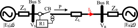
FIGURE 1. Two-machine test system to investigate the impacts of the IBRs penetration on power swing protection.
The relationship between the power transmitted (P) and the angle difference between both ends of the TL (δ) is graphically depicted in Figure 2A, in which the transferred power increases when δ is increasing from 0° to 90°, whereas P decreases after δ goes beyond 90°. During the normal condition, power systems are usually operated well below maximum power transfer angle at 90° (i.e., the point P0 corresponding to δ0 in Figure 2A). Given to (1), the maximum power transferred across the TL in Figure 2 can be derived as:
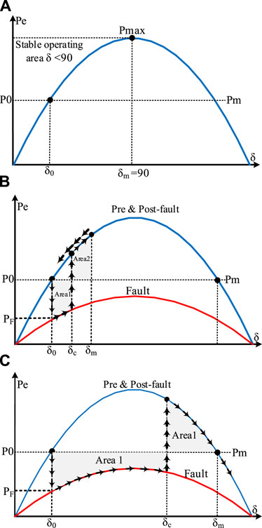
FIGURE 2. (A) The power angle curve, (B) The equal area criteria for a stable swing, (C) The equal area criteria for an unstable swing.
As shown in Figure 2B, once a large disturbance such as a fault occurs on the TL of the two-machine test system in Figure 1, the transferred power is suddenly decreased, causing the electrical output of the machine S to reduce to PF. However, due to the large time constant involved in the mechanical systems coupled with the shaft of the machine, the input power applied to the shaft of the machine, that is, Pm, cannot reduce instantly such that this power imbalance increases the angle δ by accelerating the rotor of the machine during the fault. In this section, for the simplicity of the analysis, the operation of the governors which control the mechanical input of the machine, and the operation of the automatic voltage regulators that control the voltage amplitude at the machine terminals is neglected. Accordingly, assume that the fault is cleared at δc, in which the Pe is greater than Pm. Therefore, as shown in Figure 2B, the rotor of the machine will start to decelerate, while the rotor angle increases to the point of δm. As shown in Figure 2B, at point δm, the Area 1 (accelerating energy) equals Area 2 (decelerating energy), which is known as equal area criteria. In Figure 2B, when the fault is cleared quickly enough such that the Area 2 can be equal with Area 1 before the angle δ reaches δmax, after some oscillations, the system will eventually settle in a new equilibrium point and remain stable. In this condition, the system oscillations are considered as a stable power swing (Verzosa, 2013). On the other hand, as shown in Figure 2C, when the fault clearing time is long enough such that the Area 2 cannot be equal with Area 1 before the angle δ reaches δmax, the system cannot retain its stability. This is because after crossing the point δmax, the Pe will be smaller than Pm, and the rotor of the machine accelerates again and the angle δ continues to increase and goes behind 180°. Under this condition, pole slip occurs and the machine begins to operate at different speeds, causing an unstable power swing or out-of-step (OOS) condition (Verzosa, 2013).
To investigate the impact of fault types on power transferred across a TL during contingencies, the system shown in Figure 1 is considered. For the sake of simplicity, it is assumed that TL, as well as source impedances, are purely inductive. Also, suppose that a fault occurs on the TL at m p. u. distance from the Bus S. In this condition, the corresponding equivalent circuit of Figure 1 can be derived as depicted in Figure 3. Under this condition, depending on the fault type, the effective reactance between the two sources, that is, ES and ER, will increase. With this in mind, as shown in Figure 3, a shunt reactance (XF) connected between the faulted point and the ground can be used to model the fault. Ignoring the fault resistance, as shown in Figure 4, the value of XF for single-line-to-ground (SLG), line-to-line (LL), line-to-line-to-ground (LLG), and three-phase to ground (LLLG) faults can be determined using the interconnection of the sequence networks. In Figure 4, subscribes 0, 1, and 2 refer to zero, positive, and negative sequence impedance of TL as well as sources, respectively (Tziouvaras and Hou, 2004).
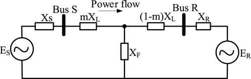
FIGURE 3. Simplified diagram of the two-machine test system with a fault at location m from Bus S.
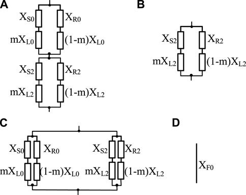
FIGURE 4. Equivalent circuits of the XF for various fault types: (A) SLG, (B) LL, (C) LLG, (D) LLLG.
In the case of a transient fault on TL of the test system shown in Figure 1, after the trip and successful reclosing of CB associated with R1, the power transferred is restored and the transmission line comes back to the service. Accordingly, to illustrate the impact of the equivalent transmission reactance on the power transferred during contingencies, the power angle curve for all possible fault types on TL in Figure 1 are provided in Figure 5. Considering the system shown in Figure 1, in general, among all fault types, the impact of the SLG fault on the equivalent transmission reactance is minimum, while an LLLG fault has maximum effect on the equivalent transmission reactance, as it can block the power transferred between two sources (Tziouvaras and Hou, 2004).
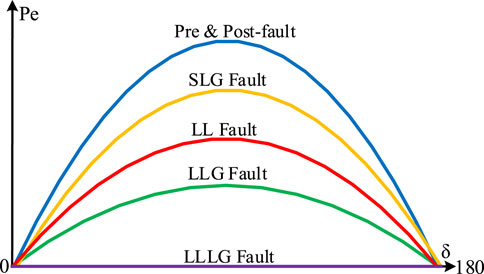
FIGURE 5. Power transmission capability of the two-machine test system during various faults.
To investigate the performance of the legacy power swing protection functions, a two-machine test system shown in Figure 1 is considered. In Figure 1, to investigate the performance of R1, the phasor of the current flowing from Bus S to Bus R, that is, IL, and the phasor of the voltage at Bus S is calculated as (3) and (4) (Upendar et al., 2011; Teimourzadeh et al., 2021).
During the power swing, the frequencies of two machines, fS, and fR, are time-varying variables, so that the rotor angle of the machines can be expressed as (5) and (6) (Verzosa, 2013):
Where δES, δER, fS, and fR are the initial rotor angle of the machine S, the initial rotor angle of the machine R, the frequency of machine S, and the frequency of machine R, respectively. Also, during the power swing, the direction of the current is remained constant, while the relative phase angle difference between the voltages at Bus S and Bus R change. Accordingly, the impedance measured by R1 at Bus S can be expressed as (7):
Assume that δ= δES—δER is the phase angle difference between ES and ER, which has a positive value, and that the ratio of the magnitude of both voltage sources is denoted by K = |ES |/|ER |. Thus, (7) can be written as (8) (Upendar et al., 2011):
When the magnitudes of the voltages at both ends of the TL in Figure 1 are the same, i.e., K = 1, (8) can be simplified as (9):
Finally, the impedance calculated by R1 can be written as (10):
Because δ in Eq. 10 is the phase angle difference between the two sources, the geometrical representation of the impedance locus, measuring by distance protection function of R1 at Bus S, is shown in Figure 6A. As illustrated in Figure 6A, the ratio of the voltage amplitude of both machines (|ES |/|ER |) and the location of the electrical centre of the system determine the locus of the impedance trajectory. Also, in Figure 6A, the straight line intersecting the total system impedance, ZT, at its middle point is called the electrical centre of the swing. When the magnitude of the voltage of both machines are equal, i.e., |ES |/|ER | = 1, the trajectory of the swing locus is a straight line perpendicular to ZT, which passes through the electrical centre of the system, the point in which angle δ is reached 180°. Besides, the swing locus of the point in which δ equals 90° is shown in Figure 6A. Further, as illustrated in Figure 6A, for the situation in which the magnitude of ES is larger than that of ER, the locus of the swing impedance is a large circle passing just above the electrical centre of the system. On the other hand, as illustrated in Figure 6A, when the magnitude of ER is larger than that of ES, the locus of the swing impedance is a large circle just passing the below of the electrical centre of the system. The centre and radius of both circles are a function of K and can be found in (Kimbark, 1995). Likewise, in Figure 6A, the direction of the swing impedance locus depends on the frequency difference between the two machines. This means that the direction of the swing impedance locus moving from the right to the left corresponds with the cases in which fS is bigger than fR, and vice versa. In real power systems, since the voltage magnitude and the machine frequency are not constant and determined by many factors after a disturbance occurs, the system experiences power swings, which can be large enough to cause OOS conditions. Some typical examples of the possible swing impedance trajectories which can be seen by R1 during power swing phenomena are depicted in Figure 6B, in which the characteristic of zone-1 and zone-2 of the distance protection function is shown as well. Figure 6B shows that during power swings, the trajectory of the impedance locus will cross the relay characteristic if the electrical centre is located inside ZL. Also, as shown in Figure 6B, some of the power swing curves can be seen by zone-1 and zone-2 of the distance protection, so that the trip signals can be issued to the corresponding circuit breakers (CB). However, always there is the possibility of malfunction, especially during stable power swings. Accordingly, to prevent the maloperation of the distance protection during power swings, the PSB function is used (Verzosa, 2013).
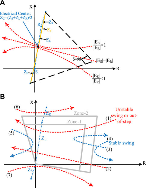
FIGURE 6. The swing impedance trajectory. (A) during various power swing conditions. (B) seen by R1 at Bus S.
Assume that the voltage magnitudes of both sources in Figure 1 are equal; thus, the time derivative of the impedance measured by R1 can be expressed as (Teimourzadeh et al., 2021):
Assuming (12) and (13) as expressed hereunder, (11) can be re-written as (14):
It is clear from Eq. 14, the relative impedance of the sources and TLs, along with slip frequency, which depends on the severity of the disturbance, impacts the rate of change of the impedance during a power swing. In fact, when the positive sequence impedances of both sources are larger than that of TL, the distance protection function may have false operation during stable power swings (Tziouvaras and Hou, 2004). Consequently, any scheme which employs the rate of change of the impedance to detect a power swing will be affected by the impedance of the network as well as the severity of the disturbance. Further, since the relay has only access to the impedance of the TL, i.e., the impedances of both sources are not available for the relay, there is usually difficulty during the rate of change of the impedance estimation.
Unstable power swings, causing loss of synchronism between two areas of power systems or a generator and the rest of the network, can affect the performance of the protection functions of the TLs. This is because, during power swings, variation of the magnitude of the voltage and current as well as the relative phase angle between them can impact the performance of the overcurrent, directional overcurrent, as well as distance protection functions. Indeed, not only during unstable power swings but also during stable ones in which the system can recover and remain stable, the malfunction of some of the mentioned protection functions is probable. As shown in Section 2.3, the positive sequence impedance measured by the distance relay during a power swing is a function of the relative phase angle difference between both ends of the TL. Accordingly, because phase units of distance protection measure the positive sequence impedance during LL as well as LLLG faults, distance protection will operate for a stable or an unstable power swing if the swing impedance locus enters its operating zone. In this regard, since the operating time of zone-1 of distance protection is instantaneous, it will be more prone to maloperation during power swings, while zone-2 of distance protection is prone to maloperation when permissive or blocking pilot protection schemes are employed. Further, depending on the rate of movement of the swing impedance locus as well as the time delay setting of the operating zones of distance protection, the backup zones of distance protection usually do not operate during power swings (Tziouvaras and Hou, 2004).
As mentioned in Section 1, the main purpose of the PSB function is to avoid maloperation of distance protection during power swings. The PSB function operates based on the variation of the voltage and current being gradual (slow) during power swings, mainly determined by the inertia of SGs, while it is nearly a step-change during faults. Apparent impedance measured by the relay can enter into operating zones of the distance protection function during both power swings as well as faults. Since a short circuit is an electromagnetic transient phenomenon, the apparent impedance measured by the relay moves very quickly from the load value to fault value in a short period, i.e., a few milliseconds. Contrarily, since power swing is an electromechanical phenomenon, the time interval in which this process can last is much longer than that of a fault condition. Accordingly, depending on the slip frequency of the swing, the rate of change of apparent impedance trajectory is much slower during power swings than that of fault. For instance, for a situation in which the frequency of the electromechanical oscillation is about 1 Hz, and the apparent impedance takes about half a cycle to enter the relay characteristic, the relay measures the change of impedance at about 0.5 s (Verzosa, 2013).
Besides, during an unstable power swing, when δ across a TL approaches 180°, the measured apparent impedance falls within the characteristic of the distance protection function for a certain TL. Since the measured apparent impedance alone cannot be used to distinguish between fault and power swing, the power swing detection algorithm based on the monitoring of the rate of change of impedance is employed. In this method, to avoid maloperation of the distance protection function during power swings, the difference between the rate of change of the impedance is used to detect power swing and accordingly issue a PSB signal before the apparent impedance enters the operating characteristic of the relay. In this regard, to implement the rate of change of impedance-based measuring method, two impedance measurement element along with a timing device is utilized in a way that if the measured impedance stays within two elements for a predetermined time threshold, the power swing condition is detected and the PSB signal is issued to block distance protection function. For this purpose, various shapes of the impedance measurement elements, including double blinders, concentric polygon, and concentric circles as shown in Figures 7A–C are used.
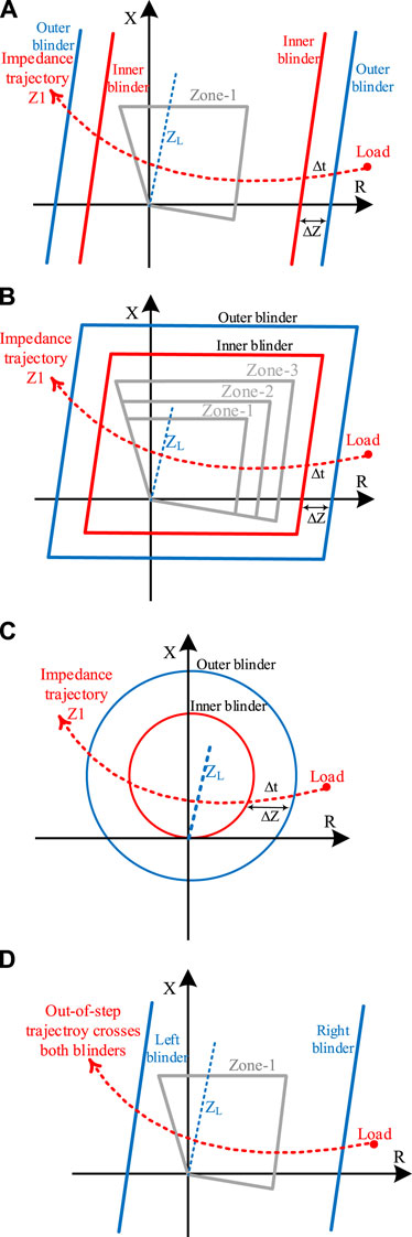
FIGURE 7. Different blinder characteristics. (A) double blinder. (B) concentric polygon. (C) concentric circle. (D) single blinder.
After a power swing is detected, to ensure blocking of the elements of the distance protection function, the inner impedance measurement unit (inner blinder) of the power swing detection logic must cover the largest characteristic of the distance relay. In other words, as depicted in Figure 7, some impedance (ΔZ) has been used to separate both inner and outer blinders. For instance, for a double blinder shape, two sets of parallel blinders are placed on the right as well as the left side of the line impedance to discriminate between faults and power swings through calculating the rate of change of Z1 as described in Eq. 14. As shown in Figure 7A, to implement the process of measuring the rate of change of Z1, the period in which Z1 traverses between the outer and inner blinders, i.e., Δt, is calculated. To do this, once the measured impedance enters the outer blinder, a timer is started. Given a predefined time delay setting, if the measured impedance trajectory remains between both outer and inner blinders for more than a time delay setting, the PSB signal is issued to avoid maloperation of the selected distance zones. A logical block diagram of distance protection incorporated with a PSB function supervised by a directional negative-sequence overcurrent element is presented in Figure 8, in which MPP and PSB denote a phase distance function as well as a PSB signal generated by power swing detection logic, respectively. In Figure 8, the presence of the PSB signal shows that a power swing condition is already detected by the relay under pre-defined user conditions. Also, as shown in Figure 8, to guarantee that the relay only resets PSB signal when the fault detected is in the forward direction, the coordinating delay pick up timer is implemented in a way that a forward directional negative sequence-based element, 32 QF, is supervised by a negative sequence-based overcurrent element, 50 Q (Tziouvaras and Hou, 2004).

FIGURE 8. Logic diagram of a distance element incorporated with a PSB function.
As mentioned in Section 1, the OST function protects power systems during unstable power swings, or OOS conditions, by splitting the network to avoid system collapse. During OOS condition, when two areas of the power system are separated, to avoid equipment damage and further spread of the disturbance, these two areas must be separated from each other in a controlled manner as quickly as possible. This is because uncontrolled tripping of CBs during unstable power swings can cause equipment damage and safety issue for utility personnel. On this basis, in double blinder-based schemes, the OST function can be implemented in the same way as the procedure described above for the PSB function, while the predefined time setting of the timer is shorter in the case of OST than that of PSB. In this regard, during an OST, when the outer blinder is crossed by the swing impedance trajectory, a timer starts; the OOS condition is declared if the impedance trajectory traverses the space between both blinders before the timer expires. Accordingly, either the OST function can be set to trip immediately, trip on the way in, or to wait until the swing impedance locus crosses the inner blinder after the timer expires, trip on the way out (Tziouvaras and Hou, 2004). Immediate tripping of the CBs while the angle difference across the TL approaches 180° can damage them unless CBs have been rated for OOS tripping. Otherwise, the trip on the way-out method along with an additional time delay can be used.
On the other hand, the OOS condition can be detected through a single blinder scheme, which uses a single blinder at both sides of the line impedance, as shown in Figure 7D. In this scheme, the direction in which the impedance trajectory that enters and leaves a blinder needs to be determined. Accordingly, once the swing impedance locus crosses a blinder from one side, a timer starts. The OOS condition will be asserted when the swing impedance trajectory proceeds and crosses the other side blinder provided that the timer is expired. As a result, in this scheme, there is a delay in declaring the OST signal allowing the swing to pass 180° and return to nearly in-phase condition. Further, in some cases, tripping is allowed only when some pole slipping has occurred (Tziouvaras and Hou, 2004; Atienza and Kazemi, 2017).
As stated earlier, for the system shown in Figure 1, the rate of change of impedance is directly influenced by δ which is a function of system inertia. It can be shown that a high penetration level of IBRs can lead to a reduction of the system inertia, faster frequency dynamics, and faster variation of the rate of change of impedance. Since the settings of legacy PSB functions are determined based on the maximum rate of impedance change under 100% penetration of SG, its reliable performance will be adversely affected with the IBR integration, as a faster power swing condition leads to a faster rate of change of impedance trajectory, which will make it difficult for the PSB function to distinguish a fault from a power swing. The high penetration of the IBRs can also affect the proper operation of the OST function since the setting of the OST is defined based on a point on the TL impedance trajectory in which the system cannot regain its stability when a large disturbance occurs. Since the reach of the OST is calculated based on the impedance trajectory under the SG penetration, by increasing the penetration of the IBRs, its performance will be affected as the IBR penetration can alter the swinging impedance trajectory. Thus, with a high penetration of IBRs, it is necessary to revise and recalculate the settings of power swing protection functions.
The IEEE PSRXWG-D6 test system (Upendar et al., 2011) shown in Figure 9 has been used to investigate the impacts of the IBRs penetration on the legacy power swing protection functions. The test system is a 230 kV transmission grid that connects two stations A and D through lines L1 to L4 to an equivalent transmission system denoted by S1. The performance of the PSB and OST functions has been validated under type-III and type-IV WTG and the results are compared with those from the SGs. Each generation station (represented by Bus A and Bus D in Figure 2) incorporates two 250 MVA SG (G1 and G2 are connected to Bus A, while G3 and G4 are connected to Bus D) connected to the grid via identical transformers T1-T4. The model of the SG includes a power system stabilizer, exciter, and governor. The external grid (S1) is modelled by a 230 kV ideal voltage source and a Thevenin impedance. The normal power flow is from the generating station A and D to S1. In Figure 9, to evaluate the performance of the power swing protection functions under IBR penetration, G3 and G4 have been replaced by windfarms WF3 and WF4. The mathematical model and control schemes utilized for the windfarms (WFs) are described in (Muljadi et al., 2008; Brochu et al., 2011). In this paper, the detailed model of the converters is used in the simulation. The model of the WFs includes the aggregate model of 1.5 MW DFIG as well as PMSG-based WTG which are interfaced to the grid via a transformer and WF control system. The model of each WTG consists of mechanical parts, a back-to-back converter represented by a detailed model, a wind turbine transformer, and the converter control scheme. In a large WF including dozens of WTGs, each unit is connected to the substation via an underground collector cable. The modelling of each WTG unit along with its underground cable in detail is computationally intensive, however, it has been shown that a WF can be simulated accurately when an aggregated model of WTGs along with an equivalent model for the underground cable is considered (Muljadi et al., 2008; Brochu et al., 2011). It should be mentioned that the PV farms can be modelled by carrying out the same procedure. Hence, in this paper, the same technique is used to model WFs. In all simulation cases, the rated wind speed is considered, and all WFs supply the same real and reactive power as the SGs to ensure that the test system experiences the same steady-state pre-fault condition.
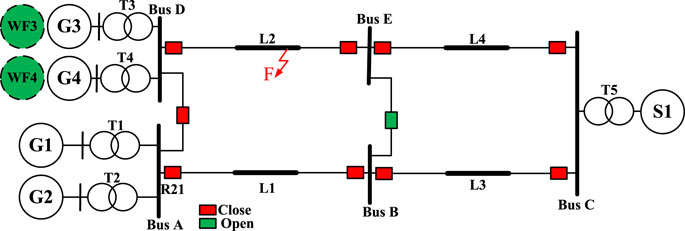
FIGURE 9. The single line diagram of the IEEE PSRCWG-D6 test system including wind farms.
In all simulation cases hereunder, to make a power swing condition, an LLLG fault has been applied at 30 km away from Bus D on line L2, leading to the disconnection of the L2 by the corresponding CBs. Depending on the pre-fault loading condition and fault clearing time, the power swing can be stable or unstable. The fault clearing time can be longer due to a stuck breaker. In the system shown in Figure 9, the power swing condition is created between G1-G4 and the rest of the system because of the acceleration of the generating units and reduced system power transfer capacity during the outage of the faulted line. In all cases, the performance of a multifunctional relay R21 incorporating legacy power swing protection functions, as described in Section 2, installed at substation A is investigated. Further, in all simulated cases, power swing is detected by the PSB functions used for the ground distance functions as well as for the phase distance functions. Also, a self-polarized impedance-based relay with a quadrilateral and large resistive reach is considered. For this purpose, the PSB function employs quadrilateral characteristics in which the reach of the inner and outer blinders is defined as zone-3 and 1.2 times of that of zone-3, respectively (Hashemi and Sanaye-Pasand, 2018). Thus, all three zones of the distance relay are supervised by the power swing protection functions. If the impedance trajectory remains for more than 3 cycles between the inner and outer blinder, the power swing condition will be detected. All the impedances have been measured at the secondary side of the current transformer (CT) and capacitor coupling voltage transformer (CCVT) of R21. The CT ratio is 160 A/1 A and the CCVT ratio is 230 kV/115 V. To adjust all the characteristics of the distance as well as power swing protection functions, it is assumed that the IBRs penetration level is zero, and the setting has been performed for the situation in which G1-G4 are the only generation sources connected to the grid. Also, the reach of zone-1, zone-2, and zone-3 has been adjusted as 80%, 135%, and 200% of L1, respectively. The operating time of zone-1 is instantaneous, while the time delay of zone-2 and zone-3 are 20 and 40 cycles, respectively. In the result provided hereunder, the sampling frequency of R21 is 4 kHz, and the phasors are calculated using the full-cycle discrete Fourier transform.
In this section, the impacts of the integration of type-III and type-IV WTG on the performance of the legacy power swing protection functions, i.e., PSB and OST functions, have been analysed. For this purpose, three integration levels of WTG for five different operational statuses, under various simulation cases have been investigated:
• Status 1: No wind generation: all G1-G4 are considered as SGs.
• Status 2: 25% penetration of type-III WTG (G3 is replaced with WF3).
• Status 3: 25% penetration of type-IV WTG (G3 is replaced with WF3).
• Status 4: 50% penetration of type-III WTG (G3 and G4 are replaced with WF3 and WF4).
• Status 5: 50% penetration of type-IV WTG (G3 and G4 are replaced with WF3 and WF4).
To make a power swing condition, the fault has been applied at t = 0.6 s and cleared at t = 0.8 s by the operation of the breakers installed at both ends of the L2. The measured swinging impedance trajectory under 100% penetration of SG is depicted in Figure 10, which shows that the trajectory of the impedance traverses the space between the outside and inner blinders at about 70 m (more than 4 cycles) which is more than the predefined time delay considered for the PSB function. Thus, the PSB function can easily identify this condition as a power swing and block the relay by issuing a PSB signal to block zone-1, zone-2, and zone-3 of the distance protection function. Hence, even though the impedance trajectory crosses the characteristic of zone-1 of the relay in Figure 10, the maloperation of R21 is prevented, as all three zones have been blocked by the PSB signal.
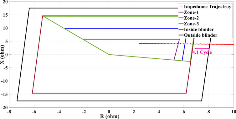
FIGURE 10. Swinging impedance trajectory under 100% penetration of SG penetration (no IBR penetration) and the performance of the conventional PSB function.
In this case study, G3 in Figure 9 is replaced with WF3, and the performance of the PSB function of R21 has been investigated under the same contingency as investigated in Case 1. The result of the swinging impedance trajectory measured by R21 is depicted in Figure 11. As shown, under 25% penetration of type-III WTG, the impedance trajectory traverses the space between the outside and inner blinders in 2.3 cycles which is less than the predefined time delay considered for the PSB function. As shown in Figure 11, after fault occurrence, the impedance trajectory crosses the characteristic of zone-1 of the relay and the PSB function fails to detect the power swing condition to issue a PSB signal to block the distance relay accordingly. Thus, the distance protection function of R21 mistakenly trips the healthy line (L1) immediately by declaring a fault at zone-1.
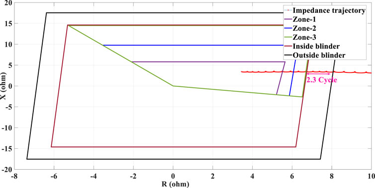
FIGURE 11. Swinging impedance trajectory under 25% penetration of type-III WTG penetration and the performance of the conventional PSB function.
In this case study, the performance of the PSB function has been evaluated during a 25% penetration of type-IV WTG. For this purpose, the fault has been applied at t = 0.6 s and cleared at t = 0.8 s. The measured swinging impedance trajectory by the PSB function of R21 is provided in Figure 12, which shows that under this contingency, the impedance trajectory does not cross the outside blinder which means that the system has experienced lower frequency oscillations in comparison with those in Case 1 and Case 2. So, to increase the frequency oscillations and to have larger power swings, the fault duration is increased to 0.4 s (i.e., fault applied at t = 0.6 s and cleared at 1.0 s). The swinging impedance trajectory measured by R21 is illustrated in Figure 13, which shows that the swinging impedance trajectory traverses the space between both outside and inner blinders in less than 2 cycles (typically 1.5 cycles) which is smaller than the predefined time delay considered for the PSB function. In this regard, as the impedance trajectory crosses the characteristic of zone-1 of the relay, this condition causes the maloperation of R21 by tripping the healthy line, L1.
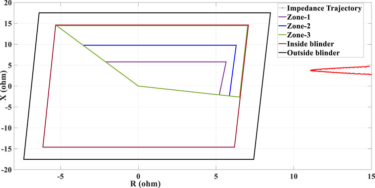
FIGURE 12. Swinging impedance trajectory under 25% penetration of type-IV WTG penetration and the performance of the conventional PSB function during 0.2 s fault duration.
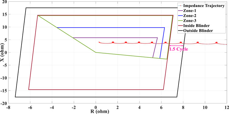
FIGURE 13. Swinging impedance trajectory under 25% penetration of type-IV WTG penetration and the performance of the conventional PSB function during 0.4 s fault duration.
In this case study, the penetration level of type-III WTG is increased to 50%. The same fault condition as Case 2 has been conducted (with a fault duration of 0.2 s). As discussed earlier, increasing the penetration level of the IBRs leads to a faster dynamic response, the result of which is a faster swinging impedance trajectory. The result of the swinging impedance trajectory measured by R21 is shown in Figure 14, which shows that a high share of type-III WTG leads to a faster swinging impedance trajectory such that the impedance trajectory traverses the space between outside and inner blinder in almost 1.2 cycles. Hence, the PSB function of R21 fails to issue a PSB signal while the impedance trajectory crosses the characteristic of zone-1 of R21, leading to the immediate tripping of the healthy line, L1.
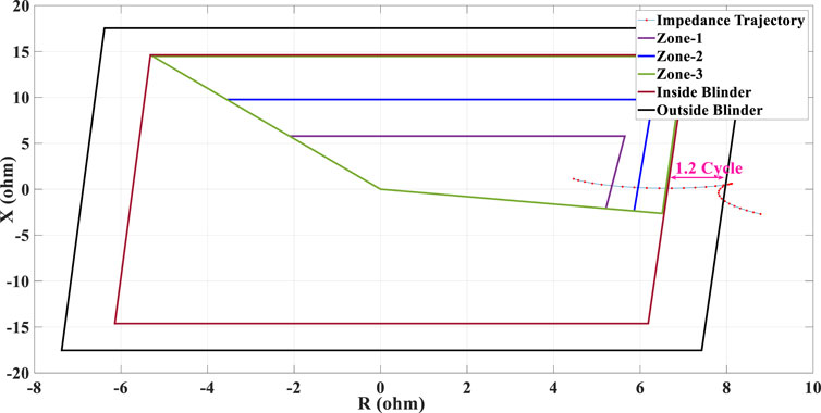
FIGURE 14. Swinging impedance trajectory under 50% penetration of type-III WTG penetration and the performance of the conventional PSB function.
In this case study, the penetration level of type-IV WTG has been increased to 50%. The fault has been applied at t = 0.6 s and removed at t = 0.8 s. Figure 15 shows that for a fault duration of 0.2 s, the swinging impedance trajectory measured by the distance protection function of R21 does not enter the blinder zones. Therefore, to create a more intense power swing condition that allows the evaluation of the performance of the PSB function, the fault duration is increased to 0.4 s (i.e., the fault is applied at 0.6 s and removed at 1.0 s). The swinging impedance trajectory measured by R21 is depicted in Figure 16, which shows that the impedance trajectory traverses the space between the outside and inner blinders in less than 2 cycles which is smaller than the predefined time delay considered for the PSB function. In this condition, the PSB function of R21 cannot detect the power swing condition to issue a blocking signal to all three zones of the distance protection, leading to a spurious trip of the healthy line, L1.
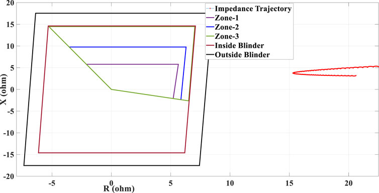
FIGURE 15. Swinging impedance trajectory under 50% penetration of type-IV WTG penetration and the performance of the conventional PSB function during 0.2 s fault duration.
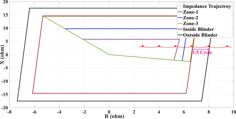
FIGURE 16. Swinging impedance trajectory under 50% penetration of type-IV WTG penetration and the performance of the conventional PSB function during 0.4 s fault duration.
In this case study, the fault has been applied at t = 0.6 s and removed at t = 0.8 s. The swinging impedance trajectory measured by the phase unit of the distance protection function of R21 under 100% SG penetration is shown in Figure 17, which shows that the impedance trajectory enters the right-side blinder at t = 0.86 s and leaves the left side one at t = 1.325 s. In this case, the out-of-step (OOS) condition occurs at t = 1.09 s when the impedance trajectory crosses the imaginary axis. Accordingly, the OST function can identify the OOS condition accurately under 100% SG penetration.
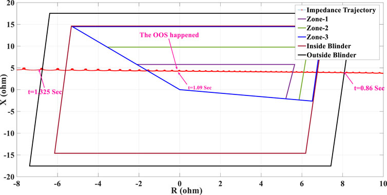
FIGURE 17. Swinging impedance trajectory under 100% penetration of SG and the performance of the conventional OST function.
In this scenario, the OOS condition is created by applying a fault at t = 0.6 s which is removed at t = 0.8 s under 25% penetration of type-III WTG. The swinging impedance trajectory is depicted in Figure 18, which shows that the impedance trajectory enters the right-side blinder and leaves the left-side blinder. In this case, unlike Case 6 in which the impedance trajectory travels the space between the right and left-side blinder in about 0.465 s, by increasing the penetration level of type-III WTG to 25%, the impedance trajectory moves faster and traverses the space between the right and left-side blinder in almost 0.35 s. So, in this case, study, despite the 25% share of WTG, the OST function can detect the OOS condition correctly as well.
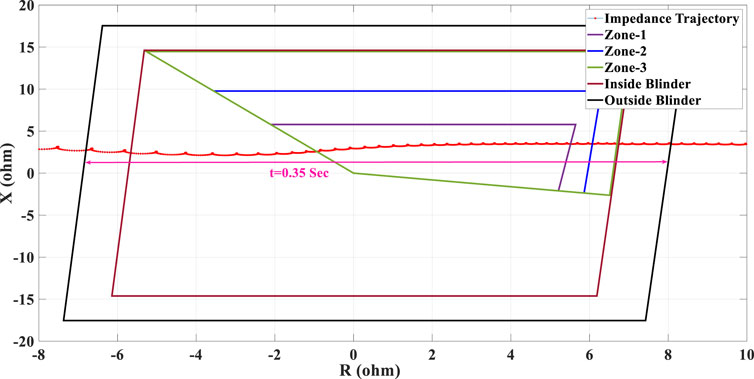
FIGURE 18. Swinging impedance trajectory under 25% type-III WTG penetration and the performance of the conventional OST function.
In this case study, the OST function has been examined under 25% penetration of type-IV WTG. To make an unstable OOS condition, the fault duration is increased to 0.4 s (the fault is applied at t = 0.6 s and removed at 1 s). The swinging impedance trajectory measured by R21 is depicted in Figure 19. As Figure 19 shows, the impedance trajectory enters the right-side blinder and leaves the left side one (and it travels the space between both blinders in almost 0.61 s). Hence, the OST function can correctly detect the unstable power swing and issue the OST tripping signal under the integration of 25% penetration of type-IV WTG.
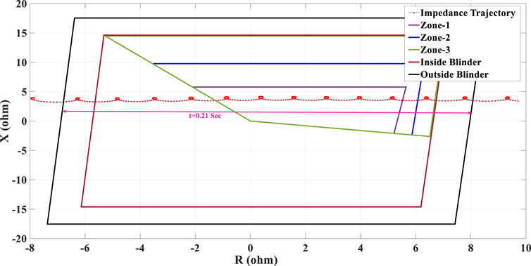
FIGURE 19. Swinging impedance trajectory under 25% penetration of type-IV WTG penetration and the performance of the conventional OST function.
In this case study, the penetration level of type-III WTG is increased to 50%, and the fault is applied at t = 0.6 s and removed at t = 0.8 s. The swinging impedance trajectory measured by the phase unit of the distance protection function of R21 is provided in Figure 20, which shows that the impedance trajectory enters the right-side blinder and moves toward the left-side blinder. However, after crossing the imaginary axis at t = 1.08 s, the point at which the OOS occurs theoretically, the impedance turns its direction and proceeds toward the right-side blinder. Consequently, although the unstable OOS has happened at t = 1.08 s, the conventional OST function cannot detect this situation to issue an OST signal. This situation can create unexpected consequences by avoiding the implementation of controlled islanding scenarios at the predetermined locations with the IBR integration.
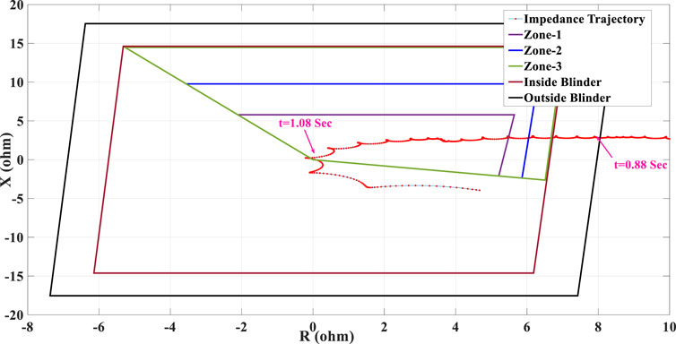
FIGURE 20. Swinging impedance trajectory under 50% penetration of type-III WTG and the performance of the conventional OST function.
In this case study, the performance of the OST function is evaluated under 50% penetration of type-IV WTG. To make an unstable power swing condition, the fault duration has increased to 0.4 s. This means that the fault has been applied at t = 0.6 s, and is removed at t = 1 s. The result of the measured swinging impedance trajectory by phase unit of the distance protection function of R21 is depicted in Figure 21, which shows that the impedance trajectory crosses the right-side blinder as well as the imaginary axis at t = 1.207 s and t = 1.095 s (meaning that unstable OOS condition has occurred at t = 1.207 s), respectively. However, similar to Case 9, after the impedance trajectory enters the right-side blinder and crosses the imaginary axis, it stops moving toward the left-side blinder and turns back, and proceeds toward the right-side blinder. Thus, the conventional OST function fails to detect the unstable OOS condition under the integration of 50% penetration of type-IV WTG.
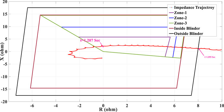
FIGURE 21. Swinging impedance trajectory under 50% penetration of type-IV WTG and the performance of the conventional OST function.
The simulation studies carried out in Section 3 show that the high penetration level of type-III and type-IV WTG increases the rate of change of the swinging impedance trajectory and jeopardizes the reliable operation of the legacy PSB and OST functions. To avoid such maloperations, it has been proposed in (Haddadi et al., 2019) to reduce the predefined time delay considered for the PSB function at a high penetration level of WTG systems. This can be done by adjusting the setting of the PSB function based on the maximum rate of change impedance under a high WTG penetration. This solution works well for the situation in which the share of the WTG system during the power swing is equal to the expected value upon which the setting of the PSB is adjusted. Nevertheless, it is unrealistic to consider a constant share of WTG as the output power of these renewable resources can be affected by a lot of uncertainties. Hence, if the PSB function is set based on a constant share of WTG, it loses its functionality during the SG operation as the rate of change of impedance reduces. Hence, by reducing the predefined time delay considered for the PSB function under SG operation, it is probable that the PSB function mistakenly identifies a fault situation as a power swing condition and blocks the distance relay. Therefore, there is a need to devise new PSB functions in a way that their performance cannot be affected by the IBR integration.
Further, the simulation studies provided in Section 3 prove that under the high share of type-III and type-IV WTG penetration, the conventional OST functions cannot issue the OST signal when the penetration level of the WTG increases. This is because the impedance trajectory does not leave the left-side blinder to allow the OST function to operate. As a result, given the possibility of the maloperation of the conventional OST functions, it is necessary to devise novel OST functions that are immune to the IBR penetration level for transmission grids with a high penetration level of IBRs. According to the (Haddadi et al., 2019), considering the WTG share and type, the WF size and operating conditions, and the GSC strategy, the most stable severe power swing should be defined. However, as mentioned earlier, because of the uncertainty in the produced power of the WTG systems, by adjusting the setting of the power swing protection functions for a high share of WTGs, it is impossible to maintain a secure and reliable operation of the PSB and OST functions when WFs are not available as expected during the process in which the settings of the PSB and OST functions are tuned.
Accordingly, given the simulation studies carried out in the previous sub-sections, the following conclusion can be established:
• A 25% penetration of the IBRs has no significant effect on the performance of the PSB function. However, by increasing the penetration level of the IBRs to 50% for both type-III and type-IV WTGs, due to the reduced system inertia, the rate of change of the swinging impedance trajectory measured by the distance protection is much faster than those measured in the case of SGs or stiff grids. Accordingly, the predefined time delay considered for the PSB function during SG operation does not work under the high penetration of the IBRs.
• At 25% penetration level of type-III and type-IV of WTG, depending on the fault duration, the impedance trajectory enters zone-1 of the distance protection, while the PSB function fails to issue blocking signal, so that the distance protection can issue immediate trip signal, negating any FRT scheme required by the most of the grid codes at high penetration level of IBRs.
• From the simulation results provided in Case 3 and Case 5, for the same fault duration, after fault removal, in the case of type-IV WTG integration, the swinging impedance trajectory approaches the blinder zones but it does not cross the outer blinder. Nonetheless, by increasing the fault duration, the fluctuation of the current and voltage signals increased, causing the impedance trajectory to enter the blinder zone. Thus, it can be concluded that for the same fault duration and share of type-IV and type-III WTG, the impedance trajectory will experience a small swing in the case of a type-IV WTG.
• A 25% penetration of type-III and type-IV WTG integration has no significant effect on the performance of the conventional OST function. However, by increasing the penetration level of the IBRs to 50%, even though the OOS condition has occurred, the conventional impedance-based OST function cannot detect the OST. Hence, the impedance-based OST function cannot retain its secured and reliable performance at a high penetration level of the IBRs.
The conclusion of the paper has been provided in three parts as follows:
A) At a high penetration level of IBRs, to guarantee the safe and reliable operation of the transmission grids, the FRT requirements regulated necessitating IBR units to ride-through faults. Due to the unique fault response of the IBRs, mainly determined by their technology, the performance of the legacy protection functions of the transmission lines, which have been designed to function under only the penetration of the SGs, can be threatened. The maloperation of the protection system during IBRs integration can negate any FRT requirement and even lead to unjustifiable operational status, in the worst case causing a widespread blackout.
B) In this regard, a brief review on the power swing phenomena and its impact on the legacy protection functions of the TLs have been provided. Then, to highlight the vulnerability of the legacy power swing protection functions during IBRs integration, the impacts of integrating type-III and type-IV WTGs, two common types of IBRs, on the legacy PSB and OST functions, which have been designed to function under only SG penetration, have been analysed through a comprehensive set of simulation studies. It has been demonstrated that significant penetration of these WTG systems, can jeopardize the reliable operation of legacy power swing protection functions. This is because the fault currents of type-III and type-IV WTGs are limited by the control scheme of the power electronic converters, which are very different when SGs are the only sources of generation.
C) The simulation studies showed that 50% penetration of type-III and type-IV WTG can threaten the security and reliability of the PSB and OST functions. The critical discussions on the performance of the legacy power swing protection functions of the TLs have been provided under a significant penetration of WTGs. It has been shown that, for the same fault situation, the system experiences a more stable power swing condition in the case of type-IV than type-III WTG. Thus, for a given power system including both type-III and type-IV WTG, the setting of the PSB and OST should be checked independently for each type of WTG system.
All authors listed have made a substantial, direct, and intellectual contribution to the work and approved it for publication.
This work was supported by the Australian Research Council (ARC) and the University of Wollongong.
The authors declare that the research was conducted in the absence of any commercial or financial relationships that could be construed as a potential conflict of interest.
All claims expressed in this article are solely those of the authors and do not necessarily represent those of their affiliated organizations, or those of the publisher, the editors and the reviewers. Any product that may be evaluated in this article, or claim that may be made by its manufacturer, is not guaranteed or endorsed by the publisher.
Alinezhad, B., and Karegar, H. (2017). Out-of-step protection based on equal area criterion. IEEE Trans. Power Syst. 32 (2), 968–977. doi:10.1109/TPWRS.2016.2584121
Banaiemoqadam, A., Hooshyar, A., and Azzouz, M. (2020). A comprehensive dual current control scheme for inverter-based resources to enable correct operation of protective relays, IEEE trans. Power del. Early Access Article.
Behnke, M., Custer, G., Farantatos, E., et al. (2020). Impact of inverter-based resource negative-sequence current injection on transmission system protection. Mexico: Sandia Lab Report.
Brochu, J., Larose, C., and Gagnon, R. (2011). Validation of single- and multiple-machine equivalents for modeling wind power plants. IEEE Trans. Energy Convers. 26 (2), 532–541. doi:10.1109/tec.2010.2087337
EPRI Technical Brief (2019). Impact of inverter-based resources on protection schemes based on negative sequence components. Palo Alto, CA, United States: Electric Power Research Institute.
Fischer, N., Benmouyal, G., Hou, D., Tziouvaras, D., Finely, J., and Smyth, B. (2012). “Do system impedance really affect power swings – applying power swing protection elements without complex system studies,” in 65th Annual Conference for Protective Relay Engineers, New York, 2-5 April 2012 (IEEE).
Haddadi, A., Kosar, I., Karaagac, U., Gras, H., and Farantatos, E. (2019). Impact of wind generation on power swing protection. IEEE Trans. Power Del. 34 (3), 1118–1128. doi:10.1109/tpwrd.2019.2896135
Haddadi, A., Zhao, M., Kocar, I., Karaagac, U., Chan, K. W., and Farantatos, E. (2020). Impact of inverter-based resources on negative sequence quantities-based protection elements,” IEEE trans. Power del. China: Early Access Article.
Hashemi, S. M., and Sanaye-Pasand, M. (2019b). A new predictive approach to wide-area out-of-step protection. IEEE Trans. Ind. Inf. 15 (4), 1890–1898. doi:10.1109/tii.2018.2864153
Hashemi, S. M., and Sanaye-Pasand, M. (2019a). Current-based out-of-step detection method to enhance line differential protection. IEEE Trans. Power Del. 34 (2), 448–456. doi:10.1109/tpwrd.2018.2873698
Hashemi, S. M., and Sanaye-Pasand, M. (2018). Distance protection during asymmetrical power swings: challenges and solutions. IEEE Trans. Power Del. 33 (6), 2736–2745. doi:10.1109/tpwrd.2018.2816304
IEEE PSR WG-D6 (2005). “Power swing and out-of-step considerations on transmission lines,” in IEEE power system relaying and control committee (PSRC) working (USA: Group Rep. WG-D6).
Impact of IEEE Impact of IEEE 1547 standard on smart inverters and the applications in power systems, 2020.
Jalilian, A., and Muttaqi, K. M. (2020). Current-based directional relaying scheme to protect series compensated transmission lines used to transmit bulk power produced by power electronics interfaced renewable energy power plants. IET Generation, Transm. Distribution. 14 (15), 2976–2987. doi:10.1049/iet-gtd.2019.1143
Kou, G., Chen, L., VanSant, P., Velez-Cedeno, F., and Liu, Y. (2020). Fault characteristics of distributed solar generation. IEEE Trans. Power Del. 35 (2), 1062–1064. doi:10.1109/tpwrd.2019.2907462
Muljadi, E., Pasupuati, S., Ellis, A., and Kosterov, D. (2008). Method of equivalencing for a large wind power plant with multiple turbine representation. Pittsburgh, PA, USA, Jul: Presented at the IEEE Power and Energy Soc. Gen. Meeting.
Nagpal, M., Jensen, M., Higginson, M., Bapary, A., Barsch, J., Bloder, M., et al. (2020). “Protection challenges and practices for interconnecting inverter based resources to utility transmission systems,” in IEEE power system relaying and control committee (United States: Working Group C32).
Nayak, P. K., Kumar, A., and Bajpai, P. (2015). Secured zone-3 protection during stressed condition. IEEE Trans. Power Del. 30 (1), 89–96. doi:10.1109/tpwrd.2014.2348992
Paolone, M., Gaunt, T., Guillaudc, X., Liserred, M., Meliopoulose, S., Montif, A., et al. (2020). Fundamentals of power systems modelling in the presence of converter-interfaced generation. Electr. Power Syst. Res. 189, 1–33. doi:10.1016/j.epsr.2020.106811
Paudyal, S., Ramakrishna, G., and Sachdev, M. S. (2010). Application of equal area criterion conditions in the time domain for out-of-step protection. IEEE Trans. Power Del. 25 (2), 600–609. doi:10.1109/tpwrd.2009.2032326
Sharifzadeh, M., Lesani, H., and Sanaye-Pasand, M. (2014). A new algorithm to stabilize distance relay operation during voltage-degraded conditions. IEEE Trans. Power Del. 29 (4), 1639–1647. doi:10.1109/tpwrd.2013.2285502
Teimourzadeh, H., Mohammadi-Ivatloo, B., and Shahidepour, M. (2021). Adaptive protection of partially coupled transmission lines. IEEE Trans. Power Del 36 (1), 429–440. doi:10.1109/tpwrd.2020.2983138
Thakur, S., Das, M., Ashrafi, H., Brahma, S., Finney, D., Fischer, N., et al. (2020). “Application of out-of-step protection schemes for generators,” in IEEE power system relaying and control committee (Working Group J5).
Tziouvaras, D., and Hou, D. (2004). “Out-of-step protection fundamentals and advancements,” in 57th Annual Conference for Protective Relay Engineers, Germany, 1-1 April 2004 (IEEE).
Upendar, J., Gupta, C. P., and Singh, G. K. (2011). Comprehensive adaptive distance relaying scheme for parallel transmission lines. IEEE Trans. Power Del. 26 (2), 1039–1052. doi:10.1109/tpwrd.2010.2090365
Verzosa, Q. (2013). “Realistic testing of power swing blocking and out-of-step tripping functions,” in 66th Annual Conference for Protective Relay Engineers, Germany, 8-11 April 2013 (IEEE).
Zare, H., Yaghobi, H., and Alinejad-Beromi, Y. (2018). Adaptive concept of controlled islanding in power systems for wide-area out-of-step prediction of synchronous generators based on adaptive tripping index. IET Generation, Transm. Distribution 12 (16), 3829–3836. doi:10.1049/iet-gtd.2018.0319
Keywords: power swing protection, distance protection, transmission lines, inverter-based resources, wind turbines, renewable energy
Citation: Jalilian A and Robinson DA (2023) Impact of inverter-based resources on transmission line relaying -part II: power swing protection. Front. Electron. 4:1144383. doi: 10.3389/felec.2023.1144383
Received: 14 January 2023; Accepted: 25 July 2023;
Published: 10 August 2023.
Edited by:
Terence O'Donnell, University College Dublin, IrelandCopyright © 2023 Jalilian and Robinson. This is an open-access article distributed under the terms of the Creative Commons Attribution License (CC BY). The use, distribution or reproduction in other forums is permitted, provided the original author(s) and the copyright owner(s) are credited and that the original publication in this journal is cited, in accordance with accepted academic practice. No use, distribution or reproduction is permitted which does not comply with these terms.
*Correspondence: Amin Jalilian, QW1pbkphbGlsaWFuQFltYWlsLmNvbQ==
Disclaimer: All claims expressed in this article are solely those of the authors and do not necessarily represent those of their affiliated organizations, or those of the publisher, the editors and the reviewers. Any product that may be evaluated in this article or claim that may be made by its manufacturer is not guaranteed or endorsed by the publisher.
Research integrity at Frontiers
Learn more about the work of our research integrity team to safeguard the quality of each article we publish.