 Yajie Jiang
 Yun Yang
95% of researchers rate our articles as excellent or good
Learn more about the work of our research integrity team to safeguard the quality of each article we publish.
Find out more
ORIGINAL RESEARCH article
Front. Electron. , 13 July 2022
Sec. Power Electronics
Volume 3 - 2022 | https://doi.org/10.3389/felec.2022.926865
In this work, the loss (including wire loss and converter loss) of island three-phase AC microgrid is modeled as a quadratic function of the current distribution coefficient, that is, a concave function with equality and inequality constraints. On the basis of the concave optimization principle, the optimal current distribution coefficient of the distributed energy unit (DEU) is calculated online by the double ascent optimization method (DAOM) to minimize the distribution loss. It is proven that the concave function with multi-variables can be optimized by the DAOM. Using the average reactive power distribution scheme, the optimal active power distribution coefficient with the minimum distribution loss of the AC microgrid can be obtained in real time. In addition, given the high R/X ratio in the short-distance AC microgrid, the active power–frequency (P-ω) droop control and reactive power–voltage amplitude (Q-E) droop control are not suitable for power distribution among DEUs. Thus, an advanced strategy comprising active power–voltage amplitude (P-E) droop control and reactive power-frequency (Q-ω) droop control is proposed to dispatch the output active powers and reactive powers of DEUs. Simulation examples are provided to verify the convexity of the proposed model and the effectiveness of the control strategy.
To reverse the trend of the greenhouse effect and reduce carbon emission, reducing loss in modern grid systems is an important research topic (Qian et al., 2020; Jiang et al., 2021a; Li and Roche, 2021). Theoretically, the power loss in the grid can be expressed by the function of the wire resistance matrix and node voltages of distributed energy units (DEUs). Thereby, some studies are carried out on the basis of the wire loss model, such as bus voltage searching (Jiang et al., 2021b) and power flow distribution (Yang et al., 2019). This traditional loss model is easy to change due to the influence of temperature and humidity. Furthermore, only the wire loss can be reduced, whereas the loss of the power converter is not considered. In fact, in an AC microgrid, converter loss may occupy over 50% of the total loss in the distribution network system (Beerten et al., 2012). Therefore, taking this part of loss into account in the control scheme is very important for minimizing the power loss in the distribution network.
As introduced in many research studies and technical manuals, the loss of power in a power electronics converter can be described as a function of the output power. It has been studied in some research works. In the study by Yuan et al. (2021a), the converter loss is further approximated as a quadratic function by the output powers of DEUs. Then, the output active powers and reactive powers of the individual converter are dispatched by the concave allocation algorithm. In the study by Wang et al. (2010) and Teng et al. (2016), one converter-discarding strategy is used to adjust the number of operating converters. In this way, the overall efficiency of parallel-connected inverters is improved according to the demanding power. However, in these works, the potential for reducing converter loss has not been fully developed (Yuan et al., 2021b). Therefore, considering this in the control scheme is very important to minimize the power loss in the distribution network. For the AC microgrid with parallel DEUs, the output current of DEU flows through the corresponding converter and wire resistance to supply power to the load. Compared with a mesh network, there is no complex coupling relationship between output currents. As mentioned earlier, the distributed loss of a single DEU is a quadratic function. The sum of them is the total loss, which is naturally a concave function. Given the balance of energy supply and consumption, this loss model is one concave function. Through the on-line adjustment of current coefficients, the loss of the distribution network can be accurately minimized.
Inspired by the work on the concave optimization–based economical dispatch for generation cost minimization (Akbari-Dibavar et al., 2021), the concave optimization technique such as the dual ascent optimization method (DAOM) is applied in this work to solve the loss minimization problem. In recent years, the concave optimization algorithms, that is, Lagrange multiplier algorithm (Jiang et al., 2021c), dual decomposition algorithm (Jiang et al., 2021d), DAOM (Chen et al., 2017), and alternating direction method of multipliers (ADMM) (Chen and Yang, 2018) have attracted lots of attention for its wide implementations to solve problems in real systems, that is, parallel calculation, power dispatch, machine learning, and game theory. However, some practical problems for the implementation of power electronics should be considered. For example, the computation complexity of the applied algorithm should not affect the closed-loop PWM control of the MCU. By using a centralized data-exchange network, the Lagrange multiplier needs division operation and global data to obtain results (Jiang et al., 2021d), which reduces the scalability in large-scale AC microgrids. In the dual ascent algorithm, the division operation is necessary for current coefficient calculation. By adding a quadratic term of the constraint function, the convergence rate of ADMM is accelerated. However, such operation leads to an increase in computational complexity, which reduces its applicability in real-time high-frequency PWM control. For the DAOM, both Lagrange multiplier and current coefficients can be obtained through simple addition and subtraction iteration for implementation. Thereby, it is reasonable to select the DAOM for concave optimization.
After obtaining the optimal current coefficient, the three-phase converter shall adopt an appropriate active and reactive power distribution strategy. So far, different strategies have been proposed. To achieve accurate power distribution, the droop scheme regulates the output voltage and frequency to compensate for the imbalance among output powers from DEUs (Sun et al., 2017), (Loh et al., 2013). In the study by Sun et al. (2017), the adaptive voltage term is introduced by using active sharing error to regulate the bus voltages. Moreover, this droop scheme is combined with an integrator for power quality improvement (Loh et al., 2013). When inductive reactance plays a leading role in the line, the virtual inductance is generated by the active power dispatch term for frequency regulation (Morstyn et al., 2018).
In the hybrid microgrid, the power balancing control is achieved by one proper-designed interconnection control scheme (Wu et al., 2018). A multi-agent–based power sharing control is used to allocate the power flow to enhance voltage quality (Yang et al., 2020). The voltage error and frequency control are used to regulate the power distribution and bus voltage simultaneously (Yao et al., 2011). Vijay et al. (2021) used the consensus algorithm to adaptively regulate the bus voltage of DEUs according to the measured values of DEU nodes so as to achieve realize bus voltage restoration. So far, relatively little work has been carried out in considering the power loss as the control parameter. Generally, for the scenarios of long-distance AC networks, the wire inductance is large. Thereby, the active power-frequency control is usually applied by considering the inductive impedance. According to the different types of wire, the modified droop strategy has been designed and implemented in the case of pure inductance (Jiang et al., 2021e; Keyvani-Boroujeni et al., 2021; Huang et al., 2022) and pure resistance impedance (Luo et al., 2022), but few research studies explore the complex impedance of the system. In applications, the distance between different converter units is a little far, and the inductance and resistance wire impedance cannot be ignored through the parallel connection of different wires. In addition, due to the possibility of multi-feedback design, the impedance of the power converter is actually very complex. Due to the coupling between the active and reactive power, traditional control cannot achieve efficient power sharing.
As mentioned earlier, the distributed losses of one single DEU in the AC microgrid can be written as a quadratic function. As a combination, the total loss function of the AC microgrid can be obtained. As a multi-variable function, it is proven that the total loss is a concave function with respect to the current distribution coefficients. Furthermore, considering the supply-consumption balance, the proposed total loss model is an equality constrained concave function. In this work, the double ascent optimization method (DAOM) is designed to find the optimal current coefficient. By conducting the Lagrangian model, the optimal current coefficient can be iteratively calculated by the DAOM by simple addition and subtraction. In order to apply the current coefficient to the general PQ control structure, the calculation method of conversion between the current coefficient and power coefficient is designed. With the help of average reactive power, the active power distribution coefficients are obtained by using the voltages and currents of DEUs. For short-distance AC microgrids with a high resistance-to-reactance ratio (for example, R/X = 7.7), the conventional P-ω droop control and Q-E droop control are not suitable for power distribution among DEUs. In this work, an improved adaptive droop control strategy, composed of P-E droop control and Q-ω droop control, is proposed to dispatch the output active powers and reactive powers of DEUs. In this way, a multilayer control structure is proposed, including the DAOM in the top layer, P-E droop control and Q-ω droop control in the second layer, and voltage-current control in the lower layer. Simulation results verify the effectiveness of the proposed control strategy in reducing distribution losses.
Figure 1 shows the typical configuration of the autonomous AC microgrid. In the system, multiple distributed generation (DG) is integrated into one common bus. Power electronic devices such as inverters are generally used as they can provide flexible control of the DGs. To simplify the analysis, we assume that the DGs are all driven through voltage source inverters.
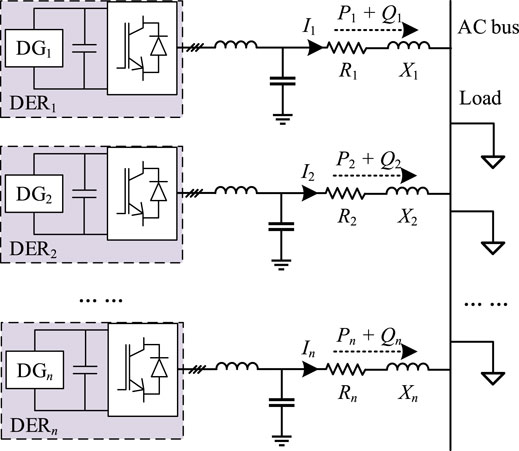
FIGURE 1. Typical AC microgrid.
The power loss in an AC microgrid can be divided into two parts: converter loss
The average conduction loss power in diodes and switches (i.e., PconDi and PconSi) can be given as
where RONi is the ON-state resistance of the semiconductor devices of the ith converter. VONi is the voltages across the semiconductor devices. VFOi is the forward voltages of the diodes. ICi_ave, IFi_ave, ICi_rms, and IFi_rms are the average and root mean square currents of the switches and diodes, respectively. For simplification, the average and root mean square currents of the semiconductor devices can be considered in linear relationships to the output currents of the grid-connected converters. Thus, the average conduction loss of diodes and switches can be expressed as
The average switching loss consists of the turn-on and turn-off loss, which can be calculated based on
where toni and toffi are the turn-on and turn-off time, respectively. fswi is the switching frequency. For simplification, the conduction currents can be considered in linear relationships to the output currents of the converters. Therefore, the average switching loss can be expressed as
The reverse recovery loss power of bypass diodes can be calculated based on
where Vgi is the dc-link voltage of the ith grid-connected converter. tri is the reverse-recovery time. Qrri is the reverse recovery charge of the diodes in the ith grid-connected converter. In a system-level analysis, the average switching loss can be expressed as
In addition, the power loss on resistive elements can be calculated based on
where Rre is the equivalent resistance of the converter.
As given in (1–8), the total power loss of the converter in the DEU system can be expressed as follows
As proposed in the study by Fooladivanda et al. (2021) and Beerten et al. (2012) and the aforementioned analysis, by defining the loss coefficients as ai, bi, and ci, the converter loss is written as
In addition, by adding the wire loss, the total loss is written as
where Ri is the equivalent wire resistance. Based on (11), the loss of the AC microgrid is given as
where Ni is the current distribution coefficient of DEUi, NiItol = Ii, and Itol is the total load currents. Thus, one equality constraint can be obtained as
To reveal the concave characteristic of the loss function, its first-order derivative and second-order derivative are given as
As proven in (14), the loss function is strictly concave. In this work, the cost function to be optimized is given as
where Pmini and Pmaxi are the output power limits.
As presented in Figure 2, the sketch map of the concave function is presented, where the concave function Ploss (Ni) can be seen graphically. Here, the one concave optimization algorithm DAOM is selected for iterative optimization.
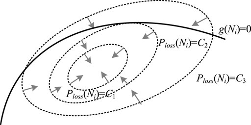
FIGURE 2. Sketch map of the concave optimization.
Based on (15), an augmented Lagrange function is defined as
where λ is the Lagrange multiplier and λ ≠ 0, ρ is a coefficient. As given in the study by Jiang et al. (2021d) and Boyd and Vandenberghe (2004), all calculations for λ and optimal current allocation coefficients are completed in the central controller. With a large number of DEUs, the heavy calculation burden affects the scalability of the given Lagrange multiplier method. Instead of solving the function directly, the DAOM is proposed as an iterative optimization. The idea is to start at an initial guess, take a small step in the direction of the gradient, and repeat. Specifically, we use gradient ascent on the dual variables. The current coefficients can be updated as follows:
The following equation should be satisfied as
which yields
Updating λ based on the residual of the linear constraint, the update rule in the central controller for λ can be expressed as follows:
where α is a coefficient. The main advantage of the DAOM is the parallel execution of Ni updates. It is noteworthy that this inequality constraint will not change the convexity of the proposed loss model. Due to inequality constraints, some current coefficients will be set to constant values. Interestingly, the new loss function formed by the remaining DEUs is still a concave function with respect to the remaining Ni. Thereby, the DAOM can still be used for optimization.
As designed earlier, the current coefficient is obtained for loss minimization. Given the generally used PQ control structure, the current coefficient cannot be applied directly in the AC microgrid. Therefore, the current coefficient should be converged to the power distribution variables for power dispatch. Hence, the relationship between the output current and output power in a DEU is discussed for further control development. In an AC microgrid, the injection power is determined by the ratio of resistance and inductive reactance in the wire. As summarized in Table 1, in a short-distance AC microgrid, the injection active power is determined by the voltage amplitude of the DEU, and the injection reactive power is determined by the frequency of the DEU. The equivalent circuit of DEUi is plotted in Figure 3: Zi = Ri + jXi is the wire impedance, θi is the wire impedance angle, Ei∠φi is the terminal electromotive force of the converter, and Vbus∠0◦ is the voltage of the common AC bus.

TABLE 1. Injected powers under different types of impedances.
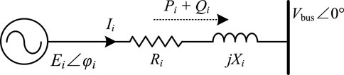
FIGURE 3. Equivalent circuit of the DEUi.
As given in Table 1, the injection power by DEUi is given as
As given in (21), the output active power of the converter is positively correlated with the amplitude of the terminal electromotive force. The output reactive power of the converter is negatively correlated with the operating frequency of the converter. In this way, one droop control is designed as
where ωrefi and ωnom are the reference value and nominal value of angle frequency, respectively, and Erefi and Enom are the reference value and nominal value of angle frequency voltage amplitude, respectively. Meanwhile, the limits of angle frequency and voltage amplitude are also considered in (22): mi and ni are the droop coefficients, Qmaxi is the reactive power limit of the DEUi, ωmin and Emin are the minimum values of angle frequency and voltage amplitude, and ωmax and Emax are the maximum values of angle frequency and voltage amplitude, respectively. According to the apparent power, the output current of the DEUi is
where Vi is RMS values of voltage Ei∠φi. Based on (23), it yields
where Ptol and Qtol are the total demanding powers. NPi and NQi are defined as the active power and reactive power coefficients of DEUi, respectively. Thus, the average reactive power distribution is adopted as
Given the power generation limitation, the active power can be dispatched as
Moreover, a secondary adaptive control layer is implemented as
where xPi = Pi/NPi and xQi = Qi/NQi. xPi and xQi are defined as the inter-media variables for power distribution. Then, the adaptive voltage and frequency terms are generated as
where kEpi, kEIi, kωPi, and kωIi are the gains of controllers. Thus, the secondary control is formed as
As plotted in Figure 4, the proposed P-E and Q-ω control are presented in (a), and the diagram is given in (b). Based on the concave loss model, the optimal current distribution coefficients of each inverter are computed according to the DAOM. By using average reactive power sharing, the active power distribution coefficients are calculated. In addition, the output power of each DEU is calculated locally. Then, these coefficients are incorporated into the local droop controller to perform optimum power sharing. The reference values of angle frequency and voltage amplitude by adaptive droop control are further used for local voltage and current closed-loop control. In this way, the concave optimization–based current and power sharing for distribution loss minimization is achieved.
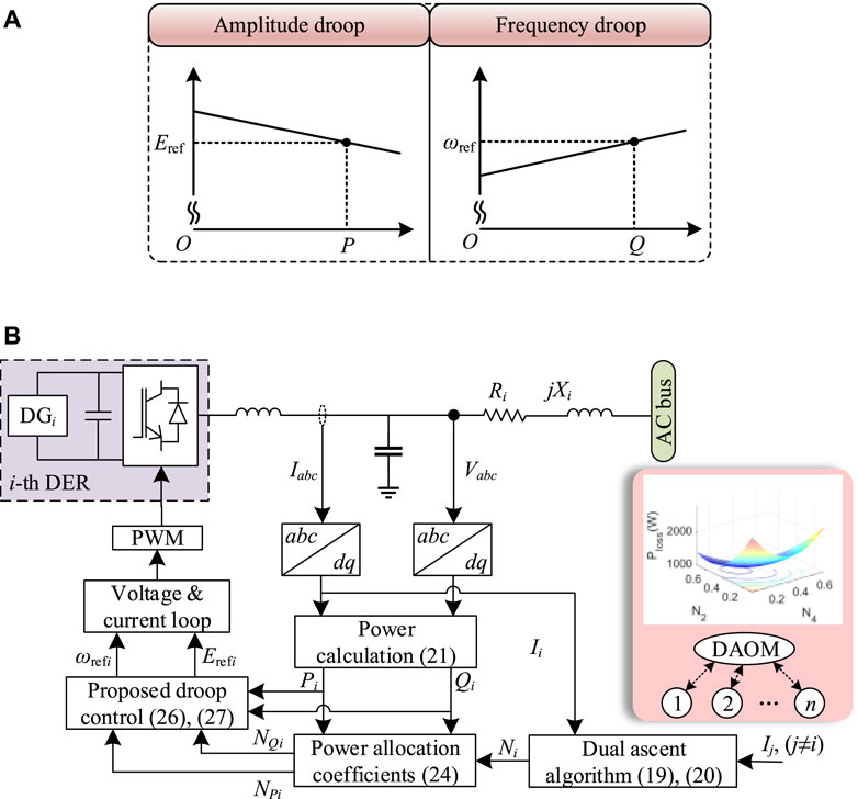
FIGURE 4. (A) P-E droop control and Q-ω droop control, (B) proposed schematic control diagram of three-phase power converters.
The simulation-based case study is conducted in MATLAB/Simulink with four DEU systems. The main parameters of the AC microgrid are shown in Table 2. In this work, the loads are considered current sinks whose current. The allowable voltage deviations are Vmin = 209 V and Vmax = 231 V. The rated power of the four DEU systems is given as 4 kW. The algorithm execution period of the DAOM is set to 1s. The PWM frequency and the sampling frequency of the local closed-loop control are 10 kHz. For DEU systems 1, 2, 3, and 4, the converter loss coefficients are presented in Table 3.
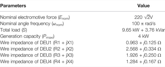
TABLE 2. Parameters of AC microgrids.
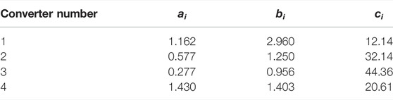
TABLE 3. Converter loss coefficients.
The convexity of the loss model is preliminarily verified by the exhaustive search method in the simulation model. By fixing the change step of the current coefficient, the new coefficient is continuously brought into the AC microgrid to obtain the loss value. For example, the DEU2 and DEU3 are selected to form an AC microgrid. Then, the distribution losses with respect to current coefficients under different load currents (8, 12, 16, and 20 A) are plotted in Figure 5A. The loss curves of another AC microgrid with DEU1 and DEU4 are also presented in Figure 5B. Due to the equality constraint, only one coefficient can be adjusted for an AC microgrid in the case of two DEUs. As can be seen, both eight curves in Figure 5 are conic with one minimum point.
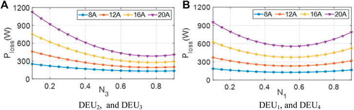
FIGURE 5. AC microgrid loss with two DEUs. (A) DEU2 and DEU3, (B) DEU1 and DEU4.
Furthermore, two current coefficients can be regulated in the searching process for the three DEU-based AC microgrid under 30 A load current. Therefore, the system loss can be drawn as a three-dimensional surface. As given in Figure 6, four loss surfaces correspond to four different DEU combinations: DEU1, DEU2, and DEU3 in Figure 6A, DEU1, DEU2, and DEU4 in Figure 6B, DEU1, DEU3, and DEU4 in Figure 6C, and DEU2, DEU3, and DEU4 in Figure 6D). The contours of the losses are also projected onto the bottom surface. Apparently, both surfaces with openings upward are smooth, which are the typical concave surfaces.
FIGURE 6. Loss with three DEU systems. (A) DEU1, DEU2, and DEU3, (B) DEU1, DEU2, and DEU4, (C) DEU1, DEU3, and DEU4, (D) DEU2, DEU3, and DEU4.
For the system with four DEUs, the loss surface cannot be plotted directly with three adjustable variables. Therefore, we can fix the current coefficient value of one DEU so as the loss model degenerates into a three-dimensional surface. The total load current is 48 A. By fixing the one current coefficient at 0.1 in turn, four three-dimensional loss surfaces are obtained in Figure 7. Obviously, both surfaces with an opening upward are smooth, which are typical concave functions. For an AC microgrid with more DEUs, the convexity of the proposed loss model cannot be graphically illustrated. However, as shown in the previous figures, the theoretical proof has been provided in Section 2
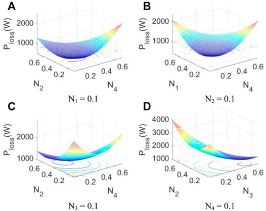
FIGURE 7. Distribution loss with respect to current coefficients for fixed (A) N1, (B) N2, (C) N3, and (D) N4.
Optimal control studies by the proposed DAOM and the P-E and Q-ω control are also presented based on the aforementioned analyzed AC distribution network. In case 1, the traditional control and the proposed control are adopted for the four DEUs in the periods from 0 to 3 s and 3–32 s, respectively. Figure 8 shows the waveforms of the voltages, output currents, current distribution coefficients, active powers, active power allocation coefficients, reactive powers, reactive power allocation coefficients for the DEUs in the AC microgrid, and the loss. At the initial condition, the current coefficients of DEUs are N1 = 0.33, N2 = 0.18, N3 = 0.21, and N4 = 0.28, and the output active power allocation coefficients of DEUs are NP1 = 0.34, NP2 = 0.17, NP3 = 0.21, and NP4 = 0.28. The output powers are P1 = 3.3 kW, P2 = 1.6 kW, P3 = 2.0 kW, and P4 = 2.75 kW and Q1 = Q2 = Q3 = Q4 = 0.94 kVar. These output power and current allocation rates are determined by the different wire impedances and voltage for DEUs. Meanwhile, b uses the converter loss coefficients and wire resistances in Tables 2 and 3, and the loss is calculated as 1097 W (converter loss is 812 W, and the wire loss is 285 W).
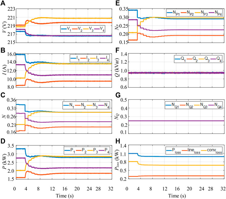
FIGURE 8. (A) Voltages, (B) output currents, (C) current distribution coefficients, (D) active powers, (E) active power allocation coefficients, (F) reactive powers, (G) reactive power allocation coefficients, and (H) power loss.
When the proposed DAOM is applied at 3 s, the current distribution coefficients, active power allocation coefficients, and reactive power allocation coefficients are continuously updated in a cycle of 1 s. At the same time, the distributed secondary control regulates the output active powers and reactive powers according to the updating power ratio. After iteration, the current distribution coefficients are optimized at N1∗ = 0.29, N2∗ = 0.20, N3∗ = 0.28, and N4∗ = 0.23 at steady state. The results are coincided with the minimum point of the proposed loss model by the concave optimization theory. With the help of NQi = 0.25, the optimal active power allocation coefficients are obtained as N∗P1 = 0.29, N∗P2 = 0.19, N∗P3 = 0.29, and N∗P4 = 0.23. Then, the output powers from DEUs are distributed as 2.8, 1.85, 2.83, and 2.17 kW by the designed P-E and Q-ω droop controls. By using the aforementioned parameters, the coefficient updating process of the DAOM is smooth, with the well regulation of output currents. The corresponding wire loss, converter loss, and distribution loss by the designed control are 306 W, 680 W, and 986 W, respectively. By comparing with the conventional method, the wire loss is increased by 21 W, while the converter loss is decreased by 132 W. Therefore, the total distribution power loss of the proposed control is reduced by 111 W (reduced by 10.12%). Furthermore, the output powers and bus voltages of DEUs are controlled within the limitations during the whole control process. The final convergence values of current coefficients and active power coefficients are presented in Table 4. These values are consistent with the theoretical minimum point of the loss model. Therefore, both DAOM P-E droop control and Q-ω droop control are proven.
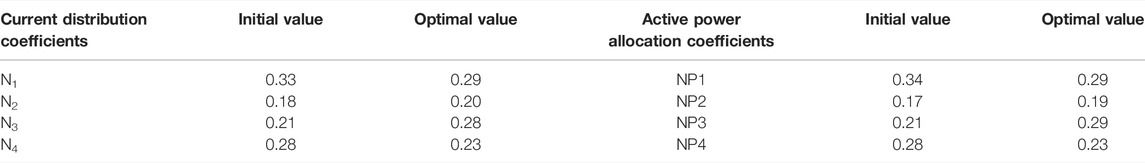
TABLE 4. Control results of case 1.
In case 2, the study on the variation of wire resistance is carried out: R3 is revised as 0.214 Ω (Pecht et al., 2017; Zhang et al., 2019; Singh et al., 2020). Figure 9 shows the control results of the voltages, output currents, current allocation coefficients, active powers, active power allocation coefficients, reactive powers, reactive power allocation coefficients for the DEUs, and the loss. At the initial condition, the current coefficients of DEUs are N1 = 0.30, N2 = 0.22, N3 = 0.22, and N4 = 0.26 and the output active power allocation coefficients of DEUs are NP1 = 0.30, NP2 = 0.21, NP3 = 0.22, and NP4 = 0.26. The output powers are P1 = 2.9 kW, P2 = 2.05 kW, P3 = 2.05 kW, and P4 = 2.65 kW and Q1 = Q2 = Q3 = Q4 = 0.94 kVar. These output power and current allocation rates are determined by the different wire impedances and voltage for DEUs. Meanwhile, b using the converter loss coefficients and wire resistances in Tables 2 and 3, the loss is calculated as 999 W (the converter loss is 748 W, and the wire loss is 251 W).
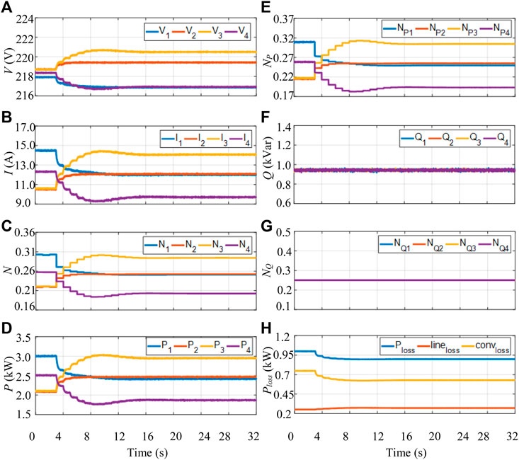
FIGURE 9. (A) Voltages, (B) output currents, (C) current distribution coefficients, (D) active powers, (E) active power allocation coefficients, (F) reactive powers, (G) reactive power allocation coefficients, and (H) power loss.
When the proposed DAOM is applied at 3 s, the current distribution coefficients, active power allocation coefficients, and reactive power allocation coefficients are continuously updated in a cycle of 1 s. At the same time, the distributed secondary control regulates the output active powers and reactive powers according to the updating power ratio. After iteration, the current distribution coefficients are optimized at N1∗ = 0.25, N2∗ = 0.25 N3∗ = 0.30 and N4∗ = 0.20 at steady state. The results are coincided with the minimum point of the proposed loss model by the concave optimization theory. With the help of NQi = 0.25, the optimal active power allocation coefficients are obtained as N∗P1 = 0.250, N∗P2 = 0.255, N∗P3 = 0.305, and N∗P4 = 0.190. Then, the output powers from DEUs are distributed as 2.40, 2.46, 2.94, and 1.85 kW by the designed P-E and Q-ω droop control. By using the aforementioned parameters, the coefficient updating process of the DAOM is smooth, with the well regulation of output currents. The corresponding wire loss, converter loss, and distribution loss by designed control are 271, 628, and 899 W, respectively. By comparing with the conventional method, the wire loss is increased by 20 W, while the converter loss is decreased by 120 W. Therefore, the total loss of the proposed control is reduced by 100 W (reduced by 10.01%). Moreover, the bus voltages and output powers of DEUs in Figure 9 are regulated within the limitations. The iteration results by the DAOM of case 2 are given in Table 5. The optimal values of the current and active power allocation coefficients coincide with the theoretical analysis.
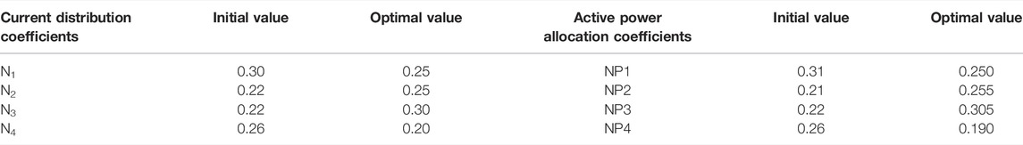
TABLE 5. Control results of case 2.
Figure 10 shows the loss comparison. Compared with the traditional method, this control scheme reduces the power loss of the distribution network by about 10.12 and 10.01% in case 1 and case 2, respectively.
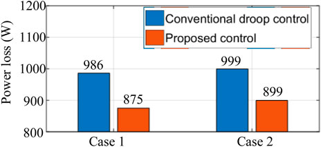
FIGURE 10. Loss comparison.
The wire loss and converter loss in the AC microgrid are modeled as a function of the current distribution coefficient. As analyzed, the loss model is a concave function with constraints. By applying the DAOM, the optimal current coefficients for DEUs are obtained by iteration. Then, according to the wire impedance in a short-distance AC microgrid, the novel P-E droop control and Q-ω droop control are proposed to dispatch the output active powers and reactive powers of DEUs. Hence, real-time loss minimization control is achieved. Case studies are provided to verify the convexity of the proposed model and the effectiveness of the control strategy.
The original contributions presented in the study are included in the article/Supplementary Material; further inquiries can be directed to the corresponding author.
All authors listed have made a substantial, direct, and intellectual contribution to the work and approved it for publication.
The authors declare that the research was conducted in the absence of any commercial or financial relationships that could be construed as a potential conflict of interest.
All claims expressed in this article are solely those of the authors and do not necessarily represent those of their affiliated organizations, or those of the publisher, the editors, and the reviewers. Any product that may be evaluated in this article, or claim that may be made by its manufacturer, is not guaranteed or endorsed by the publisher.
Akbari-Dibavar, A., Mohammadi-Ivatloo, B., Zare, K., Khalili, T., and Bidram, A. (2021). Economic-emission Dispatch Problem in Power Systems with Carbon Capture Power Plants. IEEE Trans. Ind. Appl. 57 (4), 3341–3351. doi:10.1109/tia.2021.3079329
Beerten, J., Cole, S., and Belmans, R. (2012). Generalized Steady-State VSC MTDC Model for Sequential AC/DC Power Flow Algorithms. IEEE Trans. Power Syst. 27 (2), 821–829. doi:10.1109/tpwrs.2011.2177867
Chen, G., Li, C., and Dong, Z. (2017). Parallel and Distributed Computation for Dynamical Economic Dispatch. IEEE Trans. Smart Grid 8 (2), 1026–1027. doi:10.1109/TSG.2016.2623980
Chen, G., and Yang, Q. (2018). An ADMM-Based Distributed Algorithm for Economic Dispatch in Islanded Microgrids. IEEE Trans. Ind. Inf. 14 (9), 3892–3903. doi:10.1109/tii.2017.2785366
Fooladivanda, D., Hu, Q., and Chang, Y. H. (2021). Secure Dynamic State Estimation for Cyber Security of AC Microgrids. Front. Control. Eng. 2, 734220. doi:10.3389/fcteg.2021.734220
Huang, W., Shuai, Z., Shen, X., Li, Y., and Shen, Z. J. (2022). Dynamical Reconfigurable Master–Slave Control Architecture (DRMSCA) for Voltage Regulation in Islanded Microgrids. IEEE Trans. Power Electron. 37 (1), 249–263. doi:10.1109/TPEL.2021.3099482
Jiang, Y., Yang, Y., Tan, S.-C., and Hui, S.-Y. R. (2021). Distribution Power Loss Mitigation of Parallel-Connected Distributed Energy Resources in Low-Voltage DC Microgrids Using a Lagrange Multiplier-Based Adaptive Droop Control. IEEE Trans. Power Electron. 36 (8), 9105–9118. doi:10.1109/tpel.2021.3050506
Jiang, Y., Yang, Y., Tan, S.-C., and Hui, S. Y. (2021). Distributed Sliding Mode Observer-Based Secondary Control for DC Microgrids under Cyber-Attacks. IEEE J. Emerg. Sel. Top. Circuits Syst. 11 (1), 144–154. doi:10.1109/jetcas.2020.3046781
Jiang, Y., Yang, Y., Tan, S. C., and Hui, S. Y. R. (2021). A High-Order Dixfferentiator Based Distributed Secondary Control for Dc Microgrids against False Data Injection Attacks. IEEE Trans. Smart Grid. early access. doi:10.1109/TSG.2021.3135904
Jiang, Y., Yang, Y., Tan, S. C., and Hui, S. Y. R. (2021). “Lagrange Multiplier-Based Optimization Control for Distribution Power Loss Minimization of Islanded Three-phase AC Microgrids,” in 2021 IEEE/IAS Industrial and Commercial Power System Asia (Chengdu, China: I&CPS Asia), 489–494. doi:10.1109/icpsasia52756.2021.9621641
Jiang, Y., Yang, Y., Tan, S. C., and Hui, S. Y. R. (2021). “Power Loss Mitigation of Parallel-Connected Distributed Energy Resources in DC Microgrids Using a Dual-Ascent Hierarchical Control,” in Proc. 2021 IEEE IAS Industrial & Commercial Power System Asia, Chengdu, China, 18-21 July 2021. doi:10.1109/icpsasia52756.2021.9621706
Keyvani-Boroujeni, B., Fani, B., Shahgholian, G., and Alhelou, H. H. (2021). Virtual Impedance-Based Droop Control Scheme to Avoid Power Quality and Stability Problems in VSI-Dominated Microgrids. IEEE Access 9, 144999–145011. doi:10.1109/access.2021.3122800
Li, B., and Roche, R. (2021). Real-Time Dispatching Performance Improvement of Multiple Multi-Energy Supply Microgrids Using Neural Network Based Approximate Dynamic Programming. Front. Electron. 1. doi:10.3389/felec.2021.637736
Loh, P. C., Li, D., Chai, Y. K., and Blaabjerg, F. (2013). Autonomous Control of Interlinking Converter with Energy Storage in Hybrid AC–DC Microgrid. IEEE Trans. Ind. Appl. 49 (3), 1374–1382. doi:10.1109/TIA.2013.2252319
Luo, S., Wu, W., Koutroulis, E., Chung, H. S. H., and Blaabjerg, F. (2022). A New Kalman-Filter-Based Harmonic Current Suppression Method for the Virtual Oscillator Controlled Grid-Tied Inverter. IEEE, J. Emer. Sel. Top. Circuits Syst. 12 (1). doi:10.1109/jetcas.2022.3141106
Morstyn, T., Hredzak, B., and Agelidis, V. G. (2018). Network Topology Independent Multi-Agent Dynamic Optimal Power Flow for Microgrids with Distributed Energy Storage Systems. IEEE Trans. Smart Grid 9 (4), 3419–3429. doi:10.1109/tsg.2016.2631600
Pecht, M. G., Agarwal, R., McCluskey, P., Dishongh, T., Javadpour, S., and Mahajan, R. (2017). Electronic Packaging: Materials and Their Properties. Boca Raton, FL: CRC Press.
Qian, X., Yang, Y., Li, C., and Tan, S.-C. (2020). Operating Cost Reduction of DC Microgrids under Real-Time Pricing Using Adaptive Differential Evolution Algorithm. IEEE Access 8, 169247–169258. doi:10.1109/access.2020.3024112
Singh, R. S., Cobben, S., and Ćuk, V. (2020). PMU-based Cable Temperature Monitoring and Thermal Assessment for Dynamic Line Rating. IEEE Trans. Power Del. 36 (3), 1859–1868. doi:10.1109/TPWRD.2020.3016717
Sun, Y., Hou, X., Yang, J., Han, H., Su, M., and Guerrero, J. M. (2017). New Perspectives on Droop Control in AC Microgrid. IEEE Trans. Ind. Electron. 64 (7), 5741–5745. doi:10.1109/tie.2017.2677328
Teng, J. H., Liao, S.-H., Huang, W.-H., and Chiang, C. C. (2016). Smart Control Strategy for Conversion Efficiency Enhancement of Parallel Inverters at Light Loads. IEEE Trans. Ind. Electron. 63 (12), 7586–7596.
Vijay, A. S., Parth, N., Doolla, S., and Chandorkar, M. C. (2021). An Adaptive Virtual Impedance Control for Improving Power Sharing Among Inverters in Islanded AC Microgrids. IEEE Trans. Smart Grid 12 (4), 2991–3003. doi:10.1109/tsg.2021.3062391
Wang, H., Khambadkone, A. M., and Yu, X. (2010). Control of Parallel Connected Power Converters for Low Voltage Microgrid-Part II: Dynamic Electrothermal Modeling. IEEE Trans. Power Electron. 25 (12), 2971–2980. doi:10.1109/tpel.2010.2087394
Wu, X., Shen, C., and Iravani, R. (2018). A Distributed, Cooperative Frequency and Voltage Control for Microgrids. IEEE Trans. Smart Grid 9 (4), 2764–2776. doi:10.1109/tsg.2016.2619486
Yang, Y., Qin, Y., Tan, S.-C., and Hui, S. Y. R. (2019). Efficient Improvement of Photovoltaic-Battery Systems in Standalone DC Microgrids Using a Local Hierarchical Control for the Battery System. IEEE Trans. Power Electron. 34 (11), 10796–10807. doi:10.1109/tpel.2019.2900147
Yang, Y., Qin, Y., Tan, S.-C., and Hui, S. Y. R. (2020). Reducing Distribution Power Loss of Islanded AC Microgrids Using Distributed Electric Springs with Predictive Control. IEEE Trans. Ind. Electron. 67 (10), 9001–9011. doi:10.1109/tie.2020.2972450
Yao, W., Chen, M., Matas, J., Guerrero, J. M., and Qian, Z.-M. (2011). Design and Analysis of the Droop Control Method for Parallel Inverters Considering the Impact of the Complex Impedance on the Power Sharing. IEEE Trans. Ind. Electron. 58 (2), 576–588. doi:10.1109/tie.2010.2046001
Yuan, W., Wang, Y., and Chen, Z. (2021). New Perspectives on Power Control of AC Microgrid Considering Operation Cost and Efficiency. IEEE Trans. Power Syst. 36 (5), 4844–4847. doi:10.1109/tpwrs.2021.3080141
Yuan, W., Wang, Y., Liu, D., Deng, F., and Chen, Z. (2021). Efficiency-prioritized Droop Control Strategy of AC Microgrid. IEEE J. Emerg. Sel. Top. Power Electron. 9 (3), 2936–2950. doi:10.1109/jestpe.2020.2967756
Keywords: AC microgrid, concave optimization, distributed energy unit (DEU), distribution loss, double ascent optimization method (DAOM)
Citation: Jiang Y and Yang Y (2022) Dual Ascent Algorithm-Based Improved Droop Control for Efficient Operation of AC Microgrid. Front. Electron. 3:926865. doi: 10.3389/felec.2022.926865
Received: 23 April 2022; Accepted: 27 May 2022;
Published: 13 July 2022.
Edited by:
Yanbo Wang, Aalborg University, DenmarkCopyright © 2022 Jiang and Yang. This is an open-access article distributed under the terms of the Creative Commons Attribution License (CC BY). The use, distribution or reproduction in other forums is permitted, provided the original author(s) and the copyright owner(s) are credited and that the original publication in this journal is cited, in accordance with accepted academic practice. No use, distribution or reproduction is permitted which does not comply with these terms.
*Correspondence: Yun Yang, eXVueWFuZ0Bwb2x5dS5lZHUuaGs=
Disclaimer: All claims expressed in this article are solely those of the authors and do not necessarily represent those of their affiliated organizations, or those of the publisher, the editors and the reviewers. Any product that may be evaluated in this article or claim that may be made by its manufacturer is not guaranteed or endorsed by the publisher.
Research integrity at Frontiers
Learn more about the work of our research integrity team to safeguard the quality of each article we publish.