- BioElectronic Vision Lab, University of Michigan, Ann Arbor, MI, United States
Independent travelling is a significant challenge for visually impaired people in urban settings. Traditional and widely used aids such as guide dogs and long canes provide basic guidance and obstacle avoidance but are not sufficient for complex situations such as street crossing. We propose a new wearable system that can safely guide a user with visual impairment at a signalized crosswalk. Safe street crossing is an important element of fully independent travelling for people who are blind or visually impaired (BVI), but street crossing is challenging for BVI because it involves several steps reliant on vision, including scene understanding, localization, object detection, path planning, and path following. Street crossing also requires timely completion. Prior solutions for guiding BVI in crosswalks have focused on either detection of crosswalks or classifying crosswalks signs. In this paper, we demonstrate a system that performs all the functions necessary to safely guide BVI at a signalized crosswalk. Our system utilizes prior maps, similar to how autonomous vehicles are guided. The hardware components are lightweight such that they can be wearable and mobile, and all are commercially available. The system operates in real-time. Computer vision algorithms (Orbslam2) localize the user in the map and orient them to the crosswalk. The state of the crosswalk signal (don’t walk or walk) is detected (using a convolutional neural network), the user is notified (via verbal instructions) when it is safe to cross, and the user is guided (via verbal instructions) along a path towards a destination on the prior map. The system continually updates user position relative to the path and corrects the user’s trajectory with simple verbal commands. We demonstrate the system functionality in three BVI participants. With brief training, all three were able to use the system to successfully navigate a crosswalk in a safe manner.
1 Introduction
Vision loss is a significant health issue worldwide. It is estimated that 82.7 million people around the world are considered blind or severely visually impaired (Bourne et al., 2020). Those who are blind or visually impaired (BVI) will increase with a growing ageing population, with one study estimating 703 million people will have moderate to severe visual impairment by the year 2050 despite emerging clinical treatments (Ackland et al., 2017). Loss of vision can cause reduced quality of life regarding emotional well-being, activity, and social relationships (Lamoureux and Pesudovs, 2011; Duncan et al., 2017; Lange et al., 2021) as well as mobility (National Academies of Sciences, 2017). Vision loss significantly and negatively impacts the ability to travel with confidence and safety due to the inability to obtain proper information about the nearby environment. Difficulty with mobility has been linked to deficits in visual acuity, visual field, contrast sensitivity, or depth perception (Marron and Bailey, 1982; Lord and Dayhew, 2001; Bibby et al., 2007).
Recently, wearable systems to aid wayfinding for BVI have been evaluated in humans. Brainport is a sensory substitution device that provides sensation related to vision (patterned electrical stimulation of the tongue based on images captured by a camera), but mobility is slower than what can be achieved with a guide dog or long cane (Nau et al., 2015; Grant et al., 2016). Mobile technology, such as smartphones, tablets, and augmented reality headsets, provide an off-the-shelf, programmable platform to support wayfinding. Many experimental and commercial systems exist with varying degrees of functionality. See Kuriakose et al. (2020) for a recent review of this field. Some examples include Navcog3 (Sato et al., 2017), which is a navigation system based on smartphones and beacons to localize users in a shopping-mall. “AIRA” is a commercial smartphone-based aid tool to connect users with VI to trained live agents who provide instructions to AIRA users. ISANA (Li et al., 2018) is a chest-worn navigation system using Google Tango that can stream RGB-D image data. AR headset technology (or smart glasses) offers the benefit of a headworn camera, which may aid in exploring a scene and see through displays, which will allow highlight important areas, but will require a BVI user to have enough remaining vision to see the display. The wearable systems use computer vision algorithms to perform functions such as facial or object recognition and character reading. To guide mobility, these mobile systems cue the user with verbal, vibrational, and simplified visual signals (Lee and Medioni, 2011; Coughlan and Shen, 2013; Adebiyi et al., 2017; Wang et al., 2017).
In this paper, we select street crossing as a specific scenario since this demands a series of tasks typically guided by vision, and thus represents a major challenge for BVI. Tasks involved with street crossing include orientation towards the correct crosswalk, determining the crosswalk signal state, beginning to walk at the appropriate time, maintaining a proper path, and completing the task within a limited amount of time.
Several crosswalk navigation systems have been reported. CrossNavi can recognize white stripes of crosswalks using a smartphone camera attached on a customized cane. The system provides proper feedback to maintain user trajectory on the crosswalk while crossing a street (Shangguan et al., 2014). However, CrossNavi does not detect the state of the crosswalk signal. Cross-safe utilizes a commercial stereo vision device to detect crosswalk signs in images and determine the state of crosswalk signs by deep neural network (Li et al., 2019). The system does not provide proper feedback cues for mobility and Cross-safe was not tested in BVI users. Our earlier crosswalk navigation system used ODG R7 smart-glasses and included signal detection and guidance across the street. It was tested in 2 blind participants. The limited field of view of the system camera (30°) made it extremely challenging for blind users to maintain camera orientation on the crosswalk signal and the limited computational power forced the use of rudimentary algorithms for guidance (Son et al., 2020). The wearable system we report here estimates the global location of users on a prior map and updates the user’s location throughout the process of crossing the street. A convolutional neural network detects the state of the crosswalk sign. Simplified verbal cues provide feedback. We tested our device with three blind users, demonstrated it at two different crosswalks, and suggest advanced design considerations to integrate future systems with pre-built infrastructures for autonomous vehicles.
2 Materials and Methods
The navigation system consists of custom software running in real-time on a commercially available, mobile computer (Jetson Xavier AGX, NVidia). Additional hardware components include a RGB-D camera (Realseanse D435i, Intel and BNO055 Imu sensor, Bosch) and bone conduction headphones for user interface (Marsboy Bone Conduction Wireless Sports Bluetooth Stereo Headphones). Finally, a prior map of the crosswalks is a critical component of the system that enables localization. We first describe the system architecture (software), then provide more details on hardware and human subjects testing methods.
2.1 System Architecture Overview
Each component of the software works on the ROS [Robot Operating System (Quigley et al., 2009)] and the ROS messaging system provides communication among the nodes. Figure 1 shows the entire system architecture composed of five nodes, which we describe briefly here and in greater detail below. (1) Sensing Node. A sensing node streams color (RGB) images, depth images, and inertial measurement unit (IMU) values to other nodes. RGB-D and IMU data are obtained by the Realsense D435i camera and BNOO55 sensor respectively. (2a) Perception—Scene Understanding. Based on real-time camera data, this node detects a crosswalk, the end of the crosswalk (a red texture plate), and the crosswalk signal using a convolutional neural network. (2b) Perception—Global Pose Estimation. Based on the prior map of the crosswalks, camera data, and IMU data, the user’s position in the map is estimated. The map includes a point cloud with semantic labels of the crosswalks and texture plates at both ends of the crosswalks. (3) Perception—Local Pose Estimation. During navigation, user pose is updated based on camera data by comparing to the previous frame. (4) Planning and Feedback—Position and Heading. The user’s position is compared to the desired position along a path between the starting and target end point (the texture plate). (5) Planning and Feedback—Verbal Cues. Based on the estimated position and the desired position, the user is instructed verbally to either continue “forward” or correct their motion by veering left or right.
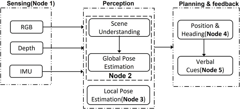
FIGURE 1. The navigation system contains several ROS nodes. Five different nodes are running on a Jetson machine simultaneously, and each node communicates through the message system provided by ROS. Sensing is one node. Perception has two nodes, and Planning and Feedback has two nodes.
2.2 Sensing Node
The sensing node streams RGB-D and IMU data to nodes. The size of RGB-D images is 848 × 480 at 60 Hz and IMU (acceleration and angular velocity) at 60 and 200 Hz, respectively. Two internal threads are assigned to stream data.
2.3 Perception—Scene Understanding
Semantic information (location of a crosswalk end plate) can provide a critical link between a saved prior map, collected with LiDAR (Light Detection and Ranging), and real-time RGB-D streaming data. Stability and reliability are important to the navigation system, thus relying only on raw and noisy depth data can lead to inaccuracy and poor performance. Further, semantic features can be a supplement for guidance and path planning, since a destination (a door, for example) can be labeled as a semantic feature on a map. Finally, this information is included in publicly available prior maps that are being created for autonomous vehicles. Therefore, designing a system that uses a prior map with semantic information increases performance and anticipates the availability of such information in autonomous systems infrastructure. We created a new architecture for scene understanding that balances prediction quality of segmentation with inference processing time, due to the requirement for real-time processing. We focus on fusing different scale resolution without degeneration of accuracy and real-time inference, based on Bisenet_v2 (Yu et al., 2020) and HarDNet (Chao et al., 2019). Bisenet has two pathways: semantic branch and detail branch. Taking two inputs can cause a bottleneck because of many operations at the initial layers. The network eventually reduces input resolution (512 × 1024) resulting in vulnerability to segment small objects. HarDNet architectures based on DenseNet (Iandola et al., 2014) resolved computational efficiency by a harmonic based constructions without accuracy penalty. Our architecture in Figure 2 manages a large size input (1,024 × 1,024) and understanding semantic features with double fusion from different branches. Inspired by the HardNet structure, the Concat blocks extract contextual information with understanding in different scales through the fusions into the main branch and the down branch by a modified U-net structure. Table 1 describes the details of network about input features size, the number of layers, and network parameters.
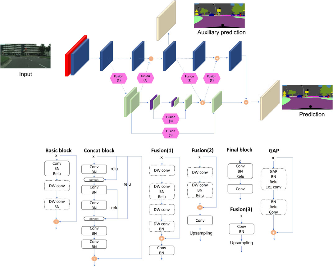
FIGURE 2. Network architecture. Each color block represents a different module and each module schematic is shown below the architecture diagram. Red—simple convolution layer; Blue—basic block; Green—concat block; Hexagon—up and down fusion; Purple—global average pooling; Beige—final and extra layer. DW conv, depthwise convolution. BN, batch normalization. Auxillary prediction is solely for training.
2.3.1 Dataset
To train and validate our network, we used two sources: online data sets (Cordts et al., 2016) and images acquired from 16 crosswalks near our research lab. Cityscapes is an open-source dataset of urban scenes that has a large image resolution (1,024 × 2,048) and contains 19 labels. This resolution is widely used by self-driving cars, but for wearable technology with less computing power, real-time image segmentation at this resolution is a challenge. The Cityscapes includes 2,975 annotated images used for training, 500 images for validation, and 1,525 images for test. This verified our network’s capability on a general dataset to ensure against overfitting. The custom training dataset was collected from 16 different crosswalks including four labels (crosswalks, texture plates, “safe-to-cross,” and “do-not-cross”). From this custom dataset, the total number of seed images is 4,541.
2.3.2 Training
The number of epochs is 800 and Stochastic gradient descent (SGD) is used with the initial learning rate 0.01, momentum of 0.9, and weight decay of 0.000 5. SGD method was used because, compared to Adam, SGD can escape from local minima and converge to a flatter basin indicating a more generalized region (Zhou et al. 2020). The poly learning policy was used with power of 0.9 to decrease the learning rate and data augmentation adopted with random scaling from 0.5 to 1.6 in 0.1 resolution, random horizontal flip, and brightness change for the Cityscapes dataset. Meanwhile random brightness, translation, and rotation augmentation are applied to the custom crosswalks dataset. The input image is resized as 1,024 × 1,024. The batch size was 5 for each graphic card and syncBN was utilized. The loss was online hard example mining (OHEM) (Shrivastava et al., 2016).
2.4 Perception—Global Pose Estimation
There are two types of localization in the navigation system: one is global position in a prior map and the other is local pose estimation relative to the first frame. Finding initial global pose in a prior map is associated with crossing a street safely and efficiently, since the user must be pointed in the proper direction for the camera to detect the crosswalk signal. The global position indicates the current location of users on the prior map.
2.4.1 Prior Map
Prior maps are essential for self-driving vehicles to accurately position themselves in 3D space and support decision-making. Such prior maps are built by a Light Detection and Ranging (LIDAR) with corresponding RGB camera frames for detailed image features. The prior map we generated for our system includes geometric information, the intensity of each point, normal vectors, landmarks, and other sensor data such as magnetic field value. This information is similar to maps used by modern self-driving cars. Point cloud maps were generated by a hand-held Velodyne-32E(Lidar). The registered 3D point cloud is made by Fast slam (Montemerlo et al., 2002), loop closure detection, optimization, and filters which are built-in functions in the Velo-Viewer. Different modalities (LIDAR and RGB) to collect map data must be co-registered to make the system practical. With 2D—3D matching problem, semantic features can resolve issues related to insufficient camera capability. Figures 3, 4 are the prior maps used during the experiments; specifically, Figure 4A was utilized. The global pose is evaluated for each particle that is sampled on a prior map based on the result of scene understanding (Figure 5). Each particle has 6 degrees of freedom of pose (x, y, z, roll, pitch, yaw) and sampled visible point cloud within the viewing frustum from the prior map. Several projections of point cloud images (from the prior map) are compared with the predictions of segmentation network from the scene understanding node via mean Intersection of Union (mIOU) metric. The mean of filtered particles poses will be selected as the estimate of the user’s global position on the prior map.
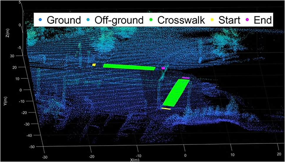
FIGURE 3. The prior map is annotated with semantic information with matched points. “Start” and “End” are texture plates which are helpful to visually impaired people providing tactile information. It can be reversed depending on direction of crossing.
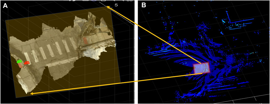
FIGURE 4. Example of point cloud at our test intersection. (B) is registered point cloud obtained with a lidar sensor. (A) is a registered point cloud by a ZED stereo camera. Overlaying these two points clouds provides a prior map with the accuracy of lidar and the color image information of RGB-D.
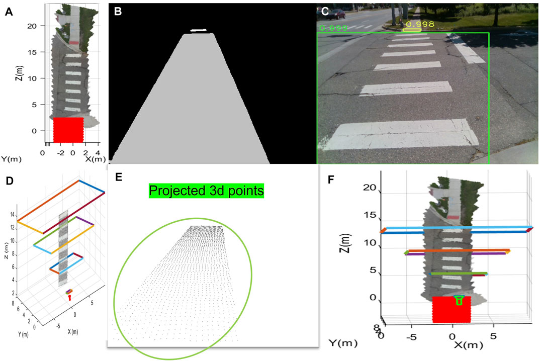
FIGURE 5. The figure shows the process of global pose estimation. (A) means sampled particles, (B) is the segmentation results, and (C) shows the actual image and how it was segmented. (D) is an example of the frustum of a particle (a possible pose for the user). (E) is the corresponding projected image for that pose. (F) shows the estimated pose on the prior map as the green camera symbol.
2.5 Perception—Local Pose Estimation
Local pose means the relative location from the first frame after global pose estimation is complete. We use local pose estimation as an alternative to evaluating global pose because particle-based global pose optimization in real-time is computationally expensive. After global location is evaluated while waiting for the “safe-to-cross” signal, the local pose is integrated to the global location. The local pose estimation is based on ORB-SLAM2 (Mur-Artal and Tardós, 2017). For real-time processing, feature-based ORB-SLAM2 is utilized in the system (Figure 6). Our SLAM adds semantic information of features in an additional thread. The original ORB-SLAM2 has three different threads to process the local mapping, tracking, and global pose optimization. The additional thread matches predicted semantic information to each key feature. The semantic information helps remove outliers of feature matching, weighted to reliable feature matching, and path planning. Eq. 1 is for pose optimization and to estimate landmarks (features).
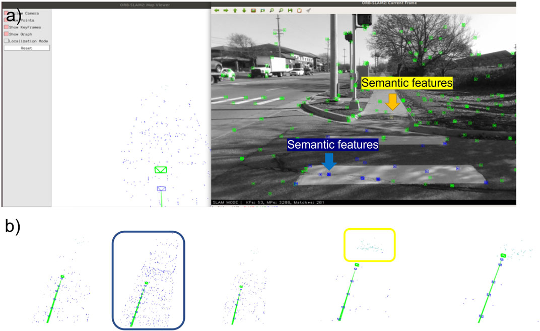
FIGURE 6. The figure shows semantic associated features in different colors. The blue dots mean crosswalk and the yellow is target destination (texture plates). The green dots are keypoints not associated with semantic information. The green dots in panel (A) are keypoints not associated with semantic information. Panel (B) is zoomed view of trajectory. The small blue rectangles are earlier keyframes, and the green small rectangle means current estimated camera pose.
The Σ is a covariance matrix indicating each pair’s uncertainty. The semantic information for the network can reduce or enhance the uncertainty if each pair has same labels with probability from the deep network.
2.6 Planning and Feedback—Position and Heading
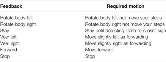
Path planning provides suitable feedback to users. Aligning the users toward target destination can significantly increase the success of street crossing. The system guides users to align correctly from the segmented results, based on the end side edges of crosswalks. It can help to detect a crosswalk sign in a scene because crosswalk signs are near to crosswalks. While waiting for the “safe-to-cross” sign, the system guided the participant to “stay” if alignment is correct (within ± 13°) or “rotate body left/right” if alignment is incorrect. When the system detects a “safe-to-cross” signal, the system instructs the participant to move “forward.” As long as the participant stays on the correct path, the system repeats “forward” every 5 s. Deviation from the path by more than 18° that is variable with the distance toward the texture plate or outside the crosswalk stripes triggers a “veer left/right” command, which is repeated every 5 s until the path is corrected. The table shows the types of feedback and expected motion. Obstacles such as pedestrians and riders are disregarded from the current navigation system so that the path planning focuses on heading and distance of trajectory.
2.7 Planning and Feedback—Verbal Cues
The guidance cues (Table 2) are transferred via bone conduction headphones, since over the ear or in-ear headphones would block the user’s hearing and BVI utilize hearing to understand their surroundings. Each cue has time interval of about 4 s to avoid confusion from frequently repeated feedback except for “rotate body left” and “rotate body right.”
2.8 Hardware Configuration
The hardware consists of Intel Realsense D435i camera, a Compass Sensor (BNO055 Bosch), a Jetson Xavier AGX, and a prior map (as described above). The user wears a headband with the camera mounted on it and holds a small bag to carry a Jetson computer and battery. The total weight of the device is about 5.5 lbs. Figure 7 shows how a user wears the system.
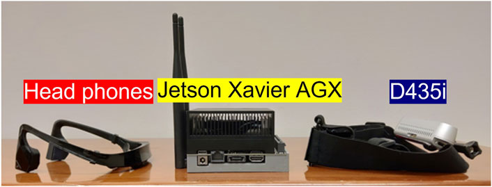
FIGURE 7. A test participant with the wearable system. The yellow region is a bag carrying a Jetson Computer and battery. The blue region is head-mounted camera, and the red means a bone-conducted headphone.
2.9 Human Participants Experiments
The study was approved by the University of Michigan Institutional Review Board. Three participants with severe visual impairment (legally blind) consented to enroll in the study. The participants reported that they could not use their vision to see a crosswalk or guide their trajectory while walking. Training was done indoors in a large conference room. The participants wore the system and guiding cues were provided. The participants were trained on how to respond to “rotate” and “veer” cues. Training emphasized the need to avoid moving too abruptly, since in prior work overreacting to a guiding cue has led to oscillatory walking. All participants were experienced with long cane guided walking. Once trained, experimenters led the participant to the crosswalk texture plate and aligned them so the crosswalk signal and zebra stripes were in the field of view of the camera. Real-time display of the headworn camera on a laptop allowed confirmation of the alignment. Once aligned, the experimenter was no longer in physical contact with the participant. For safety purposes, one of the experimenters walked aside and slightly behind the participant during the street crossing portion of the trial. If the participant veered too much from the crosswalk, the experimenter grabbed their arm and led them to the other side of the crosswalk. Video from the headworn camera and a hand-held camera recorded each trial. The guiding cues provided were logged and timestamped in data file. Participants were interviewed after the experiment to obtain their impressions of the system.
3 Results
We describe results in three parts: benchmarking our real time image segmentation network against state-of-the-art networks, system performance in detection and global localization, and testing in blind study participants.
3.1 Real Time Image Segmentation
To compare to other real-time segmentation networks for a practical scenario, we use a Net score (Wong, 2019) that is a common metric to analyze the performance of networks considering several factors. The score includes the number of parameters(γ), the number of multiply-accumulate (GMacs) (ρ) indicating the overall architectural and computational complexity, and mIOU(μ). We add FPS(θ) to the original Net score equation as another parameter because in practical scenarios with a mobile device, FPS can be important and the GMacs and the number of parameters are not correlated to FPS linearly. The κ, ϵ are 2 and β and α are set to 0.5 (Wong, 2019).
It can be modified, through adjusting exponents, to match the scenario to which the network is applied. We trained each network (except for Bisenet v2) on our desktop (Intel i5-6600k and 48 GB memory) to remove performance variation due to library version, cpu, gpu, and training strategy with Pytorch 1.8.0, Cuda 11.1, and 2 Geforce 1,080 gpus. On top of that, an extra dataset was not used to compare only architecture’s leverage even though the original networks basically used additional dataset such as Mapillary (Neuhold et al., 2017) or ImageNet (Deng et al., 2009). Table 3 indicates our network is slightly superior in the Net score even though each network shows higher performance in the individual metrics.

TABLE 3. The compared networks are high ranked in the Cityscape real-time benchmark. The mIOU results are with validation dataset. The FPS of Bisenet_v2 is on a 1,080 ti but our network is on a 1,080 which has less powerful resources than a 1,080 ti. Ours v2 is described in the Supplementary Material.
3.2 System Verification
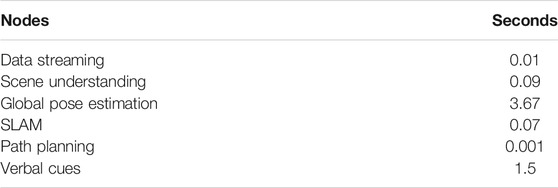
The Ddrnet_23_slim is ranked first in the Cityscapes web page. It shows the fastest FPS even though the number of parameters and the GMacs are not fewest. The HardNet’s highest resolution is 256 × 256 resulting in slower FPS to process multiplication internally compared to other networks. The number of parameters of Bisenet_v2 is unmentioned in the paper and the model is relatively outdated so implementation was not conducted. However, we included Bisenet_v2 in Table 3 since it was ranked at the first in real-time segmentation before the Ddrnet_23_slim emerged and several proposed networks that are high ranked are based on the Bisenet_v2. The system uses our network (labeled Ours in the table) due to the network balance for this scenario. Ours v2 shows the highest quality of segmentation and the details of its implementation are in the supplementary material. The system was verified at crosswalks before BVI participant experiments, to investigate its robustness, stability, and suitability to the crosswalk scenario. Four different crosswalks are visualized in Figure 3. Table 4 describes the results of initial global pose estimation with the prior map and classification of signs. The acceptable criteria is mentioned in Section 3.2. The number of classifications per frames is not counted because the important metric is the detection of the crosswalk signal as it changes to “safe-to-cross” symbol. The trials were performed through 2=months and variable day time. The failure of initial pose estimation was caused due to ambiguity of 2D and 3D matching. Table 4 reports processing time of each node.

TABLE 4. Four different crosswalks were used to test the system. Each trial had different start position and heading on texture plates.
3.3 Crossing Tests
All three study participants completed the study. Each separate crossing was considered a trial. We define a successful trial as when the participant (1) begins crossing the street with “safe-to-cross” signal and (2) reaches the final destination (near the texture plate) without assistance from the experimenters. Successful initial global pose estimation was defined as within 80 cm radius of ground truth. The individuals’ walking speed is estimated from recorded videos based on the shortest path to cross the street from the center of start plates and to center of end destination, which is 14.57 m measured by google map distance. Results from the crosswalk trial are summarized in Table 5 and exemplary crosswalk trial trajectories are shown in Figure 9. S009 and S010 successfully completed 6/6 trials, so we stopped testing at this point, since these participants demonstrated their ability to use the system. S008 had two failed trials. In one case, the local pose estimation failed while the participant was in the crosswalk due to interruption by a moving object (a car). The obstacle blocked a large portion of the camera field of view causing loss of landmarks used by SLAM and inaccurate localization. In the second failed trial, the participant responded incorrectly to “veer left” by veering right instead. An experimenter directed her to the end of the crosswalk. Both of these failures occurred within the first four trials. She successfully completed her last four trials. We added two additional trials for this participant (vs. S009 and S010) due to the failed trials. PPWS was obtained by dividing their speed walking during the crosswalk trial by their preferred walking speed, which we measured indoors after the crosswalk testing.

TABLE 5. C1 and C2 mean the different crosswalk. IP means initial pose estimation. C is success of classification of signs. The PPWS is the percentage preferred walking speed of mean of trials. IV is the number of intervention in the entire tests by assistants. The ICR indicates the number of incorrect responses by users.
3.4 Visualization of Trajectory
We roughly aligned participants initially and this resulted in incorrect initial headings in 5, 4, 3 times for participant s008, s009, s010, respectively. Figure 8 shows an example of user response when feedback related to aligning based on segmentation results is provided. The left two images in Figure 9 are results of S010. The two in the middle of Figure 9 are results of S009 and the last two are from S008. The first trial was failed due to incorrect responses. Each annotated feedback is essential motion to get to the destination. The pink triangle is approximated initial orientation and location on the start plate. The misalignment of trajectory and the triangle is intended. With guidance cues for correct alignment, the individuals could begin their crossing. The red circles mean individual incorrect responses of individuals and the blue indicates corrected responses. After testing, we interviewed the participants to get their impressions of the system. All three agreed that the system did not require significant mental effort to use. Two of the three agreed that verbal instructions were easy to understand. All participants thought that a system like this would help them cross a street more safely.

FIGURE 8. Point of view from head mounted camera while the user waits to for the “safe-to-cross” signal. (A) is when the user was aligned incorrectly. (B) is the result of reaction from “rotate body left.” (C) is when they were properly aligned.
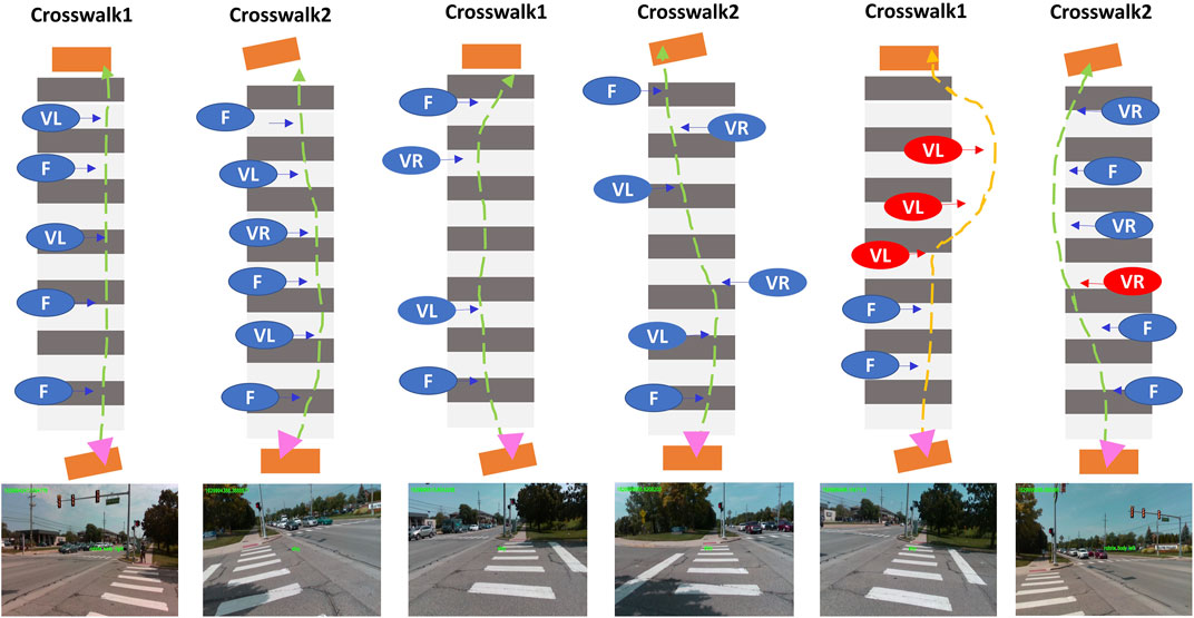
FIGURE 9. Visualized sampled and simplified results of participants. Two different crosswalks are symbolized and two of each are assigned to each subject in order of S010, S009, and S008.
4 Discussion
We validated a complete system for guiding crosswalk navigation in people with severe visual impairment. Our system localizes a user on a prior map and aligns them correctly towards the other end of the crosswalk. The signal state is classified and once “safe-to-cross” is detected, the user follows verbal commands to safely cross the street. Three blind test participants demonstrated the ease of use of the system at a real crosswalk. Other crosswalk systems only aided part of the process by detecting stripes or detecting the signal. Thus, our system, validated in blind participants, advances the state of the art.
We use off-the-shelf hardware to create the system. While still mobile, the system is not yet at the stage of a feasible product, due its size and weight. Advances in extended reality headsets provide a technology road map that can support similar functionality in robust commercial platform. Direct connection via wireless to the emerging transportation infrastructure may allow the system to off-load some tasks to computational resources that will be placed at intersections to manage auto traffic. For example, an intersection management system can provide the crosswalk signal status directly to the wearable system, eliminating the need for detection algorithms on the wearable hardware. We used a prior map which significantly improves localization. A system design that assumes availability of prior maps is reasonable given the up-to-date maps that will support autonomous systems. These maps include semantic labels. This means that such maps do not need to be created solely to support our navigation system.
For guiding cues, we focused on a method to significantly reduce the user requirement of active participation and mental fatigue while using the system. Assistive technology for BVI wayfinding includes some systems that can detect objects or patterns, but do not perform scene understanding. Brainport is a sensory substitution system that converts camera data into a pattern of electrical stimulation applied to the tongue. Mobility tests with Brainport showed an inordinate amount of time to navigate a hallway (Grant et al., 2016). In contrast, our system uses easily understood commands, and the users were able to maintain their preferred walking speed while crossing the street, which indicates that they were not slowed by decision making on how to respond. “Sunu band” is a smart band that can make users aware of obstacles on their path using a sonar sensor up to 5.5 m away. While this is helpful to avoid collisions, the user is still required to actively interpret this sparse information to understand their situation and how they should respond.
Our system used a simple approach to path planning because the desired route was a straight line and we disregarded dynamic objects. More sophisticated path planning algorithms, such as A∗ (Hart et al., 1968; Stentz, 1997), Dynamic Window Approach (Fox et al., 1997), and Reinforcement learning based planning (Wang et al., 2020), are examples of path planning algorithms that can improve the performance. A network bottleneck occurs at initial global pose estimation (Table 6). Each particle estimation takes about 0.004 s but we used about 891 particles, resulting in global post estimation requiring 3–4 s. While this time can be reduced by using fewer particles, it comes at the cost of reduced accuracy. We solve this problem by only performing global pose estimation at the beginning of our process while the user is waiting at the crosswalk starting point. However, global pose optimization in real-time (Levinson et al., 2007; Li et al., 2016) can be helpful in re-localization situation. It can reduce inevitable drift error of SLAM algorithms or it can replace SLAM.
During the experiments, the participants were satisfied with their performance using the navigation system. They were guided with simple cues without curtailing their preferred walking speed. The training for each command consumed about 10 min and the participants quickly learned the proper amount of movement for each command. However, S008 failed two cases. The first failure case was due to broken SLAM system caused by features occlusion. The current navigation system is based on relative poses from SLAM. It can be unstable when tracked features are changed or occluded by moving obstacles. To address this problem, global position based on real-time mapping and estimation is required with understanding and predicting other objects’ motion. The other failure case was resulted from S008 reacting incorrectly to verbal cues. The system provided “veer left” but S008 continuously moved to the right. It can be possible because the outdoors is usually noisy and distracting. The combination of vibrotactile and verbal feedback may diminish the confusion.
In our experiments, we guided the participants to the crosswalk texture plate and aligned them towards the crosswalk. Eventually, the system will need additional capability to provide this guidance. A combination of GPS and compass information can provide adequate pose estimation to allow the system to align the user towards the start of the crosswalk such that the camera and network can detect the crosswalk starting point and guide the user to this point. To simulate GPS/Compass, our prototype included a magnetic sensor for alignment and an Aptiltag (Olson, 2011) detector to simulate GPS. However, when we tested this function on ourselves, the requirement for magnetic sensor calibration was judged to be too demanding for participants. Therefore, this part of the system was not evaluated by BVI participants. Global orientation evaluation must be considered to navigate in the real world. The drift error of relative localization can cause incorrect feedback generation when long travelling is required. Improving depth perception and real-time global position estimation on a prior map can be a suitable strategy to avoid accumulated errors in localization. We are focusing on 3-D global localization with improved depth inference and decreased inference time on mobile device to expand their independent travelling range. The current navigation system does not consider moving obstacles, which must be added to future versions of the system for more reliable path planning.
We propose a new navigation system dealing with different modality problems using semantic information and anticipating integration with smart transportation infrastructure. To be useful, such a system must be easy to use. We demonstrate that simple verbal commands can effectively convey guidance instructions, but that other sensory inputs, like vibration, may be needed to ensure against critical mistakes by the user. Emerging wearable technology will allow implementation of our system on a practical, robust system, to allow realization of useful wayfinding technology for people with visual impairment.
Data Availability Statement
The raw data supporting the conclusion of this article will be made available by the authors, without undue reservation.
Ethics Statement
The studies involving human participants were reviewed and approved by the institutional review board of the University of Michigan. The patients/participants provided their written informed consent to participate in this study.
Author Contributions
HJ wrote the software, designed the system, designed the experiments, recorded data during experiments, analyzed data, and wrote the manuscript. JW designed the experiments, recruited the participants, conducted experiments, and wrote the manuscript.
Funding
This work was supported by the University of Michigan. Support for this project was provided by the University of Michigan and the Kellogg Vision Research Core funded by P30 EY007003 from the National Eye Institute.
Conflict of Interest
The authors declare that the research was conducted in the absence of any commercial or financial relationships that could be construed as a potential conflict of interest.
Publisher’s Note
All claims expressed in this article are solely those of the authors and do not necessarily represent those of their affiliated organizations, or those of the publisher, the editors, and the reviewers. Any product that may be evaluated in this article, or claim that may be made by its manufacturer, is not guaranteed or endorsed by the publisher.
Acknowledgments
Thanks to Dorsa Haji-Ghaffari, Kate Kish, and Negin Nadvar for their assistance with the human experiments.
Supplementary Material
The Supplementary Material for this article can be found online at: https://www.frontiersin.org/articles/10.3389/felec.2021.790081/full#supplementary-material
References
Ackland, P., Resnikoff, S., and Bourne, R. (2017). World Blindness and Visual Impairment: Despite many Successes, the Problem Is Growing. Community eye health 30, 71–73.
Adebiyi, A., Sorrentino, P., Bohlool, S., Zhang, C., Arditti, M., Goodrich, G., et al. (2017). Assessment of Feedback Modalities for Wearable Visual Aids in Blind Mobility. PloS one 12, e0170531. doi:10.1371/journal.pone.0170531
Bibby, S. A., Maslin, E. R., McIlraith, R., and Soong, G. P. (2007). Vision and Self‐reported Mobility Performance in Patients with Low Vision. Clin. Exp. Optom. 90, 115–123. doi:10.1111/j.1444-0938.2007.00120.x
Bourne, R. R., Adelson, J., Flaxman, S., Briant, P., Bottone, M., Vos, T., et al. (2020). Global Prevalence of Blindness and Distance and Near Vision Impairment in 2020: Progress towards the Vision 2020 Targets and what the Future Holds. Invest. Ophthalmol. Vis. Sci. 61, 2317.
Chao, P., Kao, C.-Y., Ruan, Y.-S., Huang, C.-H., and Lin, Y.-L. (2019). Hardnet: A Low Memory Traffic Network. In Proceedings of the IEEE/CVF International Conference on Computer Vision. 3552–3561. doi:10.1109/iccv.2019.00365
Cordts, M., Omran, M., Ramos, S., Rehfeld, T., Enzweiler, M., Benenson, R., et al. (2016). The Cityscapes Dataset for Semantic Urban Scene Understanding. In Proceedings of the IEEE conference on computer vision and pattern recognition. 3213–3223. doi:10.1109/cvpr.2016.350
Coughlan, J. M., and Shen, H. (2013). Crosswatch: a System for Providing Guidance to Visually Impaired Travelers at Traffic Intersection. J. assistive Tech. doi:10.1108/17549451311328808
Deng, J., Dong, W., Socher, R., Li, L.-J., Li, K., and Fei-Fei, L. (2009).Imagenet: A Large-Scale Hierarchical Image Database. In IEEE conference on computer vision and pattern recognition. IEEE, 248–255. doi:10.1109/cvpr.2009.5206848
Duncan, J. L., Richards, T. P., Arditi, A., da Cruz, L., Dagnelie, G., Dorn, J. D., et al. (2017). Improvements in Vision‐related Quality of Life in Blind Patients Implanted with the Argus II Epiretinal Prosthesis. Clin. Exp. Optom. 100, 144–150. doi:10.1111/cxo.12444
Fox, D., Burgard, W., and Thrun, S. (1997). The Dynamic Window Approach to Collision Avoidance. IEEE Robot. Automat. Mag. 4, 23–33. doi:10.1109/100.580977
Grant, P., Spencer, L., Arnoldussen, A., Hogle, R., Nau, A., Szlyk, J., et al. (2016). The Functional Performance of the Brainport V100 Device in Persons Who Are Profoundly Blind. J. Vis. Impairment Blindness 110, 77–88. doi:10.1177/0145482x1611000202
Hart, P., Nilsson, N., and Raphael, B. (1968). A Formal Basis for the Heuristic Determination of Minimum Cost Paths. IEEE Trans. Syst. Sci. Cyber. 4, 100–107. doi:10.1109/tssc.1968.300136
Iandola, F., Moskewicz, M., Karayev, S., Girshick, R., Darrell, T., and Keutzer, K. (2014). Densenet: Implementing Efficient Convnet Descriptor Pyramids. arXiv preprint arXiv:1404.1869.
Kuriakose, B., Shrestha, R., and Sandnes, F. E. (2020). Tools and Technologies for Blind and Visually Impaired Navigation Support: A Review. IETE Tech. Rev., 1–16. doi:10.1080/02564602.2020.1819893
Lamoureux, E., and Pesudovs, K. (2011). Vision-specific Quality-Of-Life Research: a Need to Improve the Quality. Am. J. Ophthalmol. 151, 195–197. doi:10.1016/j.ajo.2010.09.020
Lange, R., Kumagai, A., Weiss, S., Zaffke, K. B., Day, S., Wicker, D., et al. (2021). Vision-related Quality of Life in Adults with Severe Peripheral Vision Loss: a Qualitative Interview Study. J. Patient Rep. Outcomes 5, 7–12. doi:10.1186/s41687-020-00281-y
Lee, Y. H., and Medioni, G. (2011). “Rgb-d Camera Based Navigation for the Visually Impaired,” in Proceedings of the RSS (Citeseer), 2.
Levinson, J., Montemerlo, M., and Thrun, S. (2007). Map-based Precision Vehicle Localization in Urban Environments. Robotics: Sci. Syst. (Citeseer) 4, 1. doi:10.15607/rss.2007.iii.016
Li, L., Yang, M., Wang, C., and Wang, B. (2016).Road Dna Based Localization for Autonomous Vehicles. In 2016 IEEE Intelligent Vehicles Symposium (IV). IEEE, 883–888. doi:10.1109/ivs.2016.7535492
Li, B., Muñoz, J. P., Rong, X., Chen, Q., Xiao, J., Tian, Y., et al. (2018). Vision-based mobile Indoor Assistive Navigation Aid for Blind People. IEEE Trans. Mob Comput. 18, 702–714. doi:10.1109/TMC.2018.2842751
Li, X., Cui, H., Rizzo, J.-R., Wong, E., and Fang, Y. (2019). “Cross-safe: A Computer Vision-Based Approach to Make All Intersection-Related Pedestrian Signals Accessible for the Visually Impaired,” in Science and Information Conference (Springer), 132–146. doi:10.1007/978-3-030-17798-0_13
Lord, S. R., and Dayhew, J. (2001). Visual Risk Factors for Falls in Older People. J. Am. Geriatr. Soc. 49, 508–515. doi:10.1046/j.1532-5415.2001.49107.x
Marron, J. A., and Bailey, I. L. (1982). Visual Factors and Orientation-Mobility Performance. Optom. Vis. Sci. 59, 413–426. doi:10.1097/00006324-198205000-00009
Montemerlo, M., Thrun, S., Koller, D., and Wegbreit, B. (2002). FastSLAM: A Factored Solution to the Simultaneous Localization and Mapping Problem. Aaai/iaai, 593598.
Mur-Artal, R., and Tardós, J. D. (2017). Orb-slam2: An Open-Source Slam System for Monocular, Stereo, and Rgb-D Cameras. IEEE Trans. Robot. 33, 1255–1262. doi:10.1109/tro.2017.2705103
National Academies of Sciences, E., Medicine (2017). Making Eye Health a Population Health Imperative: Vision for Tomorrow. Washington, DC: National Academies Press.
Nau, A. C., Pintar, C., Arnoldussen, A., and Fisher, C. (2015). Acquisition of Visual Perception in Blind Adults Using the Brainport Artificial Vision Device. Am. J. Occup. Ther. 69, 6901290010p1–6901290010p8. doi:10.5014/ajot.2015.011809
Neuhold, G., Ollmann, T., Rota Bulo, S., and Kontschieder, P. (2017). The Mapillary Vistas Dataset for Semantic Understanding of Street Scenes. In Proceedings of the IEEE international conference on computer vision. 4990–4999 .
Olson, E. (2011).Apriltag: A Robust and Flexible Visual Fiducial System. In 2011 IEEE International Conference on Robotics and Automation. IEEE, 3400–3407.
Quigley, M., Conley, K., Gerkey, B., Faust, J., Foote, T., Leibs, J., et al. (2009). “Ros: an Open-Source Robot Operating System,” in ICRA Workshop on Open Source Software (Japan: Kobe), 3, 5.
Sato, D., Oh, U., Naito, K., Takagi, H., Kitani, K., and Asakawa, C. (2017). Navcog3: An Evaluation of a Smartphone-Based Blind Indoor Navigation Assistant with Semantic Features in a Large-Scale Environment. In Proceedings of the 19th International ACM SIGACCESS Conference on Computers and Accessibility. 270–279.
Shangguan, L., Yang, Z., Zhou, Z., Zheng, X., Wu, C., and Liu, Y. (2014). Crossnavi: Enabling Real-Time Crossroad Navigation for the Blind with Commodity Phones. In Proceedings of the 2014 ACM International Joint Conference on Pervasive and Ubiquitous Computing. 787–798.
Shrivastava, A., Gupta, A., and Girshick, R. (2016). Training Region-Based Object Detectors with Online Hard Example Mining. In Proceedings of the IEEE conference on computer vision and pattern recognition. 761–769 .
Son, H., Krishnagiri, D., Jeganathan, V. S., and Weiland, J. (2020).Crosswalk Guidance System for the Blind. Annu. Int. Conf. IEEE Eng. Med. Biol. Soc., 2020, 3327–3330. doi:10.1109/EMBC44109.2020.9176623
Stentz, A. (1997). “Optimal and Efficient Path Planning for Partially Known Environments,” in Intelligent Unmanned Ground Vehicles (Springer), 203–220. doi:10.1007/978-1-4615-6325-9_11
Wang, H.-C., Katzschmann, R. K., Teng, S., Araki, B., Giarré, L., and Rus, D. (2017).Enabling Independent Navigation for Visually Impaired People through a Wearable Vision-Based Feedback System. In 2017 IEEE international conference on robotics and automation (ICRA). IEEE, 6533–6540. doi:10.1109/icra.2017.7989772
Wang, B., Liu, Z., Li, Q., and Prorok, A. (2020). Mobile Robot Path Planning in Dynamic Environments through Globally Guided Reinforcement Learning. IEEE Robot. Autom. Lett. 5, 6932–6939. doi:10.1109/lra.2020.3026638
Wong, A. (2019). “Netscore: towards Universal Metrics for Large-Scale Performance Analysis of Deep Neural Networks for Practical On-Device Edge Usage,” in International Conference on Image Analysis and Recognition (Springer), 15–26. doi:10.1007/978-3-030-27272-2_2
Yu, C., Gao, C., Wang, J., Yu, G., Shen, C., and Sang, N. (2020). Bisenet V2: Bilateral Network with Guided Aggregation for Real-Time Semantic Segmentation. arXiv preprint arXiv:2004.02147.
Keywords: wearable system, human-machine interaction, independent travelling, wayfinding, visual impairment, image segmentation, AI for health care
Citation: Son H and Weiland J (2022) Wearable System to Guide Crosswalk Navigation for People With Visual Impairment. Front. Electron. 2:790081. doi: 10.3389/felec.2021.790081
Received: 06 October 2021; Accepted: 06 December 2021;
Published: 03 March 2022.
Edited by:
Yu Wu, University College London, United KingdomReviewed by:
Xuhang Chen, Beihang University, ChinaCheng-Kai Lu, University of Technology Petronas, Malaysia
Copyright © 2022 Son and Weiland. This is an open-access article distributed under the terms of the Creative Commons Attribution License (CC BY). The use, distribution or reproduction in other forums is permitted, provided the original author(s) and the copyright owner(s) are credited and that the original publication in this journal is cited, in accordance with accepted academic practice. No use, distribution or reproduction is permitted which does not comply with these terms.
*Correspondence: Hojun Son, aG9qdW5zb25AdW1pY2guZWR1
 Hojun Son
 James Weiland
