 Ali Ghadami
 Hamid Reza Mirdamadi2,3
 Hamideh Khanbareh
- 1Department of Mechanical Engineering, Sharif University of Technology, Tehran, Iran
- 2Department of Mechanical Engineering, Isfahan University of Technology, Isfahan, Iran
- 3Department of Control Engineering and System Analysis, Active Structures Lab, Universite Libre de Bruxelles, Brussels, Belgium
- 4Department of Mechanical Engineering, Materials and Structures Centre (MAST), University of Bath, Bath, United Kingdom
With recent advances in system integration technologies, numerous efforts have been made to develop soft piezoelectric sensors for various engineering and healthcare applications. Using flexible and sensitive materials is crucial for designing soft sensors in order to maximize their efficiency and integrability. Micro-porous PU-PZT composite is a recently designed piezoelectric particulate composite material with an improved flexibility and piezoelectric voltage coefficient over common piezoelectric ceramics that makes it a promising candidate for application in soft sensors. In this study, we investigate the dynamic response and sensitivity of the micro-porous PU-PZT composite for applications in soft sensors in both 33 and 31 modes using energy methods. By using the effective field method, the micro-porous PU-PZT composite material properties were extracted and optimized based on the partially experimentally measured properties in order to get a complete picture of the properties of the material. In addition, the effects of changing the sensor geometry by varying the thickness and adding an extra layer between the piezoelectric layers are studied. Finally, a large area sensor based on micro-porous PU-PZT composite is simulated in finite element software, and the effect of several parameters on sensor’s performance is investigated. Dynamic analysis of the sensor shows high sensitivity in both 31 and 33 modes which is a significant improvement compared to the commonly used bulk piezoelectric ceramics. This work has demonstrated that due to the high output voltage and structural flexibility of the micro-porous PU-PZT composite, a flexible large-area sensor would be a suitable choice for artificial skins and smart gloves.
1 Introduction
Piezoelectric materials are widely used in many applications as sensors and actuators due to their unique properties that generate electric charge in response to mechanical input and vice versa. Application of piezoelectric sensors ranges from pressure and vibration sensors (Chuang et al., 2008; Shih et al., 2017; Yaghootkar et al., 2017; Kim and Kim, 2018) to sensors applicable in minimally invasive surgery (Wang et al., 2011), monitoring human health (Yeo and Lim, 2016), and active vibration control (Biglar et al., 2014; Biglar and Mirdamadi, 2014; Biglar and Mirdamadi, 2016). Touch sensors and robotics applications have benefited greatly from piezoelectric sensors due to their durability, sensitivity, and affordability.
In particular, with the recent advances in soft robotics, piezoelectric sensors have become an inseparable part of the designed robots. Soft robotics is an evolving field and aims to design robots composed of soft and stretchable materials for applications, including handling delicate materials using soft grippers and safe human-robot interaction, which are not possible using traditional rigid robots. The solid-state sensors traditionally used in robotics cannot capture the high-dimensional deformation of soft systems (Thuruthel et al., 2019). Embedded soft sensors are an appropriate solution for this approach because they are thin, flexible, cover a large area like the human skin, and resist external forces and chemical pollution (Chuang et al., 2008). According to Dr. Mandayam A. Srinivasan, founder of the MIT Touch Lab, an ideal soft sensor “essentially has to be what skin is: flexible, with the ability to sense dynamically and with high spatial resolution, and physically robust—it shouldn’t break, it shouldn’t wear out.” (MIT Technology Review J, 2006).
Given that flexibility and sensitivity are two important factors affecting the functionality of the sensors, composite materials are promising candidates for fabricating a sensor that satisfies our needs. Composite piezoelectric materials are chosen because one can optimize their electrical and mechanical properties as desired for a particular application. In addition, properties that cannot be achieved by a single material can be achieved with composite materials. Due to the need for embedding sensors in flexible structures, the demands for soft sensors have been increased over recent years, and several approaches have been investigated to reach this flexibility. For instance, in a research performed by Kim et al. (2020), soft gloves with integrated piezoelectric sensors have been developed to estimate hand motion for human-machine interaction applications. A PVDF film was used as a sensor, and the sensor was fabricated with a uniform beam structure with thin PVDF and Mylar layers. The glove was fabricated using Ecoflex 00–30 silicone rubber. Finally, using deep learning, the motion of the hand was predicted with sensors output voltage and used in a virtual reality interface system. Using discrete hard PZT ceramics in a flexible substrate can be another way to reach flexibility in the sensor structure. Acer et al. (2015) presented a solution by embedding PZT elements in an elastic silicon substrate that provided enough flexibility and softness and could even be used as a wearable sensor for contact detection and force measurement.
Micro-porous PU-PZT composite is a novel soft piezoelectric sensor that was manufactured by dispersing PZT5A4 ceramic powders (mean particle size of 1.8 μm) in a dense polymeric matrix (Smooth-on-Econ 80 polyurethane) and adding a third phase (gaseous) to the system. The presence of gaseous pores not only increases the sensor’s flexibility, but also increases the piezoelectric voltage coefficient (g33) by decreasing the dielectric permittivity. A further improvement in d33 was achieved by dielectrophoresis (DEP), a process used to align piezoelectric particles and form long chains in an AC electric field, and an intermediate state between 0–3 and 1–3 connectivity was achieved. The g33 coefficient was measured to be 165 mV·m/N which is a significant improve from the bulk PZT and PU composites (Khanbareh et al., 2017; Ali and Hamideh, 2021).
In this study, we consider the recently developed micro-porous PU-PZT composite material in a modeled multilayer circular sensor. The comprehensive properties of the micro-porous PU-PZT composite material required for dynamic analysis of the sensor response in the mathematical and COMSOL® model will be estimated using the effective field method (Glushanin et al., 2006) and partially available experimental data. The sensor resolution of the skins is an essential factor that should be taken into account. Using soft tissues and soft sensory materials and leveraging robust algorithms like neural networks, it will be possible to reach high sensing resolutions with limited sensors. As bending plays an essential role in soft materials sensing, and it is not investigated for the aforementioned material, it will be specially considered in this work, as both 33 and 31 modes can affect the output significantly.
First, we compare the micro-porous PU-PZT composites to other common piezoelectric materials in 33 mode to show its improvements as mentioned in the main paper. The functionality of the micro-porous PU-PZT composite material will be also investigated in the 31 mode as this mode plays an important role in soft sensors. Notably, the flexibility of the sensor is essential for integrating the sensor within a system, and the micro-porous PU-PZT composite has the highest flexibility among common materials used in sensor design. In addition, the effect of the piezoelectric layer and middle layer thickness on the performance of the micro-porous PU-PZT composite sensor is of interest which is beneficial to find the optimum rigidity and functionality of this sensor for the desired application. In the next step, as we aim to design a large area flexible sensor, a more complicated model of this sensor is developed and analyzed in COMSOL®. This theoretical simulation could be an important step in the practical implementation of this sensor and system.
2 Materials and methods
In this section, the formulation and procedures used in this study are described in detail. First, the constitutive equations of the piezoelectric materials are provided, and the relationship for output voltage in the 33 mode is calculated. Then the circular bending 31 sensor system is developed using energy methods. Finally, an approach for predicting the properties of the particulate piezoelectric materials is proposed.
2.1 Piezoelectric constitutive equations in 33 mode
Piezoelectric materials are widely used as sensors or energy harvesters in their 33 mode, meaning that the sensor is under stress in the poling direction and the induced voltage is in the same direction. Thus, it is essential to evaluate their performance in this situation. Here, it is desired to model a simple sensor mathematically and review the constitutive equations of the piezoelectric materials.
The relationship between applied force, the displacement, and induced electrical charge can be described as (Leo, 2007):
where,
Considering open circuit condition, we can simply set V to zero,
Resulting in the output voltage as follows:
The term
2.2 Modeling a 31 bending piezoelectric sensor
In this section, we first derive an analytical solution for a circular laminated sensor composed of a piezoelectric material and investigate its performance under a dynamic excitation. In this mode, the sensor is under stress perpendicular to the poling direction and the induced voltage is in the poling direction. The relationship between applied force and output voltage as well as deflection will be evaluated. In addition, the resonant frequencies of the system are calculated.
2.2.1 Theory and hypothesis
We employ the classical plate theory (CPT) for the analyses (Reddy, 2017). Because only the small bending deformation of plates are considered, the displacement field in the absence of tension loads reduces to:
With this displacement field, for small displacements, the only nonzero stains are: (Reddy, 2017)
Here we analyze a non-piezoelectric layer in the middle, sandwiched between two piezoelectric layers and assumed to have a simply supported constraint at
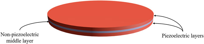
FIGURE 1. A schematic of the sensor studied in this work.
2.2.2 Dynamic 31 response
Given the material properties of the micro-porous PU-PZT composites, we aim to identify the relation between distributed dynamic load, deflection, induced voltage (sensor output), and resonant frequencies for the considered sensor geometry (as shown in Figure 1) and compare its dynamic response with sensors composed of other selected piezoelectric materials. According to the Classical Plate Theory (CPT) the effect of transverse normal stress is neglected and the output voltage is only dependent on the 31 mode. To perform a dynamic analysis on this system, we employ Hamilton’s principle as well as the Ritz method as bellow:
where
In these equations,
where
where “a” is the radius of the sensor,
The strain-displacement relationship with respect to CPT and for cylindrical coordinates are:
According to Eq. 8, one obtains:
where generalized coordinates are related to the strain vector. By this simplification, we can rewrite the terms for energy and work as follows:
Substituting Eq. 12 into the Hamilton principle and using proper shape functions, the governing equation for the system are obtained as follows,
and,
where M, k,
The eigenvalues of the matrix
It is notable that in the presence of the middle substrate, the output voltage is not simply proportional to a term which is purely related to material’s properties, like what we observed in 33 mode which was g33. In this case, for a static load, the output voltage would be described as follows:
where:
And
2.3 Prediction of effective properties of piezo-particulate composites
In order to evaluate the functionality of the sensors, it is critical to estimate the electrical and mechanical properties of the new material accurately. Here, we employ formulations developed based on the effective field method (Glushanin et al., 2006) to effectively estimate the mechanical and electrical properties of sensors composed of composite materials. This part aims to estimate piezo-particulate composites’ electrical and mechanical properties.
There are several approaches to predict piezo-particulate composite properties. In this work, we use the results of a micromechanics approach known as the Mori-Tanaka mean-field theory (Khanbareh et al., 2019). Consider a composite material composed of particles with 0–3 connectivity (single isolated inclusions) surrounded by a matrix. It is assumed that the shape of inclusions in Cartesian coordinates is described as follows:
where aspect ratio of the piezoelectric particles can be defined as
where
Based on the effective field method, the matrix
where superscript (1) denotes properties for piezo particles and superscript (2) corresponds to polymer properties. m is the volume fraction of piezoelectric particles, and S contains the electrostatic Eshelby tensor components. Assuming matrix S is known, we can calculate the composite’s effective properties using Eq. 19. Matrix S was explicitly defined by Huang with nine independent components as following: (Huang and Kuo, 1996)
Note that this matrix is dependent solely on the properties of the composite’s matrix (i.e., electromechanical properties) and the aspect ratio of particles. The particles are uniformly poled along the
3 Results
The purpose of this section is to make use of the formulations provided before to evaluate the performance of recently developed micro-porous PU-PZT composite as a candidate for designing large area soft sensors and compare it to commonly used piezoelectric materials. Further investigations are done in COMSOL®, and a closer model to a large area sensor is provided.
3.1 Property estimation
Performing the property estimation is essential for analyzing the system dynamics proposed in the following sections, and the effective field method was reviewed and implemented. As we need complete properties of the micro-porous piezoelectric material to evaluate its functionality and it is not feasible to find all of them using experiments, we can use properties of PZT5A4 and polyurethane separately to estimate the full properties of composite with the procedure described in the previous section using the Mori-Tanaka mean-field theory. Here, the aspect ratio of the particles is a tuning parameter and can be found by fitting the
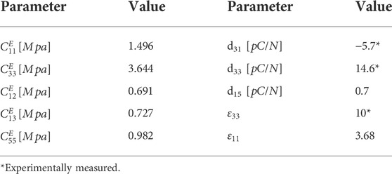
TABLE 1. Properties of the micro-porous PU-PZT composite.
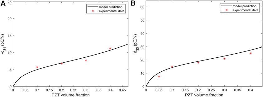
FIGURE 2. Diagrams of piezoelectric charge coefficient estimations. (A) Estimation of d31 with the tuned value of ρ, (B) Estimation of d33 with the tuned value of
3.2 Evaluation of micro-porous PU-PZT-based sensor in 33 mode
According to the formulations, the piezoelectric voltage constant (
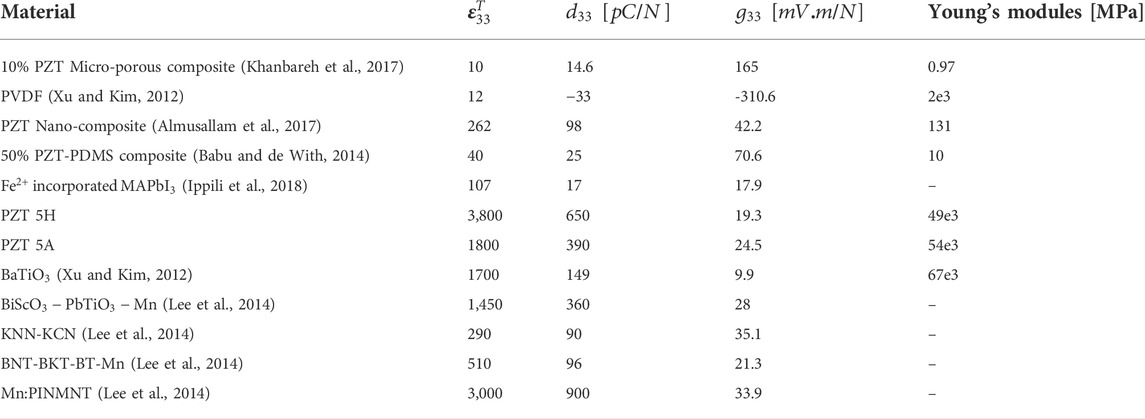
TABLE 2. A comparison of piezoelectric materials in 33 mode.
Results show that the PZT micro-porous composite material has a high
3.3 Evaluation of micro-porous PU-PZT-based sensor in 31 mode
Analysing the bending mode, which activates 31 mode of the sensor, is an essential step for designing piezoelectric sensors and actuators. In this section, the behaviour of a sensor under the bending forces is studied to evaluate the efficiency of PZT micro-porous material compared to the other commonly used materials in fabricating sensors. We use the model developed in Section 2 and analyze the micro-porous PU-PZT composites. First, the system’s output is calculated, and the structure’s resonant frequency is obtained and compared to other materials. Further, the changes in the structure, such as the sensor’s thickness, diameter, and the effect of an extra middle layer on the response are investigated.
3.3.1 Sensor’s output and resonant frequencies
To perform simulations, we have considered sensors to have a diameter of 2 cm and a thickness of 0.5 mm for each layer (As Figure 1). The maximum output voltage of the sensors (each layer) is calculated using the obtained transfer functions and under harmonic pressure of 2 kPa and frequency of 20 Hz. The first fundamental frequency of the system, which is essential in many applications, is also identified for the system. The results of this analysis are shown in Table 3; Figure 3. We observe that while the output voltage of the micro-porous PU-PZT composite is not the highest, it is a good improvement from the bulk PZT-5A. Also, we have a lower fundamental resonant frequency compared to other materials, which can be beneficial when designing a resonator or energy harvester using this material. The high value of g31, on the other hand, shows its unique performance when it is used as a bending beam or with stretching forces. Note that the flexibility of the sensor plays a vital role in integrating any system with that, and the micro-porous PU-PZT composite has the highest flexibility among all listed sensors. The results are also validated using COMSOL®. Besides the 31 mode voltage that is calculated based on previously presented transfer functions in Eq. 15, the 33 mode output voltage is calculated by substituting maximum stress in each layer in the Eq. 3. So, the total output voltage will be the summation of the 31 and 33 voltages with respect to their sign. Due to the stress concentration in the edges, there will be a very high compression stresses in order of roughly 15 times greater than the applied pressure that is not considered in theory. Thus, the COMSOL® output voltage result for 33 mode will be much larger than theory, and its results is not provided.
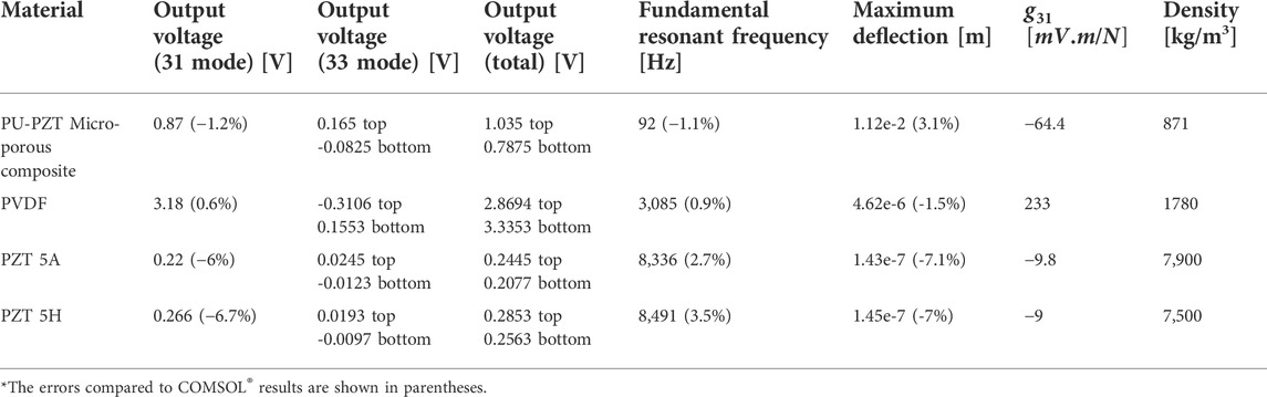
TABLE 3. A comparison of piezoelectric materials in 31 mode.
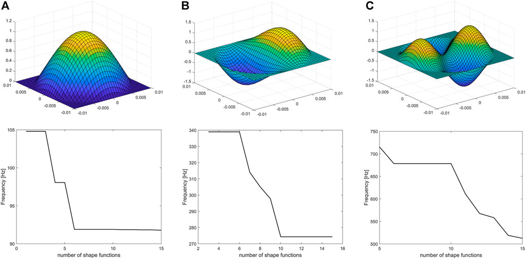
FIGURE 3. The first three bending mode shapes of the system and the convergence plot of their corresponding natural frequencies based on the number of shape functions considered [ω (i, j) is mode shape with radial mode number “i” and circular mode number “j”]. (A) 1st mode = ω(0,1) with resonant frequency of 92 Hz, (B) 2nd mode = ω(1,1) with resonant frequency of 274 Hz, (C) 3rd mode = ω(2,1) with resonant frequency of 512 Hz.
Other mode shapes of the system can be obtained using the developed formulations. For example, for the same configuration of the micro-porous PU-PZT composite, the results are shown in Figure 3.
Since the Ritz method is used, the convergence of the resonant frequencies depends on the number of considered shape functions. The effect of the number of shape functions on the solution is also investigated and provided in Figure 3. It is observed that the first resonant frequency converges after adding the 6th shape function, the second resonant frequency converges after adding the 10th shape function, and the convergence of third frequency demands inclusion of more than 15 shape functions in the calculations. Hence, if the values of the higher resonant frequencies are needed, one should use more shape functions for an accurate result.
3.3.2 Effects of structural parameters on sensor response
Parameters like the sensor’s diameter, thickness, and presence of an extra middle layer can affect the sensor’s output voltage and resonant frequency. So, in this part, the effects of these parameters in our 31 system with micro-porous PU-PZT composite material is investigated and the results are provided in Figures 4, 5, 6.
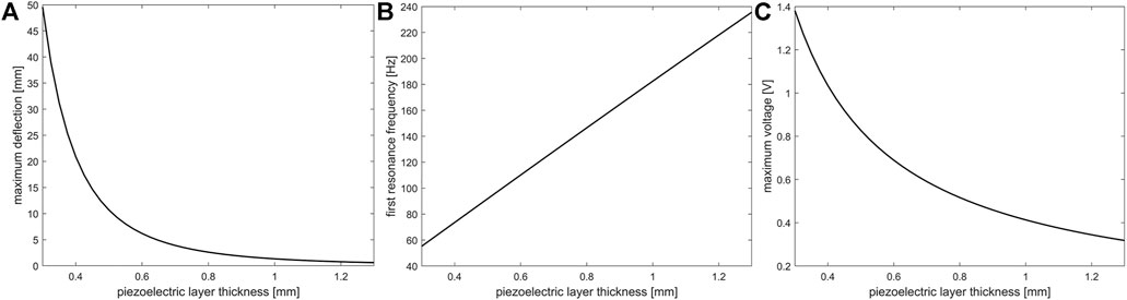
FIGURE 4. The effect of micro-porous PU-PZT composite layer thickness on the (A) maximum deflection, (B) first resonant frequency, and (C) on output voltage of the sensor. These studies were done with a dynamic load of 2 kPa and 3 Hz with a constant radius of 1 cm.
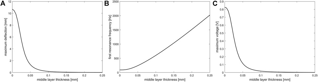
FIGURE 5. The effect of middle (metal) layer thickness on the (A) maximum deflection, (B) first resonant frequency, and (C) on output voltage of the sensor. These studies were done with a dynamic load of 2 kPa and 3 Hz with a constant radius of 1 cm and piezoelectric thickness of 0.5 mm. Here middle layer is aluminum.
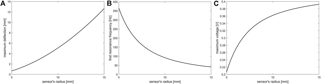
FIGURE 6. The effect of sensor’s radius on the (A) maximum deflection, (B) first resonant frequency, and (C) on output voltage. These studies were done with a dynamic load of 2 kPa (on a constant area) and 3 Hz and piezoelectric thickness of 0.5 mm.
According to the results, by increasing the piezoelectric layer thickness, the maximum deflection of the sensor and the output voltage decreases, but the resonant frequency increases linearly. The same trend is observed when an extra layer is added between piezoelectric layers, but in this case, changes will occur with higher intensity, and the variation of resonant frequency increase is not linear. By increasing the sensor diameter while keeping the applied pressure constant, the maximum deflection and output voltage are increased while the resonant frequency is decreased nonlinearly. It is notable that in all of the simulations, the dynamic load was fully distributed on the surface. When the effect of radius was investigated, the area where the load was applied on that was constant to have constant total force.
The radial and circumferential stresses in the layers can be written as: (Reddy, 2017):
where
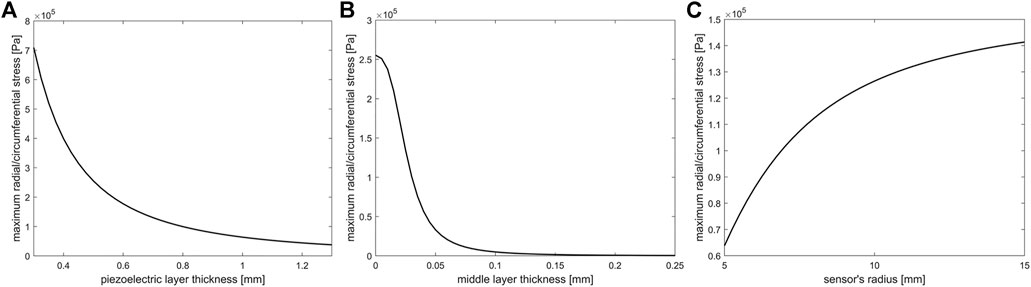
FIGURE 7. Effect of (A) piezoelectric layer thickness, (B) middle layer thickness, and (C) sensor’s radius on the maximum radial/circumferential stress.
The material of the middle layer can vary in different applications. Here, the effect of the young’s modulus of the middle layer (when the middle layer material is isotropic) is discovered and shown in Figure 8. The results show the same trend as what was observed before, but for materials with higher young’s modulus, the speed of changes increases dramatically.
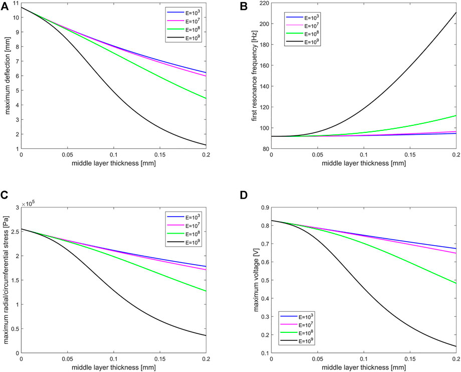
FIGURE 8. Effect of middle layer thickness with different young’s modulus on (A) maximum deflection, (B) first resonant frequency, (C) maximum radial/circumferential stress, and (D) maximum voltage. These studies were done with a dynamic load of 2 kPa and 3 Hz with a constant radius of 1 cm and piezoelectric thickness of 0.5 mm. Additionally, the unit of young’s modulus is Pa.
3.4 Micro-porous PU-PZT composite as a large area soft sensor
As discussed and analyzed above, the flexibility of the micro-porous composite enables the usage of this material as a large area sensor in many applications, including artificial soft skins. This feature encouraged us to propose and analyze a large area sensor in COMSOL® for further investigations. This sensor comprises a bottom layer of micro-porous PU-PZT composite and discrete circular electrodes on the top surface of that. A thin layer of PDMS is placed on the whole set for a better sense of touch, protection, and isolation of the electrodes. The schematic of the sensor is shown in Figure 9.
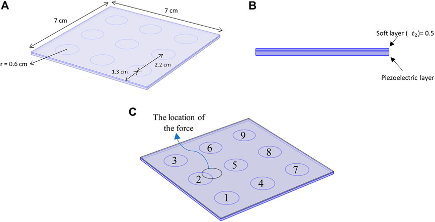
FIGURE 9. A 7 cm
To better simulate the skin, it is necessary to use appropriate boundary conditions. It is assumed that all lower edges of the micro-porous PU-PZT composite material have simply supported constraint. Also, a spring foundation is placed under the sensor to mimic the skin’s properties. Different values for the young’s modulus of human skin have been reported. In ref (Boyer et al., 2009), the young’s modulus of the forearm skin was said to be 13.2 kPa–33.4 kPa in a dynamic indentation test with indentation depth of 1 μm–10 μm/100 μm–500 μm. In this application, a spring foundation with young’s modules of 20 kPa and a depth of 2 cm is selected.
This sensor configuration can be integrated with other structures due to its flexibility and provides an excellent resolution. In this structure, there is no need for many small electrodes for a good resolution. Due to the flexibility of the system, electrodes can sense the force in any location. Further increases in sensor’s resolution can be achieved by using neural networks for detecting the touch location, which can be investigated in our future works.
Some parameters affect the functionality and output of the proposed sensor. Some of them are the thickness of the piezoelectric layer, the thickness of the soft layer, and circuit resistance. For the analysis, the force applied to the surface is circular with a diameter of 1 cm to induce a finger-like sensation. The simulations were done in the frequency domain, and the applied force is harmonic. Of course, the static touch can be detected too, but there are some problems when we have long-term contacts due to the discharge of the piezoelectric material. We assign a number to each electrode for the following analysis and apply force to a fixed location as in Figure 9.
The first parameter that is taken into account is piezoelectric layer thickness. As Figure 10, for electrodes near the applied force (electrodes 5 and 2), the output voltage will increase by increasing the piezoelectric thickness, but other voltages don’t experience a notable change. In the previous part, it was observed that in the simpler mathematical model, by increasing the piezoelectric thickness, the 31 mode output voltage decreases. Also, according to Eq. 3, the 33 mode output voltage increases with increasing the piezoelectric thickness. Here, the electrode 2 is directly under the pressure. Consequently, increasing the thickness significantly increases the output voltage of the sensor (Figure 10) while electrode 5 does not experience much increase. We should mention that although increasing piezoelectric layer increases the effective output voltage, but a delicate and thin sensor is preferred for tactile applications.
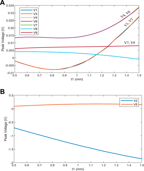
FIGURE 10. The effect of piezoelectric layer thickness (t1) on the output voltage. (Applied force has the same position as Figure 9 and with the magnitude of 2 N and soft layer thickness is 0.5 mm). (A) low voltage outputs, (B) high voltage outputs.
The same analysis has been performed for the soft layer on the top of the piezoelectric layer as Figure 11A. The figure shows that by increasing the thickness of the soft layer, the output voltages increase significantly, but no notable trend was observed for electrodes far from the applied force.
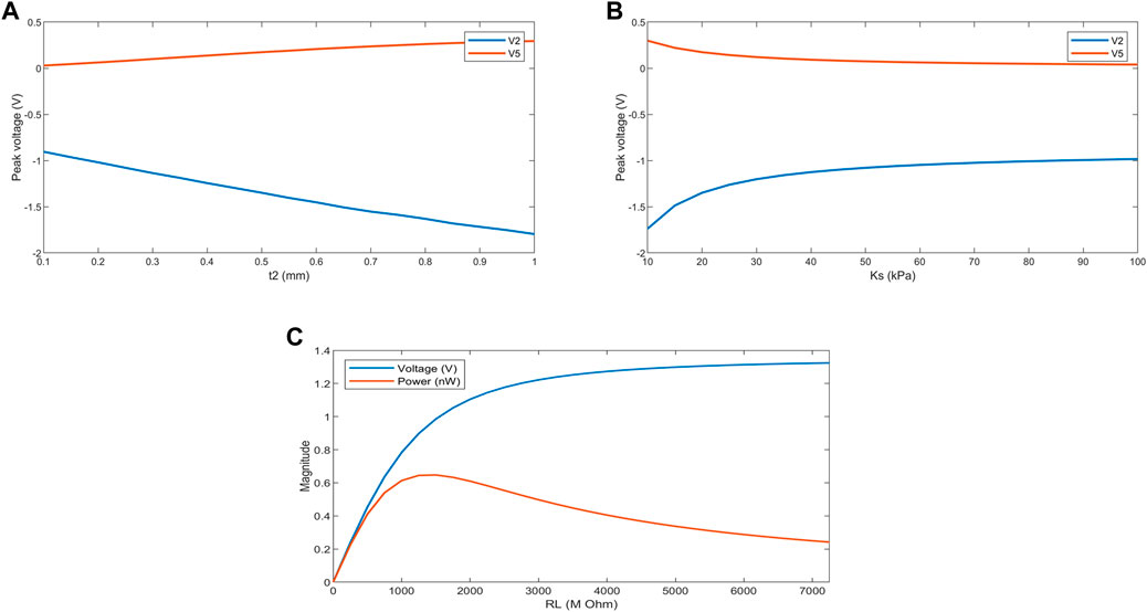
FIGURE 11. The effect of (A) soft layer thickness, (B) spring foundation young’s modulus, and (C) circuit resistance on the high output voltages. (Applied force has the same position as Figure 9 and with the magnitude of 2 N and for (A), the piezoelectric layer thickness is 1 mm, while for (B) and (C) piezoelectric layer thickness and soft layer thickness are 1 mm and 0.5 mm, respectively).
Another parameter that can affect the outputs is the surface properties on which the sensor is mounted. This is considered in the model as the young’s modulus for the spring foundation. The young’s modulus for forearm skin was reported roughly between 10 kPa and 100 kPa (Boyer et al., 2007; Boyer et al., 2009; Khaothong, 2010). Figure 11B shows the effect of this parameter on sensor output. It is observed that for a more rigid surface, the output voltages will be reduced because of the lower bending deformation that occurs in the piezoelectric layer.
Another critical parameter is circuit resistance for piezoelectric sensors. This can affect the output voltage and power generated by an electrode. Figure 11C shows this dependence, and as we see, even though the voltage constantly increases with increasing the resistance, the power forms a peak at about 1,000 MΩ and then decreases.
4 Conclusion
This work has analyzed and evaluated the application of recently developed micro-porous PU-PZT composite material as a soft sensor. We studied the dynamic response of a PU-PZT sensors in 33 and 31 modes and compared it with other commonly utilized piezoelectric materials. The comprehensive properties of the micro-porous PU-PZT composite material required for dynamic analysis of the sensor response were estimated using the effective field method and partially available experimental data, and the optimum value for particles aspect ratio was identified as 0.1326. These properties were used further in our mathematical and finite element model. The functionality of the micro-porous PU-PZT composite material was investigated and it was observed that the output voltage of the micro-porous PU-PZT composite exhibits 295% improvement compared to the output voltage obtained from the bulk PZT-5A in a similar loading condition in 31 mode. In addition, compared to the other materials, micro-porous PU-PZT composite has a lower fundamental resonant frequency, which is an important factor for designing resonators and mechanical energy harvesters. Notably, the flexibility of the sensor is crucial for integrating the sensor within a system, and the micro-porous PU-PZT composite has the highest flexibility among common materials used in sensor design. The effect of the piezoelectric layer, sensor diameter, and middle layer thickness on the performance of the PU-PZT based sensor was also investigated. Motivated by the application of particulate PU-PZT composites in large area sensors, a sensor consisting of discrete electrodes on a micro-porous PU-PZT composite layer was developed and analyzed in COMSOL®. Results of this study show that the micro-porous PU-PZT composite is a great candidate for applications in soft sensors, especially large area soft sensors, due to its flexibility and high sensitivity. This analysis provides a baseline for designing novel soft sensors using the micro-porous PU-PZT composite material for flexible, large area sensing implementations.
Data availability statement
The original contributions presented in the study are included in the article/supplementary material, further inquiries can be directed to the corresponding author.
Author contributions
AG performed the simulations, analyzed the data, and wrote the manuscript. HM and HK supervised the research and interpreted the results. All authors reviewed and approved the manuscript.
Conflict of interest
The authors declare that the research was conducted in the absence of any commercial or financial relationships that could be construed as a potential conflict of interest.
Publisher’s note
All claims expressed in this article are solely those of the authors and do not necessarily represent those of their affiliated organizations, or those of the publisher, the editors and the reviewers. Any product that may be evaluated in this article, or claim that may be made by its manufacturer, is not guaranteed or endorsed by the publisher.
References
Acer, M., Salerno, M., Agbeviade, K., and Paik, J. (2015). Development and characterization of silicone embedded distributed piezoelectric sensors for contact detection. Smart Mat. Struct 24 (7), 075030. doi:10.1088/0964-1726/24/7/075030
Ali, G., and Hamideh, K. (2021). “Mathematical modeling and dynamic analysis of Bi-layer micro-porous piezoelectric sensors,” in Eleventh International Conference on Acoustics and Vibration, Tehran, December 8, 2021. Available at: https://civilica.com/doc/1395208.
Almusallam, A., Luo, Z., Komolafe, A., Yang, K., Robinson, A., Torah, R., et al. (2017). Flexible piezoelectric nano-composite films for kinetic energy harvesting from textiles. Nano Energy 33, 146–156. doi:10.1016/j.nanoen.2017.01.037
Babu, I., and de With, G. (2014). Highly flexible piezoelectric 0–3 PZT–PDMS composites with high filler content. Compos. Sci. Technol 91, 91–97. doi:10.1016/j.compscitech.2013.11.027
Bhardwaj, N., Gupta, A., Choong, K., Wang, C., and Ohmori, H. (2012). Transverse vibrations of clamped and simply-supported circular plates with two dimensional thickness variation. Shock Vib 19 (3), 273–285. doi:10.1155/2012/132969
Biglar, M., and Mirdamadi, H. R. (2016). Configuration optimization of piezoelectric patches attached to functionally graded shear-deformable cylindrical shells considering spillover effects. J. Intelligent Material Syst. Struct, 27 (3), 295–313. doi:10.1177/1045389x14566528
Biglar, M., Mirdamadi, H. R., and Danesh, M. (2014). Optimal locations and orientations of piezoelectric transducers on cylindrical shell based on gramians of contributed and undesired Rayleigh–Ritz modes using genetic algorithm. J. Sound Vib 333 (5), 1224–1244. doi:10.1016/j.jsv.2013.10.025
Biglar, M., and Mirdamadi, H. R. (2014). Integrated and consistent active control formulation and piezotransducer position optimization of plate structures considering spillover effects. Shock Vib 2014, 14. doi:10.1155/2014/276714
Boyer, G., Laquièze, L., Le Bot, A., Laquièze, S., and Zahouani, H. (2009). Dynamic indentation on human skin in vivo: Ageing effects. Skin Res. Technol 15 (1), 55–67. doi:10.1111/j.1600-0846.2008.00324.x
Boyer, G., Zahouani, H., Le Bot, A., and Laquieze, L. (Editors). “In vivo characterization of viscoelastic properties of human skin using dynamic micro-indentation”, Annu Int Conf IEEE Eng Med Biol Soc. 2007, 2007, 4584-7. doi:10.1109/IEMBS.2007.4353360
Chuang, C-H., Dong, W-B., and Lo, W-B. (Editors). Flexible piezoelectric tactile sensor with structural electrodes array for shape recognition system (IEEE). Proceedings of the International Conference on Sensing Technology, 30 November, 2008, Taipei, Taiwan.
Shih, B., Drotman, D., Christianson, C., Huo, Z., White, R., Christensen, H. I., et al. (Editors). (2017) Custom soft robotic gripper sensor skins for haptic object visualization. Proceedings of the IEEE/RSJ international conference on intelligent robots and systems (IROS), (IEEE). 24-28 September, 2017, Vancouver, BC, Canada.
Glushanin, S., Topolov, V. Y., and Krivoruchko, A. (2006). Features of piezoelectric properties of 0–3 PbTiO3-type ceramic/polymer composites. Mater. Chem. Phys 97 (2-3), 357–364. doi:10.1016/j.matchemphys.2005.08.027
Huang, J. H., and Kuo, W-S. (1996). Micromechanics determination of the effective properties of piezoelectric composites containing spatially oriented short fibers. Acta Mater 44 (12), 4889–4898. doi:10.1016/s1359-6454(96)00090-0
Huang, J. H., and Yu, J. (1994). Electroelastic Eshelby tensors for an ellipsoidal piezoelectric inclusion. Compos. Eng 4 (11), 1169–1182. doi:10.1016/0961-9526(95)91290-w
Ippili, S., Jella, V., Kim, J., Hong, S., and Yoon, S-G. (2018). Enhanced piezoelectric output performance via control of dielectrics in Fe2+-incorporated MAPbI3 perovskite thin films: Flexible piezoelectric generators. Nano Energy 49, 247–256. doi:10.1016/j.nanoen.2018.04.031
Khanbareh, H., de Boom, K., Schelen, B., Scharff, R., Wang, C., van der Zwaag, S., et al. (2017). Large area and flexible micro-porous piezoelectric materials for soft robotic skin. Sensors Actuators A Phys 263, 554–562. doi:10.1016/j.sna.2017.07.001
Khanbareh, H., Topolov, V. Y., and Bowen, C. R. (2019). Piezo-particulate composites: Manufacturing, properties, applications. Berlin, Germany: Springer.
Khaothong, K., In Vivo measurements of the mechanical properties of human skin and muscle by inverse finite element method combined with the indentation test. IFMBE proceedings 31, 1467–1470. doi:10.1007/978-3-642-14515-5_374
Kim, H., and Kim, Y. (2018). High performance flexible piezoelectric pressure sensor based on CNTs-doped 0–3 ceramic-epoxy nanocomposites. Mater. Des 151, 133–140. doi:10.1016/j.matdes.2018.04.048
Kim, S. H., Kwon, Y., Kim, K., and Cha, Y. (2020). Estimation of hand motion from piezoelectric soft sensor using deep recurrent network. Appl. Sci 10 (6), 2194. doi:10.3390/app10062194
Lee, H. J., Zhang, S., Bar-Cohen, Y., and Sherrit, S. (2014). High temperature, high power piezoelectric composite transducers. Sensors 14 (8), 14526–14552. doi:10.3390/s140814526
Leo, D. J. (2007). Engineering analysis of smart material systems. Hoboken, New Jersey: John Wiley & Sons.
MIT Technology review J, 2006. MIT Technology review J, Available from: https://www.technologyreview.com/2006/06/09/274003/tactile-sensor-as-sensitive-as-human-skin/ (Accessed May 18, 2022).
Reddy, J. N. (2017). Energy principles and variational methods in applied mechanics. Hoboken, New Jersey: John Wiley & Sons, 560.
Thuruthel, T. G., Shih, B., Laschi, C., and Tolley, M. T. (2019). Soft robot perception using embedded soft sensors and recurrent neural networks. Sci. Robot 4 (26), eaav1488. doi:10.1126/scirobotics.aav1488
Wang, Y., Zheng, J., Ren, G., Zhang, P., and Xu, C. (2011). A flexible piezoelectric force sensor based on PVDF fabrics. Smart Mat. Struct 20 (4), 045009. doi:10.1088/0964-1726/20/4/045009
Xu, R., and Kim, S. (2012). Figures of merits of piezoelectric materials in energy harvesters. Proceedings of the PowerMEMS 2012, Atlanta, GA, USA, December 2–5, 2012, 464–467.
Yaghootkar, B., Azimi, S., and Bahreyni, B. (2017). A high-performance piezoelectric vibration sensor. IEEE Sens. J 17 (13), 4005–4012. doi:10.1109/jsen.2017.2707063
Keywords: large-area sensor, soft robotics, piezoelectric, smart skin, flexible sensors
Citation: Ghadami A, Mirdamadi HR and Khanbareh H (2022) Dynamic modeling and analysis of flexible micro-porous piezoelectric sensors applicable in soft robotics. Front. Electron. Mater. 2:1023415. doi: 10.3389/femat.2022.1023415
Received: 19 August 2022; Accepted: 12 October 2022;
Published: 07 November 2022.
Edited by:
Yan Zhang, Central South University, ChinaCopyright © 2022 Ghadami, Mirdamadi and Khanbareh. This is an open-access article distributed under the terms of the Creative Commons Attribution License (CC BY). The use, distribution or reproduction in other forums is permitted, provided the original author(s) and the copyright owner(s) are credited and that the original publication in this journal is cited, in accordance with accepted academic practice. No use, distribution or reproduction is permitted which does not comply with these terms.
*Correspondence: Ali Ghadami, YWxpLmdoYWRhbWlAbWVjaC5zaGFyaWYuZWR1