 Tingchun Li
 Liu Yang
 Qingwen Zhu
 Daowei Liu1,2
95% of researchers rate our articles as excellent or good
Learn more about the work of our research integrity team to safeguard the quality of each article we publish.
Find out more
ORIGINAL RESEARCH article
Front. Ecol. Evol. , 31 October 2023
Sec. Environmental Informatics and Remote Sensing
Volume 11 - 2023 | https://doi.org/10.3389/fevo.2023.1291359
This article is part of the Research Topic Response and Catastrophe Mechanisms of Geotechnical Underground Exploration: Theories and Numerical Modeling View all 14 articles
Introduction: The technology of gob-side entry retaining without coal pillars in close (distance) coal seams is still immature, and the roof control and support technology in this case is not perfect.
Methods: In this paper, the coupled support technology of a composite rock beam roof under close coal seams is systematically studied by using theoretical analysis, numerical simulation and field test.
Results: Both the floor slip calculation results and numerical simulations indicate that the vertical failure depth in the plastic zone of the #8 coal seam has not penetrated the roof of the #9 coal seam after mining, which is consistent with the field electronic imaging results. A theoretical formula for a composite rock beam model anchored by high-prestressed anchor cables was derived, and a formula for the optimal spacing of anchor cables under noncompressive shear failure of the roof was obtained. Identification of the internal stress hazard region of the rock beam provides a basis for determining the locations of vertical support. Through numerical simulation of different support schemes, including roof cutting, arrangement of high-prestressed anchor cables, and setting up of vertical supports, roof cutting was found to effectively reduce the stress of supporting structure and roof pressure. Setting up of vertical supports can reduce the roof convergence by 25.2%, and coupling with anchor cables can reduce the convergence by more than 49.1%. The feasibility of this support scheme was verified through field tests, with a maximum convergence of 99 mm between the roof and floor.
Discussion: This two-way verification approach, in which the damage degree of the roof of a close coal seam is analyzed through multiple means, targeted support plans are proposed, the support mechanisms are explored, and feedback is conducted through field tests, plays a certain guiding role in solving roof control of the gob-side entry retaining under similar geological conditions.
Coal seams with a small interlayer spacing in which the collapse zone caused by mining of the lower coal seam and the damage zone of the floor of the upper coal seam are connected are called close (distance) coal seams (Cheng et al., 2020). This type of coal seam is widely found in many major coal mining countries, such as China, Russia, and the United States (Peng et al., 2019). The difficulty of close coal seam mining lies in the more severe roof control conditions of the roadway (Tian et al., 2020). The mining of coal seams can lead to significant changes in the stress (Suchowerska et al., 2013; Liu et al., 2016) and bearing capacity of the surrounding rock (Qin et al., 2021; Shang et al., 2023) of subsequent coal seams. Especially in terms of the integrity of the surrounding rock, the destruction of the floor of the mined-out area of the coal seam first directly mined leads to a decrease in the integrity of the roof of the coal later mined (Zhang et al., 2013; Ning et al., 2020). Due to the difficulty of mining and extreme uncertainty in support design, the mining of close coal seams is often abandoned. With the continuous development of the “green mining of coal” concept, abandoning the recovery of close coal seams has become inconsistent with the requirements of the times.
Therefore, many scholars have conducted research on the failure mechanism and support control of the surrounding rock of close coal seams. Zhao et al, 2020; Zhao et al, 2021 found that the principal stress of a close coal roadway undergoes a certain angular deflection, and the plastic zone of the surrounding rock develops diagonally. Shang et al. (2019) concluded that a close coal seam roadway should not be located under a coal pillar; otherwise, it will be affected by stress concentration. Liu et al. (2022a) analyzed the rock failure process between two coal seams based on the “block dispersion” structural model. Li et al. (2022a) proposed four stress stages of the roof under repeated mining conditions in close coal seams based on similarity model experiments. Wang et al. (2023) used a fractal dimension to divide the development of close-distance coal seam roof fractures into zones. The research of Cheng et al. (2021a) showed that the gangue area after mining the upper coal seam has a stress weakening effect on the lower coal seam.
The research results of the damage mechanism effectively guide the design of the support scheme. To control the instability and deformation of the surrounding rock of a close coal seam, scholars have proposed many strategies for surrounding rock control. For example, the integrity of the surrounding rock can be improved by grouting the roof to harden it, and the surrounding rock can be controlled by using water jet cutting to release pressure on the roof (He et al., 2021; Li et al., 2022c). Some scholars have also conducted zonal support design for roadways from the perspective of surrounding rock stress control (Chen et al., 2022) to explore reasonable support parameters (Yan et al., 2015). In addition, some scholars have studied roof leakage (Kong et al., 2021; Li et al., 2022b), deduced the roof instability mechanism, and proposed targeted solutions. Additionally, to deal with support environments similar to close coal seams, efforts are being made to improve the performance of support tools (Wang et al., 2022).
In summary, research on close (distance) coal seam support technology has made significant progress (Table 1), and the relevant plans have greatly inspired us. To improve the recovery rate and avoid waste of coal resources, coal pillar-free mining technology is widely used. The application of this technology to close coal seams is also the only way to achieve “green mining”. However, there are few cases of gob-side entry retaining in close coal seams, and roadway support design under these conditions is a completely new challenge. Since the promotion of the new Austrian tunneling method (NATM), the concept of the surrounding rock as a load-bearing structure has been recognized by engineers (Tan et al., 2019; Zhang et al., 2019; Wang and Wang, 2019). If the self-bearing capacity of the surrounding rock can be fully utilized and supplemented by roof cutting to reduce pressure (Tao et al., 2018; Hu et al., 2023; Li et al., 2023), then the support cost can be significantly reduced, and the safety can be improved.
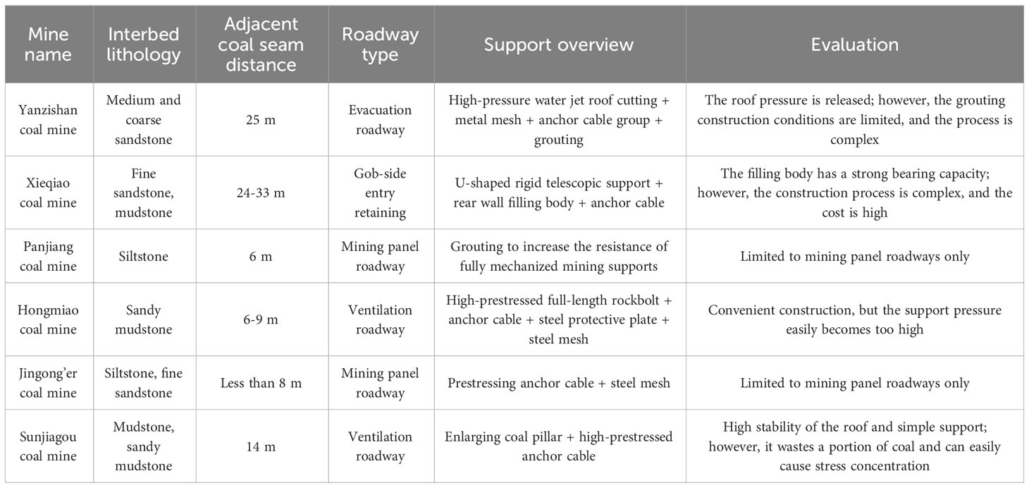
Table 1 Overview of the support schemes for a close coal seam roadway.
In this paper, taking the Xinchazhuang coal mine as the background, we judge the damage degree of the roof of the lower coal seam (#9 coal seam) through a comprehensive study of the upper coal seam (#8 coal seam) mining and propose a targeted roof control and support scheme for the roof of the lower coal seam retained roadway. Then, we verify the feasibility and effect of the support via numerical simulation. Finally, we conduct field tests and field monitoring to complete final verification of the scheme. This research method and the corresponding results are expected to provide a reference for the same type of gob-side entry retaining.
The Xinchazhuang coal mine is in Shiheng town, Feicheng city, Shandong Province, China (Figure 1A), and the main coal seams being mined at this stage are the #8 and #9 coal seams. The belt roadway of the 91010 panel is to be retained, which represents the first retained roadway of the initial mining panel for the #9 seam coal. Given its proximity to the upper coal seam, the support design becomes more intricate compared to that for single coal seams. The average distance from the return #8 coal seam to the 91010 panel is 7.3 m. Figure 1B shows the relative positions of the two mined coal seams. The burial depth of the 91010 panel is 498-551 m. The mining length for the panel is 394 m. The length of the panel is 105 m (Figure 1C). The mechanical parameters are shown in the Table 2.
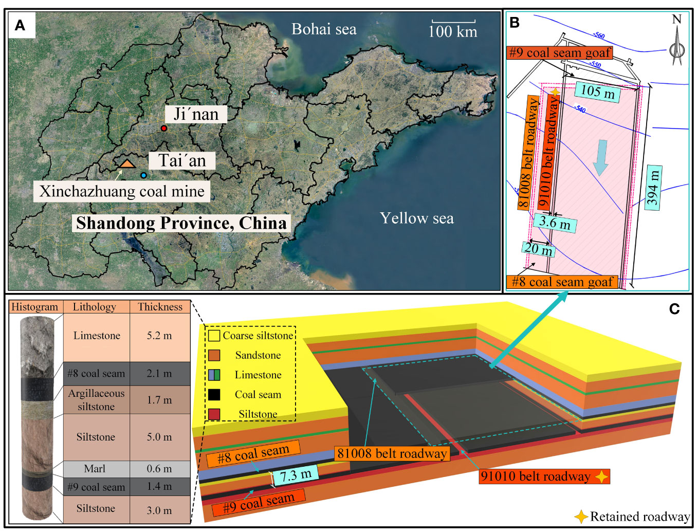
Figure 1 Overview of engineering conditions. (A) Location of the Xinchazhuang coal mine. (B) Relative position of coal seams. (C) Lithology and three-dimensional layout of the panel.
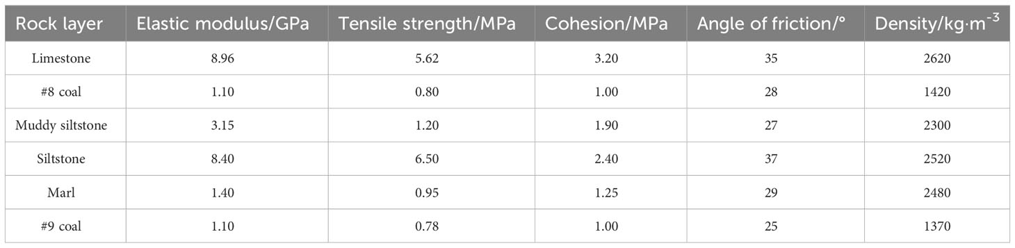
Table 2 Mechanical parameters of the surrounding rock.
After #8 coal recovery, the collapsed roof material acts on the floor of the mining area and affects the rock body within a certain depth. When the pressure of the collapsed rock to which the rock body of the floor is subjected is greater than the critical pressure, the rock body within this range will form a plastic deformation zone. When plastic deformation continues to develop into plastic damage, the floor deformation peaks, and a continuous slip surface is formed within the floor (Cheng et al., 2021b). According to the theoretical analysis of the floor slip field (Zhang et al., 2012; Sun et al., 2021; Zhang et al., 2021; Qi et al., 2022), the maximum depth of impact on the floor after mining of the upper coal seam can be calculated by the following equation:
where Ms is the mining height of the #8 coal seam, m; ks is the stress concentration factor; γ is the average unit weight of the overlying rock layer on the stope, kN/m3; Hs is the burial depth of the #8 coal seam, m; C is the cohesion of coal; φ is the friction angle of coal; φf is the friction angle of the floor rock; ξ is the triaxial stress coefficient; and f is the friction coefficient of the coal seam and floor contact surface.
Substituting the actual parameters of the studied site into eq 1, the maximum damage depth of the floor of the #8 coal mining area is calculated to be 5.44 m. The average distance between the two coal seams is 7.3 m, and the damage depth completely passes through the #9 coal roof. The theoretical calculation shows that there is still a layer of fairly intact roof in the #9 coal roof.
To further verify the failure characteristic of the #9 coal roof, a simulation study was conducted on close coal seam mining. The simulated test uses the same downward mining sequence as on field. The #8 coal model mining height is designed to be 2.1 m. According to the filling gangue crushing and expansion coefficient, the #8 coal collapse filling zone height is 7.35 m. After the #8 coal seam mining is completed, the range of the collapse zone in the extraction area is filled with gangue to simulate the rock collapse in the collapse zone after recompaction. The #8 coal collapse filling zone parameters were obtained through several simulation inversions, and the filling compaction gangue mechanical parameters are shown in Table 3.

Table 3 Mechanical parameters of the filled and compacted gangue.
Based on the double-yield model (Yan et al., 2019), the collapsed and backfilled rock showed strain-hardening characteristics and was able to bear pressure again. The simulated plasticity diagram of the upper coal seam after collapse and recompaction is shown in Figure 2, and the results confirm the existence of intact rock in the #9 coal roof.
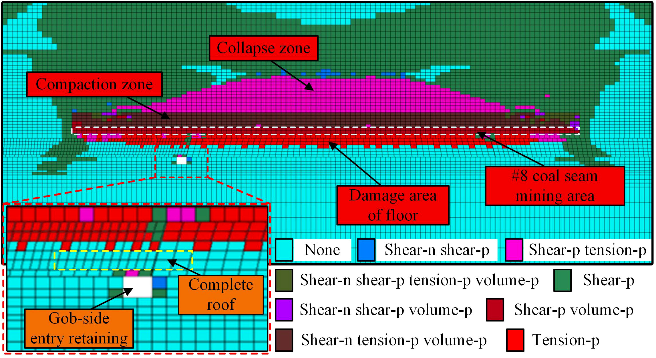
Figure 2 Plasticity distribution of the upper coal seam after compaction.
Based on the theoretical calculation and numerical simulation results, lithology verification of the roof is carried out in the field via drill hole observation. The fracture distribution of the roof is shown in Figure 3.
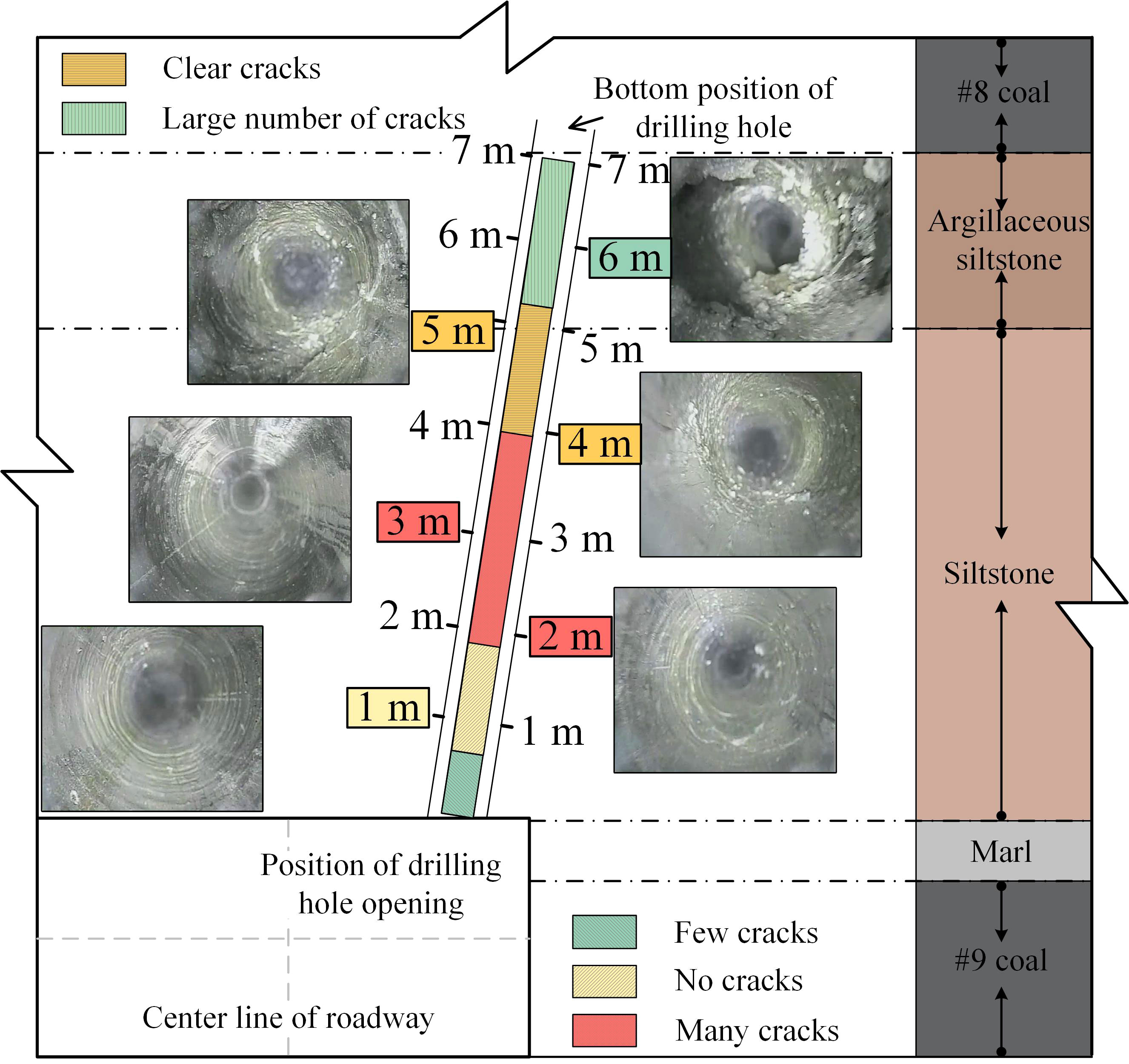
Figure 3 Cracks of the roof.
Within the drill hole depth of 1-2 m, a fairly intact rock formation is observed. There are very few cracks in the formation, and the drill hole wall is smooth. The rock layers at the 2-5m position are subject to varying degrees of damage There are small cracks in this section, and as the hole depth increases, the crack depth also increases. Approximately 6-7 m of the rock layer is relatively broken. There is clear debris slag in the drill hole, the rock is broken on a large scale, and the cracks are well developed. This suggests that the site is heavily influenced by upper coal reclamation.
After comprehensive research including a site survey, it is found that there is 1-2 m of intact rock in the roof of the retained roadway, which indicates that later roof control and support and gob-side entry retaining may be possible.
The presence of intact rock in the #9 coal roof provided a basis for the practice of anchoring the rock with high-prestressed anchor cables and thus achieving rock beam modification. Before the start of mining, high-prestressed anchor cable support was applied to the roof of coal roadway #9, and the rock affected by the mining of the upper coal seam was reextruded and merged with the more intact rock to establish a new composite rock beam model (Figure 4).
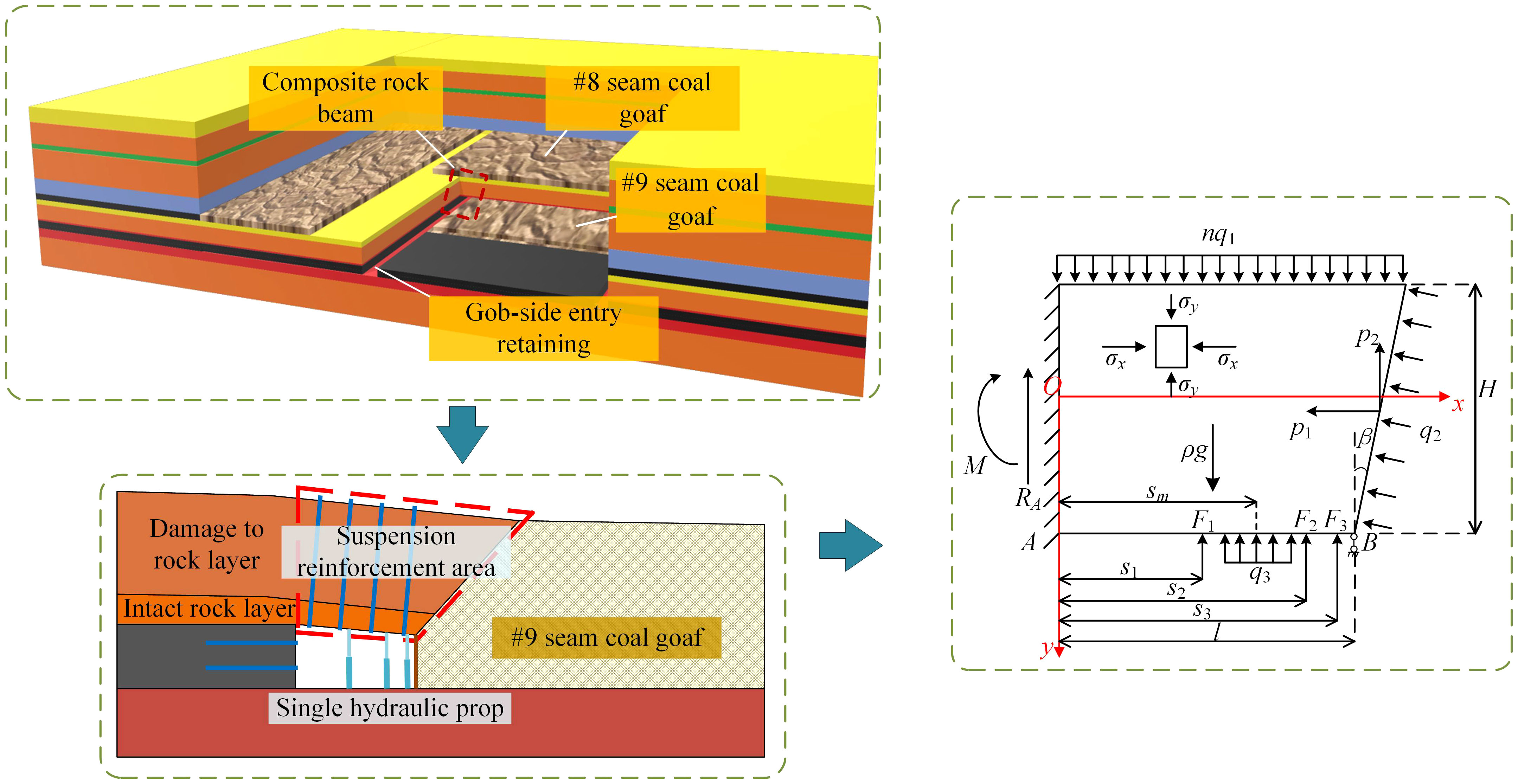
Figure 4 Mechanical model of the composite rock beam on the roof.
To facilitate the calculations, reasonable assumptions were made about the model:
(1) The anchor cable anchoring force is large enough to closely anchor the rock strata affected by #8 coal mining as a whole with the more intact rock strata, which is treated as a plane strain problem, and the axial width of the retained roadway is 1.
(2) The model is established in the dynamic pressure stage of the roof, which is the most affected stage. To simplify the calculation, one end of the composite rock beam of the roof is a solid coal gangue solid support boundary. Due to the special working conditions, the roof of the goaf collapses rapidly and can support the cantilever end, so one end is a simply supported boundary of gangue single support. The support load provided by the collapsed gangue at the roof cutting end is a uniformly distributed load.
(3) The overlying load on the roof is a uniform static load with a dynamic pressure coefficient of n.
Then, the #9 coal support-modified rock layer is subjected to the load to determine the roles of the uniform load of the overlying rock layer on the composite rock beam nq1, the load of the collapsed gangue on the roof q2, the roadway anchor cable support uniform load q3, and the single-support concentration forces F1, F2, and F3 in the roadway. In addition, in Figure 4, p1 and p2 are the horizontal and vertical combined force components at the cutting side under an external load, N; RA is the support reaction force acting at the solid support end, N; M is the support reaction moment acting on the solid support end, N·m; s1, s2 and s3 are the horizontal distances from F1, F2 and F3 to the solid support end, respectively, m; sm is the horizontal distance from the equivalent load q3 to the solid support end, m; β is the angle between the cutting side and the vertical direction; ρ is the average weight of the composite rock beam, N/m3; l is the width of the roadway, m; and H is the height of the composite rock beam, m.
The main form of damage occurring in the composite rock beam is compression–shear damage, so the maximum shear stress is used to measure the stability of the roof. For the convenience of calculation, the method of stress superposition is used to calculate the reasonableness of the support.
The stress distribution at each point inside the rock beam after cutting the roof is in the form of:
When the overlying load acts on the roof, the forces on the cutting side are:
Substituting eq 3 into eq 2 yields the internal stress components of the rock beam under the overlying load: σx1, σy1 and τxy1.
The gangue support force diagram is shown in Figure 5. The larger the load of the gangue on the roof q2 and gangue sinking amount S, the larger the gangue support force is; to simplify the calculation, the support coefficient of the gangue after collapse is set to k, so:
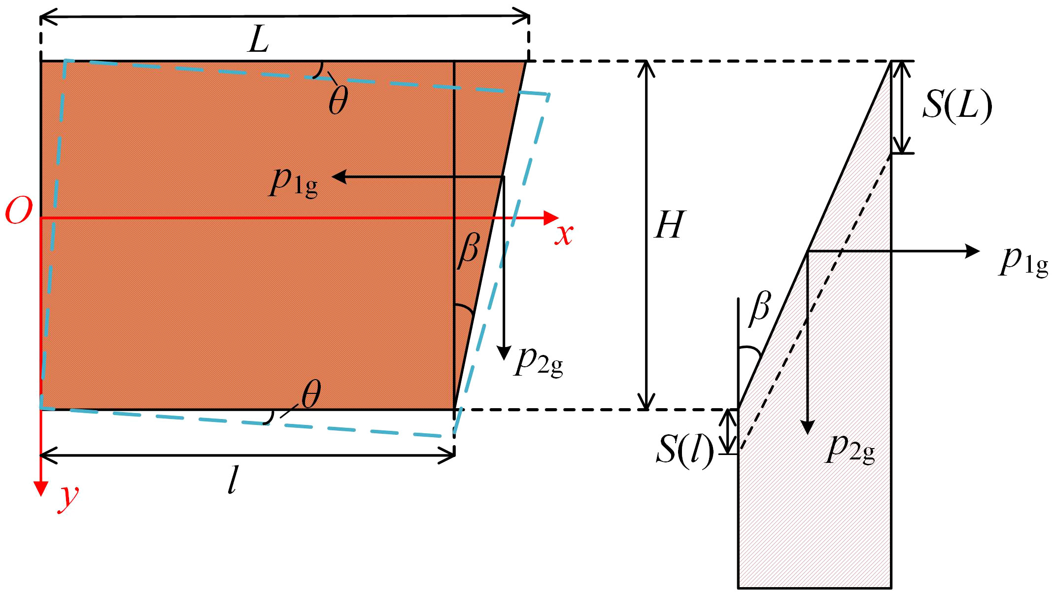
Figure 5 Gangue support force diagram.
Then, the compression of gangue at any point x on the roof is:
S0 is the overall sinkage at the fracture of the roof; θ is the rotation angle of the roof.
The amount of gangue compression on the central axis of the roof rock beam is the average compression:
The vertical combined force of the roof at the intersection of the central axis and the fracture plane is expressed as:
Assuming that the gangue does not transfer vertical shear stress in the compression process and is in ultimate equilibrium, the horizontal combined force can be expressed as follows:
Eqs 7 and 8 can be substituted into eq 2 to obtain the rock beam internal stress components at each point in the gangue support: σx2, σy2 and τxy2.
The single hydraulic prop strut provides concentrated support resistance at the lower surface of the rock beam, and the stress components of the rock beam under the action of the vertical support resistance Fn are:
Since the origin of the coordinate system in this model is different from the above equation, a coordinate transformation is needed, and the equation is:
The support resistance F of the single hydraulic prop is subjected to the support reaction forces RA and RB, and the support reaction forces RA and RB of the solid coal sidewall and goaf side are obtained by solving the mechanical model as follows:
Eqs 9-11 are joined to obtain the stress components of the rock beam under the action of the single hydraulic prop: σx3, σy3 and τxy3.
The rock beam on the roof is subjected to the distributed force of the anchor cable, which can be regarded as a very short length d at the distance from the boundary [-a, a] range to the coordinate origin O. The force dF = q3dδdF in this range is regarded as a very low but concentrated force. Then, the stress components at each point inside the rock beam under the action of the anchor cable distribution force are:
Since the origin of the coordinate system in this model is different from the above equation, a coordinate transformation is needed, and the equation is:
The mechanical model solution is used to obtain the solid coal sidewall and side of the gob support reaction force RAm and RBm as follows:
Then, eqs 12-14 are solved together to obtain the stress components of the rock beam under the action of the anchor cable: σx4, σy4 and τxy4.
According to the anchor cable strength formula and the internal stress of the rock beam (σxn, σyn and τxyn), to ensure that no compressive damage occurs in the rock beam, the optimal reasonable interrow spacings A1 and A2 of the anchor cable should be:
where Fm is the anchor cable anchorage force and Jn is the intermediate variable.
Through the theoretical calculation of floor sliding, numerical simulation and field observation verification, it was determined that there is an intact roof in the #9 coal roof. Using the intact roof of coal #9 as the base, high-prestressed anchor cables were arranged to modify the roof into a composite rock beam. Eq 15 was used to verify the optimal interrow spacing of anchor cables, and rockbolt were used for reinforcement support. The main unknowns are extracted from the composite rock girder internal stress equation to make a three-dimensional map of the distribution of the internal stress components of the rock girder (Figure 6). The most hazard region of the rock beam is located at the bottom of the cutting end. It is proposed to use the form of “one beam and two columns” with higher bearing capacity and better stability to arrange the single hydraulic prop for vertical support. The coupled support scheme of roof cutting + high-prestressed anchor cables + vertical support is finally formed.
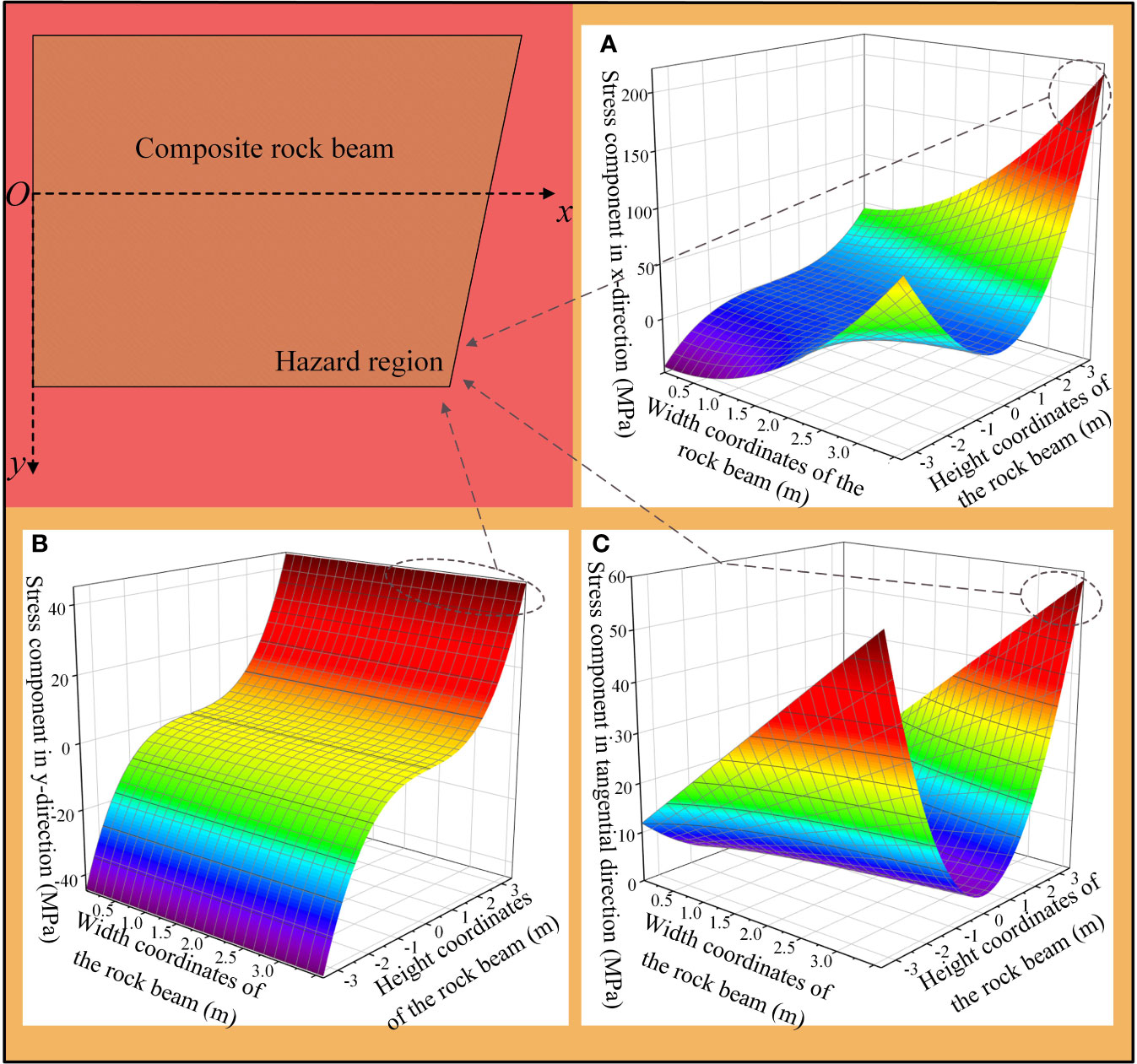
Figure 6 Three-dimensional distribution of stress components. (A) X-direction stress. (B) Y-direction stress. (C) Tangential stress.
To verify the effect of the support scheme and the mechanism of the support action, a simulation test of the support scheme was conducted using FLAC3D simulation software. The scheme design is shown in Table 4.
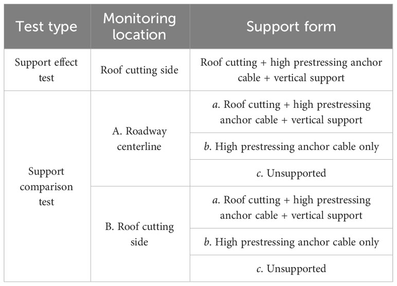
Table 4 Simulation scheme.
The numerical model was built based on FLAC3D software (Jia et al., 2022; Liu et al., 2022b; Sun et al., 2022; Zhu et al., 2023). The model was divided into a total of 574860 units and 620309 nodes. The boundary conditions were set as follows (Figure 7): the displacement of the bottom boundary of the model is restricted in any direction, the horizontal displacement of the four sides is restricted, and the vertical load is applied on the top boundary.
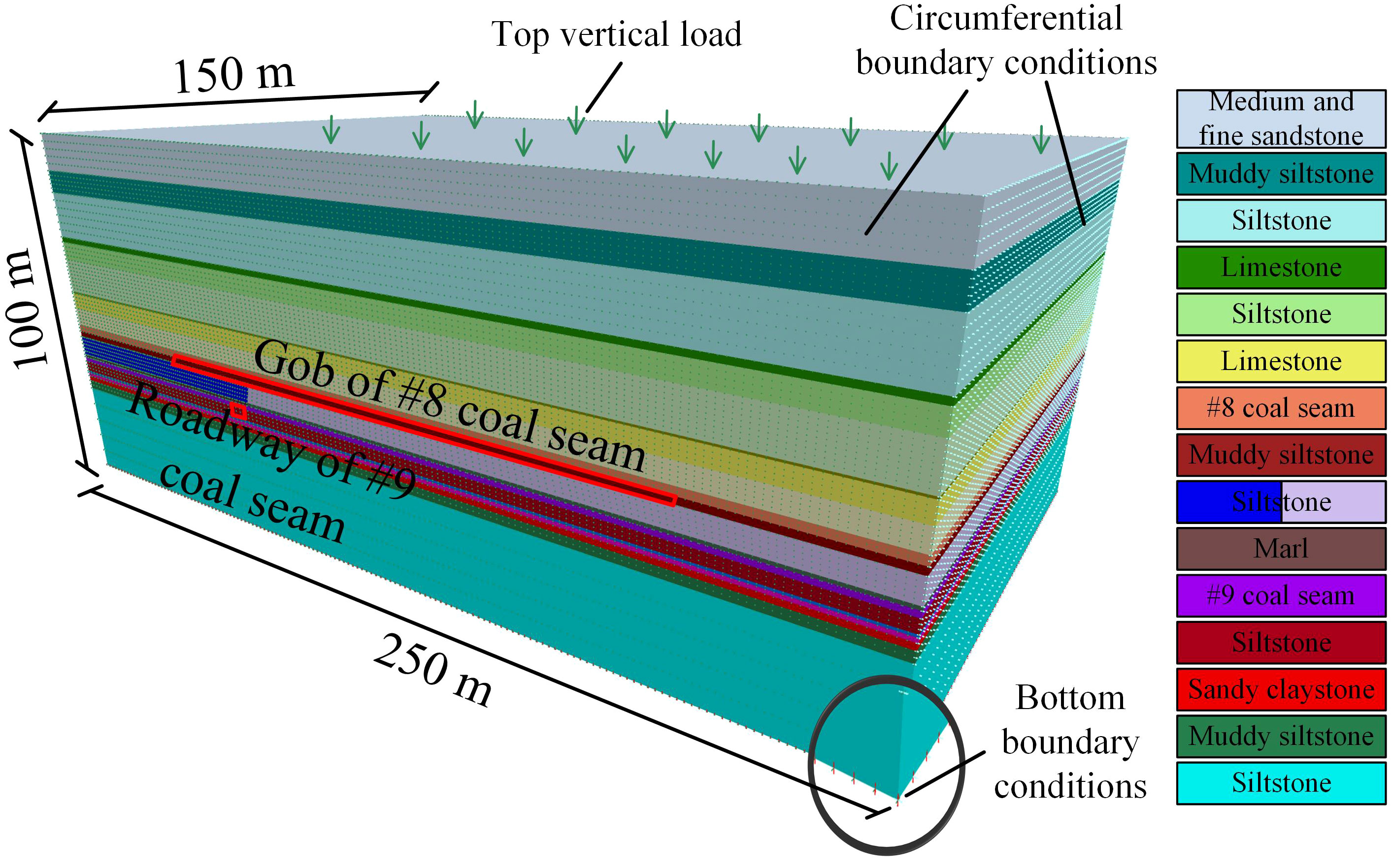
Figure 7 Numerical simulation model diagram.
The mining void area of the #8 coal seam was backfilled using the intrinsic double-yield model to simulate the impact on the roof of the #9 coal seam after collapse of the mining void area (An et al., 2021; Li et al., 2021; Lv et al., 2022; Yu et al., 2022). The numerical model as a whole, except for the mining void of the #8 coal seam, was assigned as the Mohr–Coulomb intrinsic model. Table 5 illustrates the parameters of the support model.
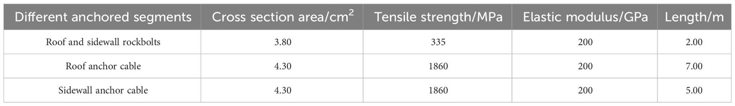
Table 5 Parameters of the support models.
The simulated support was carried out with option a: roof cutting + high-prestressed anchor cables + vertical support. Simulation was performed for mining for a total of 100 m, with a fixed location for monitoring at the 15 m section, collecting the roof and floor displacement data of the roadway at 15 m, 25 m, 35 m, 45 m and 55 m after the return face frame. The simulation results are shown in Figure 8.
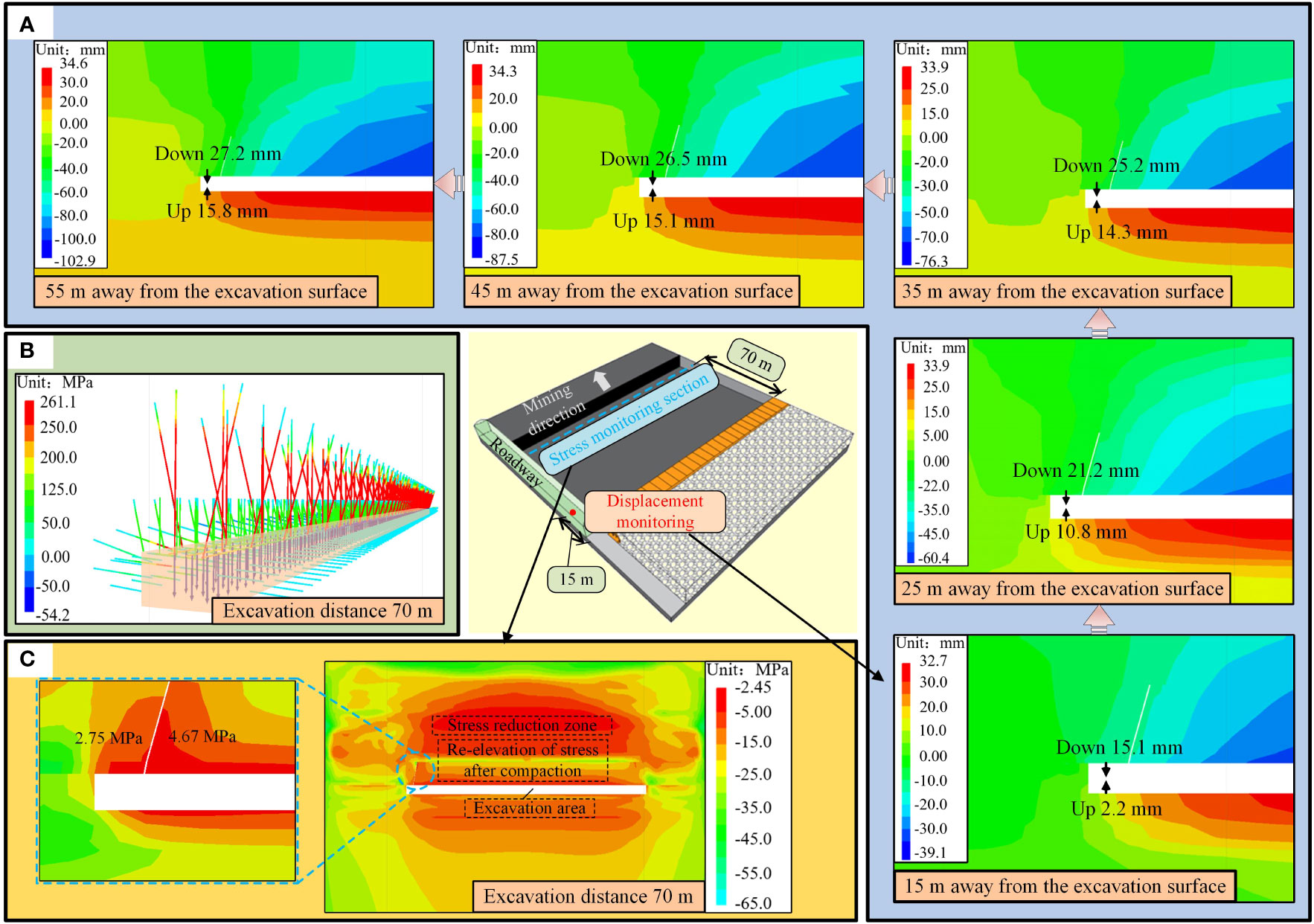
Figure 8 Displacement and stress simulation results. (A) Displacement monitoring results (B) Support stress monitoring results. (C) Stress monitoring results.
The displacement monitoring data in Figure 8A show that the convergence rate of the roof and floor of the roadway gradually decreases and tends to be balanced as the panel is continuously mined. After mining to 70 m, the maximum sinkage of the roof is 27.2 mm, the floor rises 15.8 mm, and the surrounding rock deformation is well controlled. The support stress diagram (Figure 8B) shows that the axial stress of the anchor cables in the gangue is low and that the roof anchor cables and vertical supports play the main supporting role. The maximum stress of the roof anchor cables is 261 MPa, and the stress is concentrated in the middle and lower parts of the anchor cables. From the overall stress monitoring results (Figure 8C), we found that roof cutting effectively blocks the connection between the roadway and the mining area so that the stress on the roof of the roadway is much lower than the stress on the roof of the mining area, and the joint action with the support effectively controls the sinking of the roof.
To confirm the effectiveness and principle of field support, a comparative test was conducted. The test process involved alternating mining and backfilling (Figure 9). The test contents included simulating both the retained roadway option a (Figure 10 L1-L2), the option without retained roadway support b (Figure 10 L3-L4), and the unsupported option c (Figure 10 L5-L6).
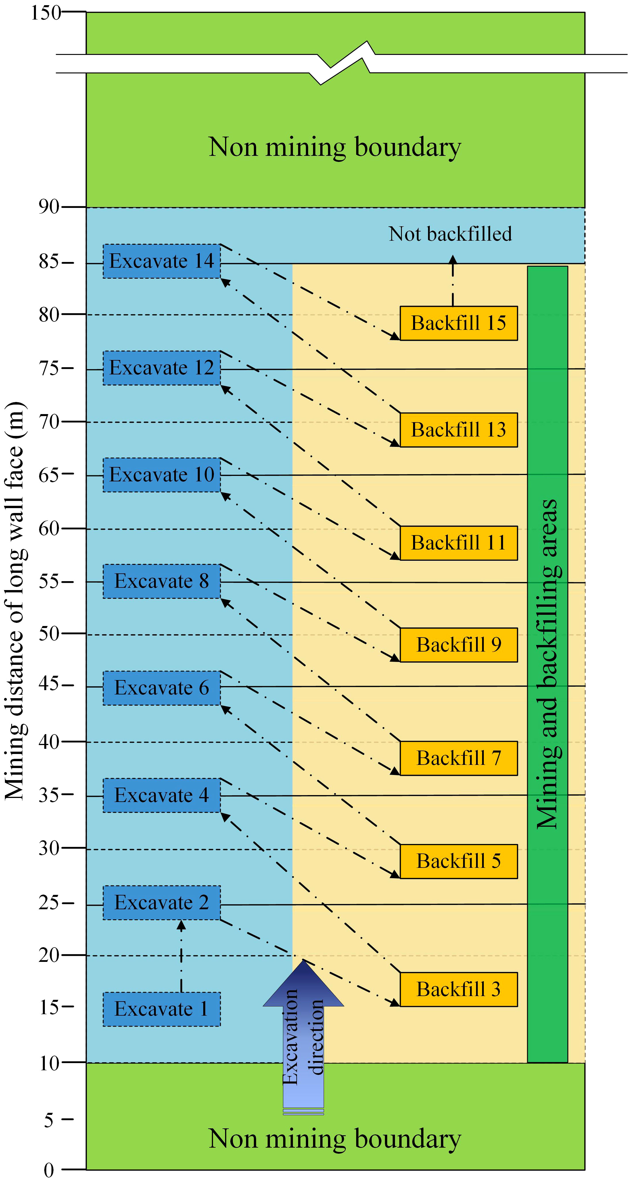
Figure 9 Mining and backfilling steps.
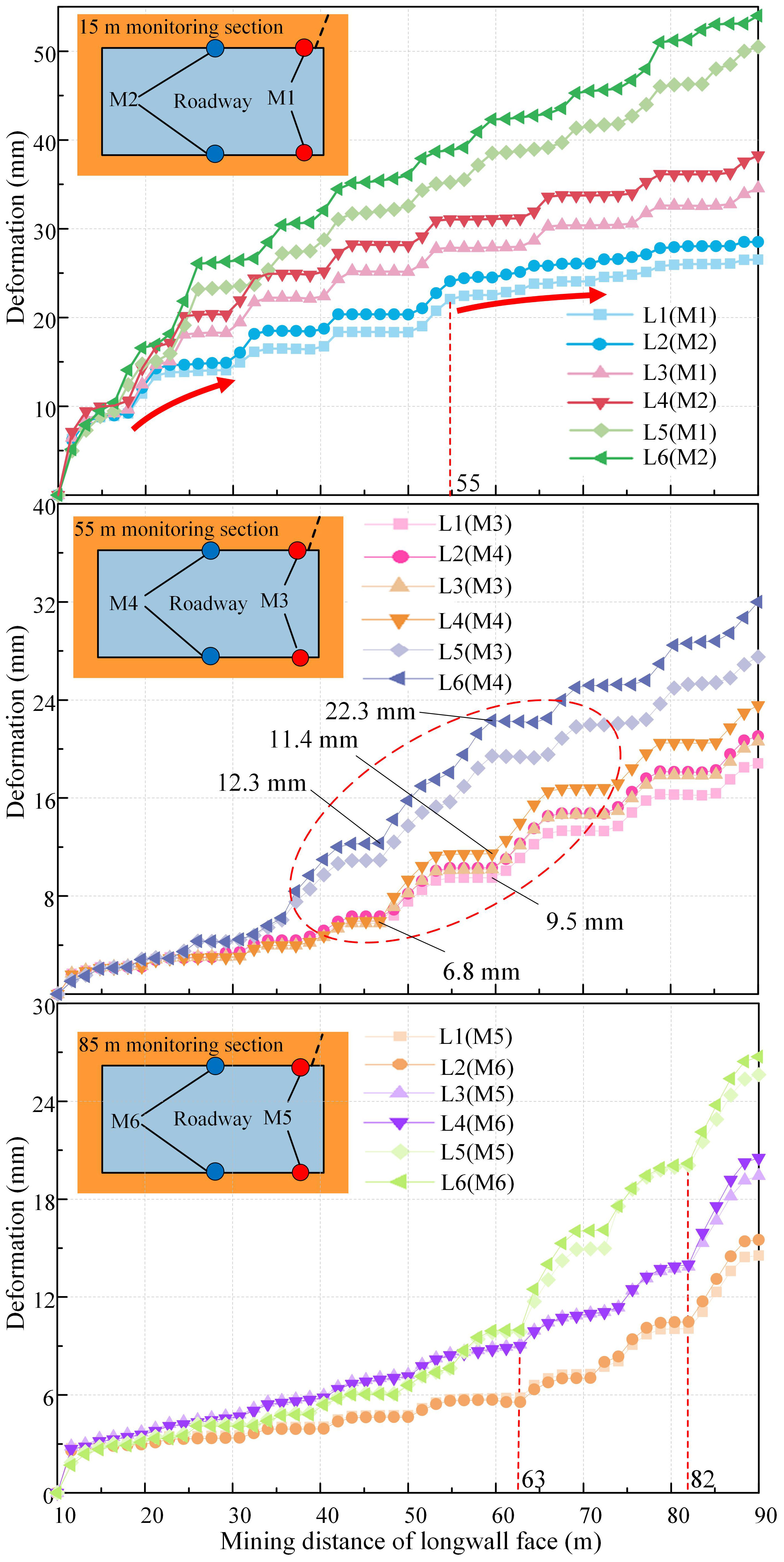
Figure 10 Comparison of simulation test results.
In the comparison simulation test, the design was excavated for a total of 80 m. To avoid boundary effects, the model started mining from a position 10 m from the boundary. The vertical displacements at 15 m, 55 m and 90 m from the boundary were monitored in real time. Data were collected at the cutting line (Figure 10 M1, M3, M5) and centerline (Figure 10 M2, M4, M6) of each monitoring section.
According to the simulated data plotted in Figure 10, the following summary can been made:
(1) In the simulated support, the deformation on the cutting side of the roof was always higher than the deformation at the centerline of the roof, and the cutting side was the key area for support.
(2) The changes in roof displacement during the entire mining and backfilling were recorded at the 15 m monitoring section. The results showed that the support scheme with vertical support started to stabilize when the mining reached 55 m, and the maximum sinkage was only 28.5 mm, which was a reduction in the maximum deformation of the roof by 25.2% compared with the support scheme with only anchor cables and 49.1% compared with the unsupported roadway. With continuous mining of the panel, the deformation of the roof with only anchor cable support and the unsupported roadway significantly increased.
(3) Comparing the results of the 55 m monitoring section, when the panel is pushed past the monitoring position, the changes in the roof and floor for options a-c were as follows: c. no support > b. anchor cable support > a. anchor cable + vertical support. The deformation rate of the roof of the roadway with vertical support was significantly smaller than that of the other two support solutions.
(4) The variation in the roof displacement at the 90 m monitoring section was recorded near the end of mining. The observed data indicated that the presence or absence of vertical support had little influence on the impact range of advanced mining, and in both cases, the deformation rate began to accelerate when the longwall face was 27 m away. The option c deformation speed when the longwall face was 27 m away was faster. Options a and b reached the same speed only at an 8 m distance from the support. This phenomenon also occurred for the 55 m monitoring results.
(5) Combined with the support stress diagram (Figure 8B), under the same vertical support conditions, the maximum stress of the cable of the roadway after roof cutting was 261 MPa, and the maximum stress of the anchor cable of the roadway without roof cutting was 302 MPa; the stress of the cable after roof cutting was reduced by 13.6%.
With the theoretical derivation and numerical simulation results, the design of field roof control and support was carried out for the close coal seam roadway of the Xinchazhuang coal mine. The roof load could be shared by the intact rock layer, and the load borne by the support structure was reduced. To improve the flexibility of the scheme, the adopted scheme used the combined support method of roof cutting + high-prestressed anchor cable + single hydraulic prop in coordination with an articulated roof beam. The design structure of the gob-side entry retaining support is shown in Figure 11.
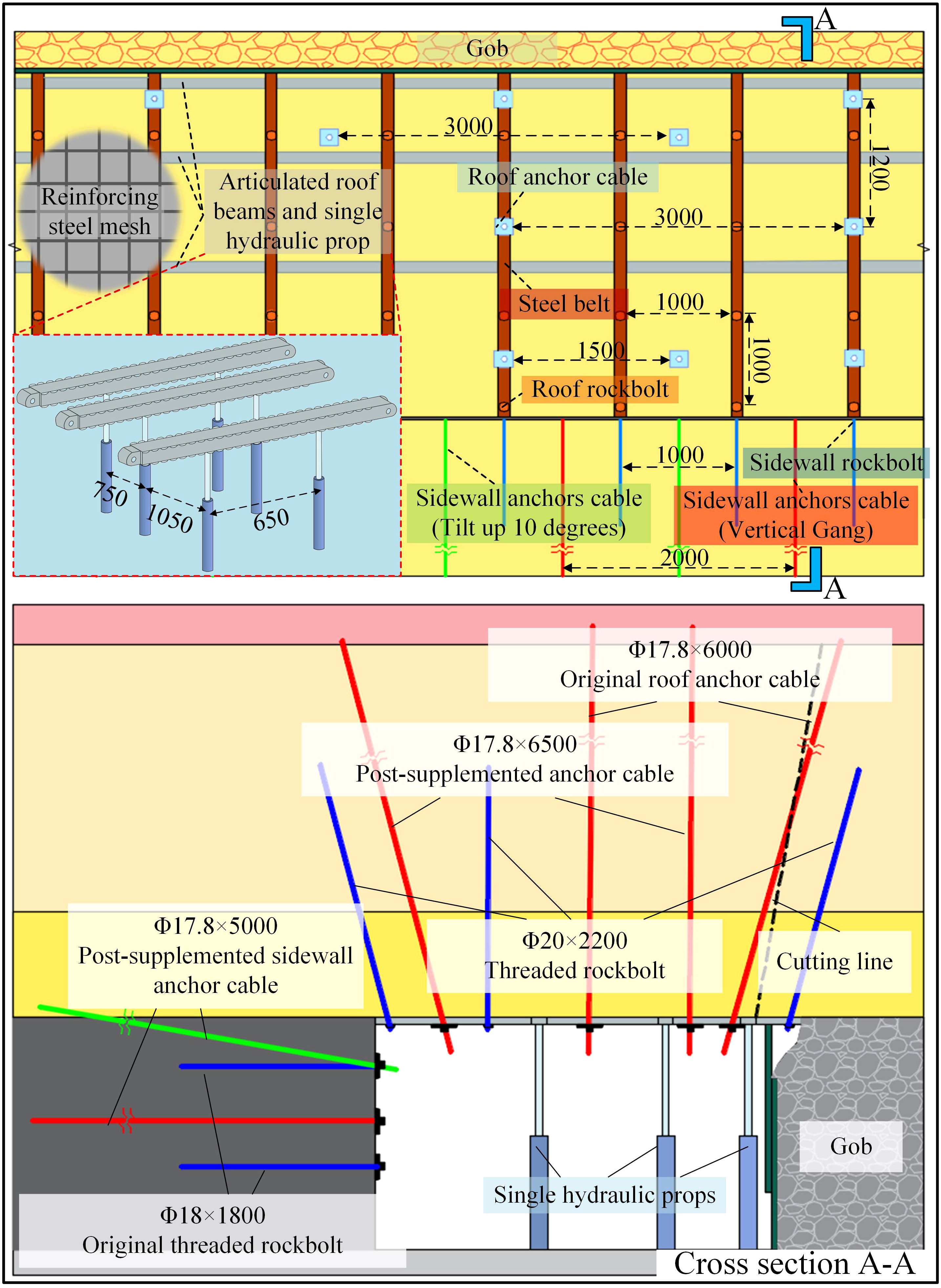
Figure 11 Support structure diagram (unit: mm).
To verify the theoretical calculations and simulation results, a field test was conducted. A KJ-24 wireless mine pressure monitoring system was used in the field for monitoring (Lou et al., 2021). The monitoring location diagram is shown in Figure 12. To better summarize the pressure changes of the retained roadway along the goaf roof, pressure gauges were installed on different single hydraulic props in the same cross-section. Real-time monitoring of the convergence of the roof and floor was conducted.
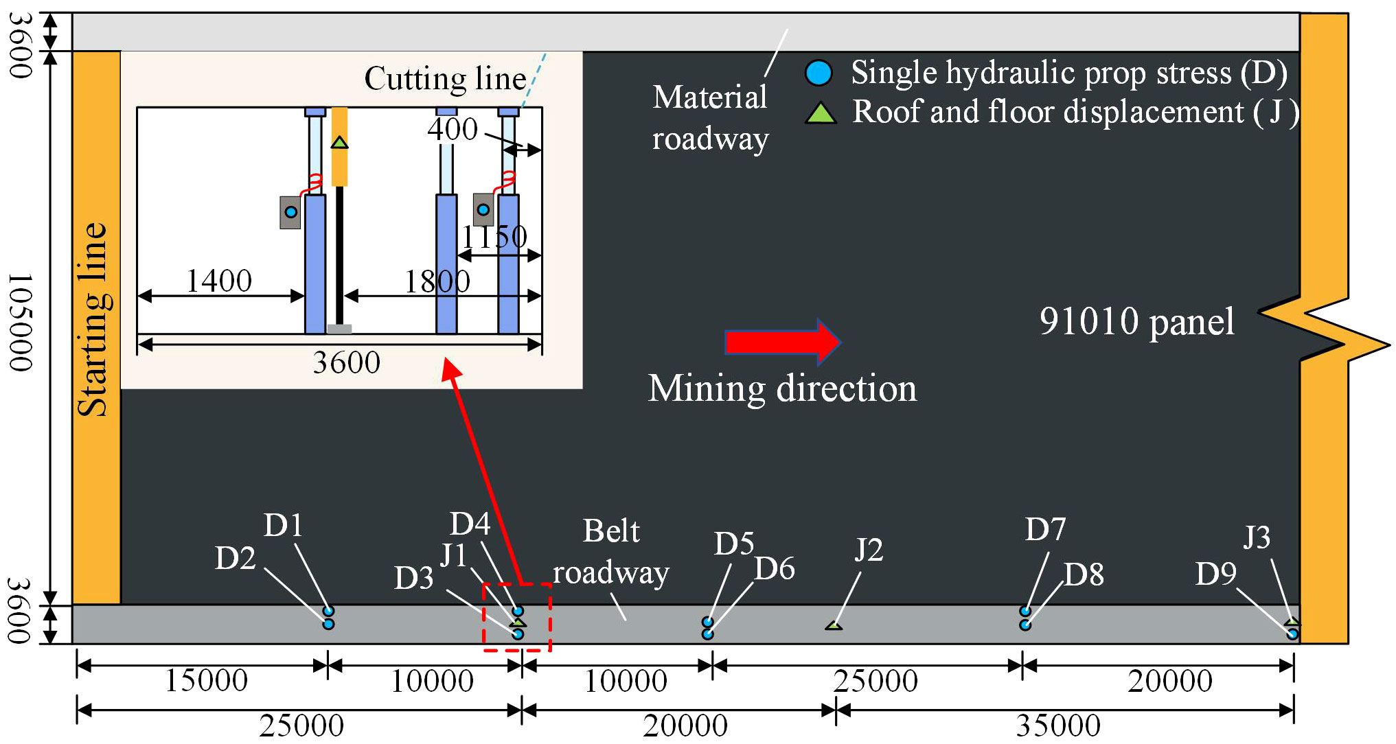
Figure 12 Roadway monitoring locations (unit: mm).
According to the vertical resistance monitoring data (Figure 13), the maximum value of the force of the three groups of single hydraulic props was stable at 126 kN, within the safety range, indicating that the support strength was sufficient. The force of the single hydraulic prop near the cutting line was always greater than that of the single hydraulic prop far from the cutting line, which verified the theoretical calculation result that the deflection of the cutting line side changes the most. The roof at D4 was more broken compared with other monitoring locations, and the single hydraulic prop pressure was the largest there.
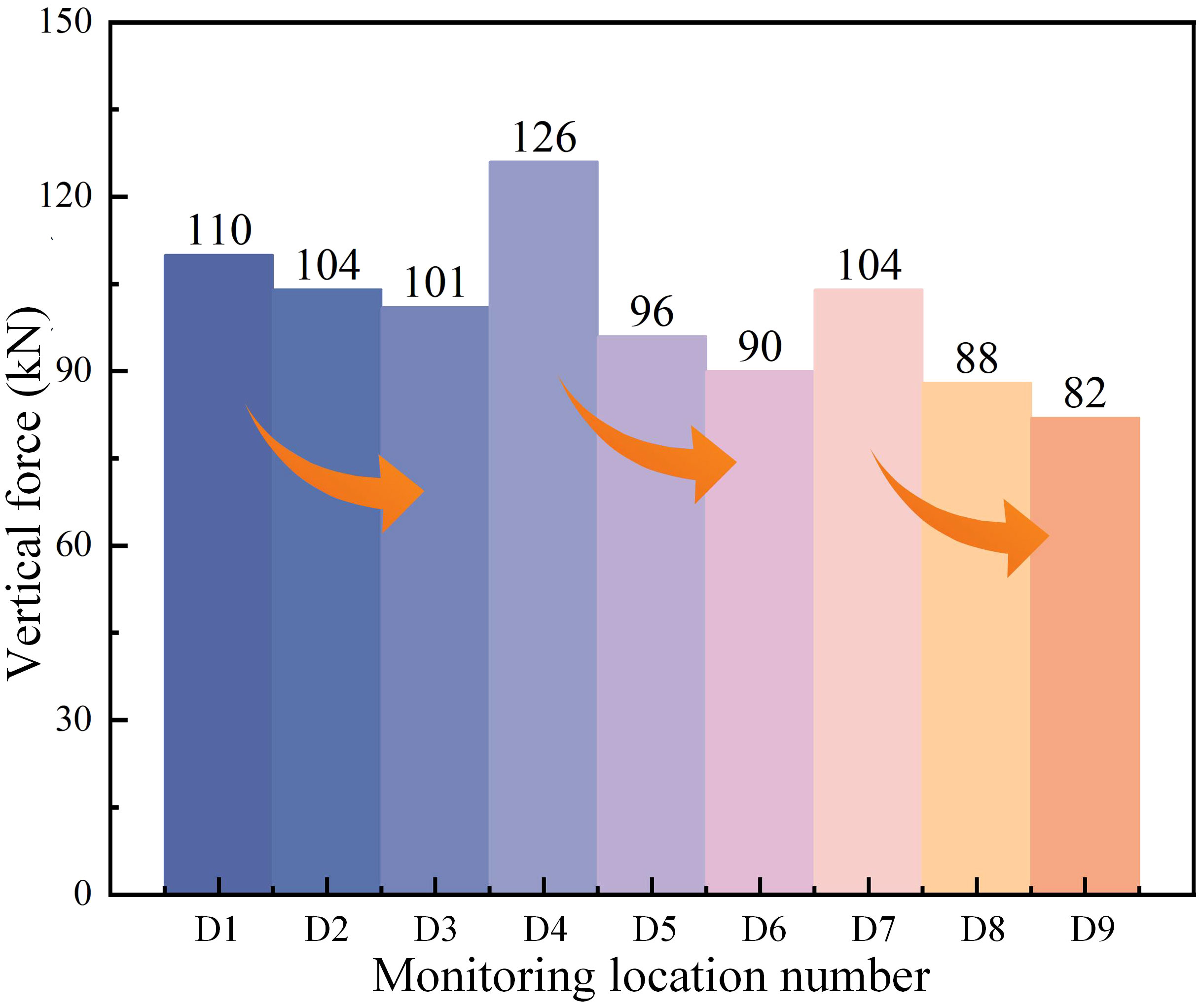
Figure 13 Histogram of the force of single hydraulic prop.
According to the data of the roof and floor displacement gauges (Figure 14), the convergence speed of the roof and floor started to accelerate approximately 20 m ahead of the panel. However, at this time, the amounts of roof and floor convergence were small. After the panel was pushed 25 m past the monitoring location, the convergence of the roof and floor reached the peak. Among them, due to the relatively poor condition of the roof at the J1 monitoring location, the roof and floor moved the most, reaching 99 mm: 50 mm and 55 mm were measured at J2 and J3, respectively, and the differences were 7 mm and 12 mm compared with the simulation results, which were within the safety range. In summary, the support strength was sufficient, and the surrounding rocks of the retained roadway were stable.
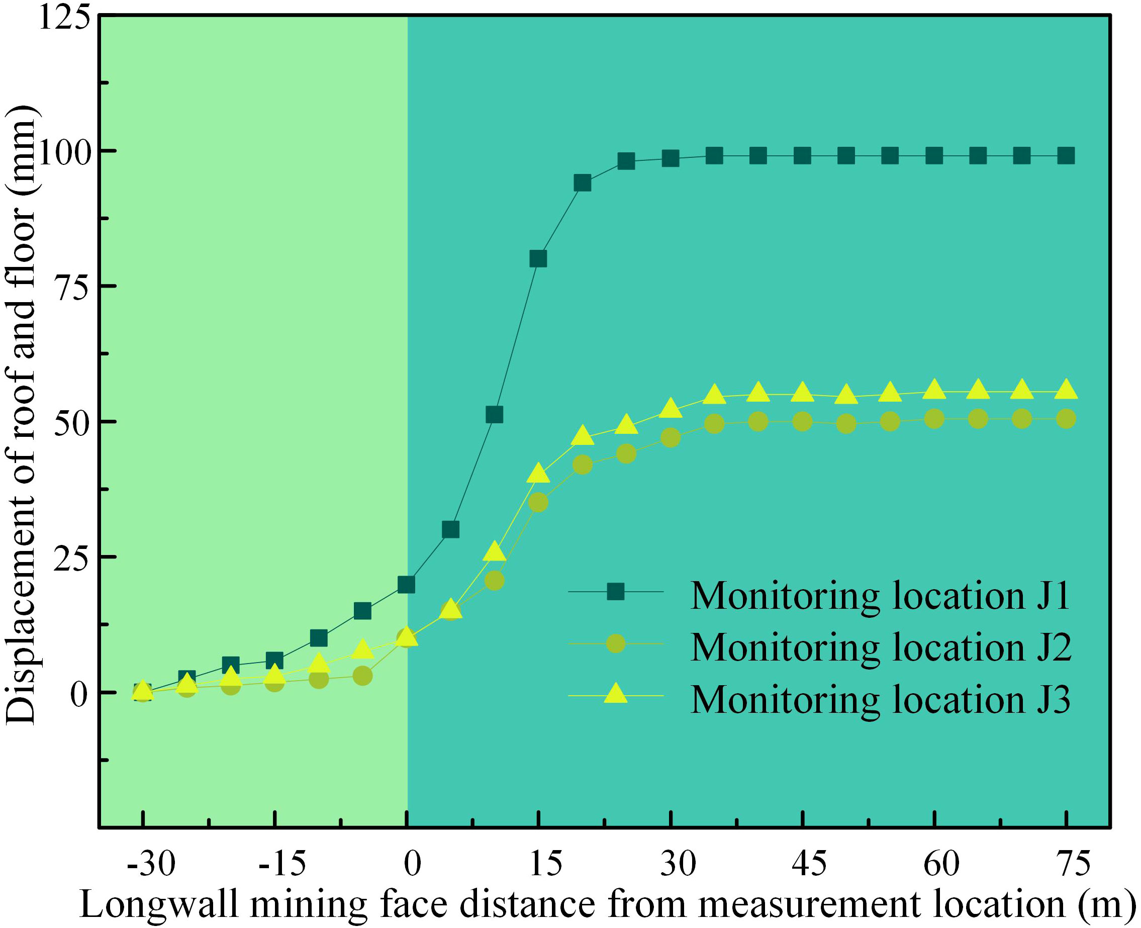
Figure 14 Roof and floor displacement.
Figure 15 shows the internal situation of the roadway roof after the mining panel had passed. Through a borehole camera, the roof of the K1-K3 section can be found to be still relatively intact, and there is no obvious increase in cracks on the roof. These results are consistent with the roof and floor displacement monitoring results, and the stability of the retained roadway roof is relatively high.
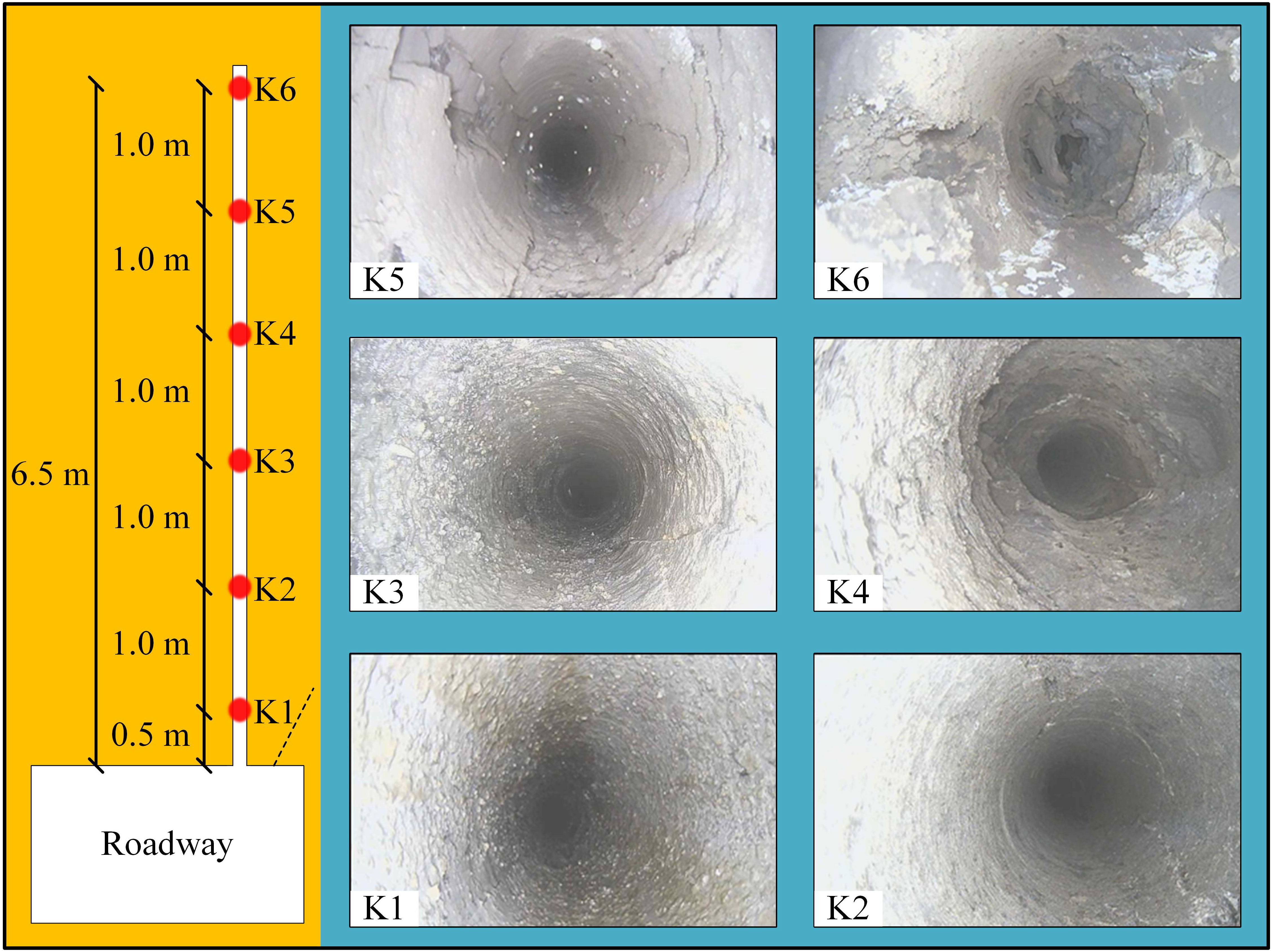
Figure 15 Internal conditions of the surrounding rock.
Through observation of the field situation, at 24-27 m from the beginning of the gob-side entry retaining, steel belt zigzagging and anchor net breaking occurred. This location was relatively close to the upper coal seam, resulting in a more broken roof and poor integrity. Compared to that of other areas, the deformation of the broken roof was greater, and the monitoring data also confirm this. Figure 16 shows the overall effect of the supported lane in the Xinchazhuang coal mine. Most of the roof of the roadway did not significantly deform, and the vertical support provided by the three rows of props effectively reduced the sinking amount of the roof.

Figure 16 Field support situation.
For the problem of roof control and support in the close coal seam retained roadway of the Xinchazhuang coal mine, a two-way verification method was adopted to solve the problem, as shown in Figure 17.

Figure 17 Two-way verification of roof control and support design ideas.
Various methods were used to study the failure characteristics of the rock between the close coal seams. Based on floor sliding theory, a preliminary calculation of the depth of rock failure development of the floor of the #8 coal seam was carried out, and it was concluded that the depth of floor sliding damage caused by #8 coal mining did not exceed the thickness of the rock between the two coal seams. The calculation results were further verified by a numerical simulation test, and the conclusion of the simulation test that an intact roof exists in the retained roadway was obtained. Finally, the actual field measurement of rock fragmentation characteristics verified the correctness of the previous research conclusions, and the field test conclusion of the existence of an intact rock layer in the roof of the gob-side entry retaining was obtained.
Based on the existence of an intact rock layer in the roof of the retained roadway, the preliminary roof control coupled support scheme of roof cutting + high-prestressed anchor cables + vertical support is formed. High-prestressed anchor cables anchor the roof and thus form a composite rock beam. The internal force solution of the corresponding composite rock beam calculation model was carried out to obtain the reasonable interrow spacing of anchor cables under the coupling factor support, and vertical support points were set for the hazard region. Numerical simulation tests were used to verify the effect of the coupled support scheme by comparison and validation. Finally, a field test was carried out in the Xinchazhuang coal mine to verify that the effect of the retained roadway was basically consistent with the research conclusion.
In addition, the author calculated the correlation between numerical simulation and field monitoring data through Pearson correlation coefficient (Edelmann et al., 2021). The results showed that there was a strong correlation between the two, indicating that the two can be verified each other.
The solution still has shortcomings. The simulation program did not consider the weaker roof condition and the weakening effect of roof cutting on the roof. Part of the roof in the early stage of the roadway was weakened by roof cutting, resulting in a large amount of sinking of the roof. In addition, the single hydraulic prop needs to be carried manually, and the individual support force is relatively small, which may be insufficient if the roof condition further deteriorates. Upgrading to a unit bracket may be considered at a later stage.
A comprehensive approach combining theoretical deduction, numerical simulation, and field test was used to systematically study roof control methods for close coal seam roadways. Theoretical deduction of the damage degree and internal stress distribution of the roof of the retaining roadway was conducted and verified through numerical simulation and field test. A targeted roof control scheme for close coal seam roadways was proposed.
(1) The roof of #9 coal seam still had intact rock layers under the influence of #8 coal seam mining. A computational model for the composite rock beam formed by using intact rock strata as the load-bearing structure and high-prestressed anchor cables to anchor the roof was established. Based on this calculation model, a formula for calculating the optimal spacing of anchor cables and the optimal arrangement points of vertical supports was derived.
(2) The numerical simulation results showed that roof cutting effectively reduced the stress of supporting structure and roof pressure, and the maximum stress of the anchor cable was reduced by 41 MPa after roof cutting. Through coupling support of high-prestressed anchor cables and vertical supports, the roof convergence was reduced by more than 49.1%.
(3) The field support plan of “roof cutting + high-prestressed anchor cables + single hydraulic props” was proposed. After implementation in the field, the maximum convergence of the roof was 99 mm, and the support forces were within the normal range. This study can provide reference for gob-side entry retaining in close distance coal seams without coal pillars under similar conditions.
The original contributions presented in the study are included in the article/supplementary material. Further inquiries can be directed to the corresponding author.
TL: Conceptualization, Funding acquisition, Methodology, Writing – review & editing. LY: Formal Analysis, Investigation, Visualization, Writing – original draft, Writing – review & editing. QZ: Validation, Writing – review & editing. DL: Data curation, Formal Analysis, Software, Writing – review & editing. YW: Data curation, Investigation, Resources, Writing – review & editing.
The author(s) declare financial support was received for the research, authorship, and/or publication of this article. This study was financially supported by the National Natural Science Foundation of China (No. 41772299) and the Natural Science Foundation of Shandong Province, China (No. ZR2023ME165).
The authors would like to thank the Shandong Key Laboratory of Civil Engineering Disaster Prevention and Mitigation (Shandong University of Science and Technology), National Natural Science Foundation of China and the Natural Science Foundation of Shandong Province for their support. We sincerely thank the editor, associate editor and reviewers for their critical evaluation and constructive suggestions, which helped to improve the manuscript.
The authors declare that the research was conducted in the absence of any commercial or financial relationships that could be construed as a potential conflict of interest.
All claims expressed in this article are solely those of the authors and do not necessarily represent those of their affiliated organizations, or those of the publisher, the editors and the reviewers. Any product that may be evaluated in this article, or claim that may be made by its manufacturer, is not guaranteed or endorsed by the publisher.
An Y. P., Zhang N., Zhao Y. M., Xie Z. Z. (2021). Field and numerical investigation on roof failure and fracture control of thick coal seam roadway. Eng. Fail. Anal. 128, 105594. doi: 10.1016/j.engfailanal.2021.105594
Chen D. D., Wu Y. Y., Xie S. R., Guo F. F., He F. L., Liu R. P. (2022). Reasonable location of stopping line in close-distance underlying coal seam and partition support of large cross-section roadway. Int. J. Coal Sci. Techn. 9, 55–77. doi: 10.1007/s40789-022-00528-7
Cheng G. W., Yang T. H., Liu H. Y., Wei L. K., Zhao Y., Liu Y. L., et al. (2020). Characteristics of stratum movement induced by downward longwall mining activities in middle-distance multi-seam. Int. J. Rock Mech. Min. 136, 104517. doi: 10.1016/j.ijrmms.2020.104517
Cheng H., Zhao H. B., Xu J. F., Qi F. Y., Zhang Y. X., Hu L. F. (2021b). Study on floor heave mechanism and control technology of roadway based on slip line field theory. J. Min. Sci. Tech. 6, 314–322. doi: 10.19606/j.cnki.jmst.2021.03.008
Cheng Z. H., Ma H. F., Sang C., Liu Y. Q. (2021a). Experimental research on dynamic evolution characteristics of roof movement and Mining-Induced stress of superimposed mining in a close distance coal seam group. Geotech. Geol. Eng. 39, 13–24. doi: 10.1007/s10706-019-00968-0
Edelmann D., Móri T. F., Székely G. J. (2021). On relationships between the Pearson and the distance correlation coefficients. Stat. Probabil. Lett. 169, 108960. doi: 10.1016/j.spl.2020.108960
He F. L., Lv K., Li X. B., Qin B. B., Li L. (2021). Failure mechanism and control of lower retracement channel in Close-Distance Double-Thick coal seams. Shock Vib. 2021, 1–19. doi: 10.1155/2021/6651099
Hu L. P., Zhang Y. J., Huang Z. F., Li Q. G., Wang H., Hu Z. F. (2023). Coal–rock dynamic disaster prevention mechanism based on the dual loads of dynamic barrier and static pressure relief by hydraulic slotting. ACS Omega 8, 7639–7647. doi: 10.1021/acsomega.2c07240
Jia C., Li S., Fan C. J., Luo M. K., Zhou L. J., Pu Z. A., et al. (2022). Bolt–cable–mesh integrated support technology for water drenching roadway in thick coal seam. ACS Omega 7, 46682–46692. doi: 10.1021/acsomega.2c05650
Kong D., Li Q., Wu G., Song G. (2021). Characteristics and control technology of face-end roof leaks subjected to repeated mining in close-distance coal seams. B. Eng. Geol. Environ. 80, 8363–8383. doi: 10.1007/s10064-021-02438-5
Li M., Zhang J. X., Huang P., Zhang Q., Wu Z. Y. (2021). Parameters updating and calibrated double-yield model methods to simulate the compaction behaviour of waste rock backfill materials in coal mine gob. Q. J. Eng. Geol. Hydroge. 55, qjegh2021–096. doi: 10.1144/qjegh2021-096
Li Q., Wu G. Y., Kong D. Z. (2022a). Study on stability of stope surrounding rock under repeated mining in close-distance coal seams. Geofluids 2022, 1–17. doi: 10.1155/2022/9630942
Li Q., Wu G. Y., Kong D. Z., Han S., Ma Z. Q. (2022b). Study on mechanism of end face roof leaks based on stope roof structure movement under repeated mining. Eng. Fail. Anal. 135, 106162. doi: 10.1016/j.engfailanal.2022.106162
Li T. C., Zhu Q. W., Lou Q. N., Zhang H., Ran J. L. (2023). Research on gob-side entry-retaining technology with coal rib and corner strengthened support in soft rock strata. Energy Sci. Eng. 11, 3597–3618. doi: 10.1002/ese3.1542
Li W. L., Tu S. H., Tu H. S., Li Y., Liu X., Miao K. J. (2022c). Failure characteristics and control techniques for mining roadway affected by stress accumulation of residual pillars in contiguous coal seams. Eng. Fail. Anal. 141, 106646. doi: 10.1016/j.engfailanal.2022.106646
Liu H. Y., Zhang B. Y., Li X. L., Liu C. W., Wang C., Wang F., et al. (2022a). Research on roof damage mechanism and control technology of gob-side entry retaining under close distance gob. Eng. Fail. Anal. 138, 106331. doi: 10.1016/j.engfailanal.2022.106331
Liu J., Lu P., Zhang L. W. (2022b). Influence of section shape and buried depth on rock loosening zone around underground roadway in coal mine. ACS Omega 7, 34296–34308. doi: 10.1021/acsomega.2c03811
Liu X. J., Li X. M., Pan W. D. (2016). Analysis on the floor stress distribution and roadway position in the close distance coal seams. Arab. J. Geosci. 9, 1–8. doi: 10.1007/s12517-015-2035-9
Lou Q. N., Li T. C., Zhu Q. W., Wu S. Y., Yun M., Zhao R. L. (2021). A control approach of the roof in No-Pillar roadway formed by roof cutting and pressure releasing. Geofluids 2021, 1–14. doi: 10.1155/2021/4303021
Lv K., He F. L., Li L., Xu X. H., Qin B. B. (2022). Field and simulation study of the rational retracement channel position and control strategy in close-distance coal seams. Energy Sci. Eng. 10, 2317–2332. doi: 10.1002/ese3.1140
Ning J. G., Wang J., Tan Y. L., Xu Q. (2020). Mechanical mechanism of overlying strata breaking and development of fractured zone during close-distance coal seam group mining. Int. J. Min. Sci. Techno. 30, 207–215. doi: 10.1016/j.ijmst.2019.03.001
Peng S. S., Du F., Cheng J. Y., Li Y. (2019). Automation in U.S. Longwall coal mining: A state-of-the-art review. Int. J. Min. Sci. Techno. 29, 151–159. doi: 10.1016/j.ijmst.2019.01.005
Qi Y., Wang W., Ge J. Q., Yang Z. B., Qi Q. J. (2022). Development characteristics of the rock fracture field in strata overlying a mined coal seam group. PloS One 17, e268955. doi: 10.1371/journal.pone.0268955
Qin Y., Xu N. X., Zhang Z. J., Zhang B. (2021). Failure process of rock strata due to multi-seam coal mining: Insights from physical modelling. Rock Mech. Rock Eng. 54, 2219–2232. doi: 10.1007/s00603-021-02415-0
Shang H. F., Ning J. G., Hu S. C., Yang S., Qiu P. Q. (2019). Field and numerical investigations of gateroad system failure under an irregular residual coal pillar in close-distance coal seams. Energy Sci. Eng. 7, 2720–2740. doi: 10.1002/ese3.455
Shang Y. Q., Zhang L., Kong D. Z., Wang Y., Cheng Z. B. (2023). Overlying strata failure mechanism and gas migration law in close distance outburst coal seams: A case study. Eng. Fail. Anal. 148, 107214. doi: 10.1016/j.engfailanal.2023.107214
Suchowerska A. M., Merifield R. S., Carter J. P. (2013). Vertical stress changes in multi-seam mining under supercritical longwall panels. Int. J. Rock Mech. Min. 61, 306–320. doi: 10.1016/j.ijrmms.2013.02.009
Sun B. J., Liu Q. W., Li W. T., Yang X. Z., Yang B., Li T. C. (2022). Numerical implementation of rock bolts with yield and fracture behaviour under tensile-shear load. Eng. Fail. Anal. 139, 106462. doi: 10.1016/j.engfailanal.2022.106462
Sun X. Y., Lu M. J., Li C. (2021). Optimization of staggered distance of coal pillars in multiseam mining: Theoretical analysis and numerical simulation. Energy Sci. Eng. 9, 357–374. doi: 10.1002/ese3.824
Tan Y. L., Ma Q., Zhao Z. H., Gu Q. H., Fan D. Y., Song S. L., et al. (2019). Cooperative bearing behaviors of roadside support and surrounding rocks along gob-side. Geomech. Eng. 4, 439–448. doi: 10.12989/gae.2019.18.4.439
Tao Z. G., Song Z. G., He M. C., Meng Z. G., Pang S. H. (2018). Principles of the roof cut short-arm beam mining method (110 method) and its mining-induced stress distribution. Int. J. Min. Sci. Techno. 28, 391–396. doi: 10.1016/j.ijmst.2017.09.002
Tian C. L., Liu Y. B., Yang X. L., Hu Q. T., Wang B., Yang H. M. (2020). Development characteristics and field detection of overburden fracture zone in multiseam mining: A case study. Energy Sci. Eng. 8, 602–615. doi: 10.1002/ese3.536
Wang J. C., Wang Z. H. (2019). Systematic principles of surrounding rock control in longwall mining within thick coal seams. Int. J. Min. Sci. Techno. 29, 65–71. doi: 10.1016/j.ijmst.2018.11.014
Wang Q., Xu S., Xin Z. X., He M. C., Wei H. Y., Jiang B. (2022). Mechanical properties and field application of constant resistance energy-absorbing anchor cable. Tunn. Undergr. Sp. Tech. 125, 104526. doi: 10.1016/j.tust.2022.104526
Wang Y. W., Yuan H. H., Gao M. Z., Li M. H., Sun J. G. (2023). Fracture law of different overlying strata in mining of protective seam under close distance coal seam. Energy Sci. Eng. 11, 1336–1348. doi: 10.1002/ese3.1396
Yan B. Q., Che S. J., Tannant D. D., Ren F. H., Wang P. T. (2019). Application of double-yield model in numerical simulation of stability of mining filling body. Arab. J. Geosci. 12, 515–535. doi: 10.1007/s12517-019-4679-3
Yan H., Weng M., Feng R., Li W. (2015). Layout and support design of a coal roadway in ultra-close multiple-seams. J. Cent. South Univ. 22, 4385–4395. doi: 10.1007/s11771-015-2987-7
Yu Y. H., Ma L. Q., Zhang D. S., Su F. Q., Wang G. Y. (2022). Approach for numerical modeling of Strain-Hardening materials using Double-Yield model. Rock Mech. Rock Eng. 55, 7357–7367. doi: 10.1007/s00603-022-02883-y
Zhang F. D., Gao Z. N., Meng X. R. (2012). Study on the distribution of plastic zone and damage mechanism of quarry floor. CSTA. 29, 59–61. doi: 10.3969/j.issn.1001-5485.2012.11.013
Zhang H. L., Cao J. J., Tu M. (2013). Floor stress evolution laws and its effect on stability of floor roadway. Int. J. Min. Sci. Techno. 23, 631–636. doi: 10.1016/j.ijmst.2013.08.002
Zhang Q. Y., Ren M. Y., Duan K., Wang W. S., Gao Q., Lin H. X., et al. (2019). Geo-mechanical model test on the collaborative bearing effect of rock-support system for deep tunnel in complicated rock strata. Tunn. Undergr. Sp. Tech. 91, 103001. doi: 10.1016/j.tust.2019.103001
Zhang Z. Z., Deng M., Bai J. B., Yan S., Yu X. Y. (2021). Stability control of gob-side entry retained under the gob with close distance coal seams. Int. J. Min. Sci. Techno. 31, 321–332. doi: 10.1016/j.ijmst.2020.11.002
Zhao H. B., Cheng H., Ji D. L., Wang T., Wang Y. K., Jiang C. B. (2021). Study of the mechanism and evolution law of unsymmetrical failure of the mining roadway in close distance coal seam. J. China Univ. Min. Technol. 50, 1029–1040. doi: 10.13247/j.cnki.jcumt.001342
Zhao H. B., Cheng H., Li J. Y., Wang T., Liu Y. H., QI F. Y. (2020). Study on asymmetric deformation mechanism of surrounding rock of roadway under the effect of isolated coal pillar. Chin. J. Rock Mech. Eng. 39, 2771–2784. doi: 10.13722/j.cnki.jrme.2019.0934
Zhu Q. W., Li T. C., Wang B. X., Li C. J., Ran J. L., Zhang H. (2023). A case study on the deformation and failure mechanism of a soft rock mining roadway in the Xin’Shang’Hai No. 1 coal mine, China. Eng. Fail. Anal. 146, 107136. doi: 10.1016/j.engfailanal.2023.107136
Some intermediate variables omitted in Section 3.2 are listed in this section to satisfy the requirement of solving for the optimal interrow spacing of anchor cables.
The internal stress components of the composite rock beam under a uniform load and simply supported conditions are:
Under gangue support, the internal stress components of the composite rock beam are:
The internal stress components of the composite rock beam supported by a single hydraulic prop strut are:
Under the action of the high-prestressed anchor cable, the internal stress components of the composite rock beam are:
where J1, J2, J3, σx4, σy4 and τxy4 are:
The anchor cable support strength formula is:
Keywords: close coal seam roadway, characteristics of roof failure, surrounding rock control, coupled support design, numerical simulation
Citation: Li T, Yang L, Zhu Q, Liu D and Wang Y (2023) Research on the coupled support technology of a composite rock beam-retained roadway roof under close coal seams. Front. Ecol. Evol. 11:1291359. doi: 10.3389/fevo.2023.1291359
Received: 09 September 2023; Accepted: 17 October 2023;
Published: 31 October 2023.
Edited by:
Yongqiang Zhou, Chinese Academy of Sciences (CAS), ChinaReviewed by:
Chun Zhu, Hohai University, ChinaCopyright © 2023 Li, Yang, Zhu, Liu and Wang. This is an open-access article distributed under the terms of the Creative Commons Attribution License (CC BY). The use, distribution or reproduction in other forums is permitted, provided the original author(s) and the copyright owner(s) are credited and that the original publication in this journal is cited, in accordance with accepted academic practice. No use, distribution or reproduction is permitted which does not comply with these terms.
*Correspondence: Qingwen Zhu, emh1cXdAc2R1c3QuZWR1LmNu
Disclaimer: All claims expressed in this article are solely those of the authors and do not necessarily represent those of their affiliated organizations, or those of the publisher, the editors and the reviewers. Any product that may be evaluated in this article or claim that may be made by its manufacturer is not guaranteed or endorsed by the publisher.
Research integrity at Frontiers
Learn more about the work of our research integrity team to safeguard the quality of each article we publish.