 Juntao Liu1
 Wenlong Shen
94% of researchers rate our articles as excellent or good
Learn more about the work of our research integrity team to safeguard the quality of each article we publish.
Find out more
ORIGINAL RESEARCH article
Front. Ecol. Evol., 07 September 2023
Sec. Environmental Informatics and Remote Sensing
Volume 11 - 2023 | https://doi.org/10.3389/fevo.2023.1265883
This article is part of the Research TopicCoal and Rock Dynamic Disasters: Advances of Physical and Numerical Simulation in Monitoring, Early Warning, and Prevention, volume IIView all 29 articles
Longwall entrance is especially vulnerable to the combined mining of nearby coal seams because of the substantial deformation disaster loaded by the abutment stress caused by the mining disturbance. Changes to the fracture characteristics, movement behavior, and structural morphology of the bearing structure above the coal pillar are recommended using the separated layer rock failure technology (SLRFT) to safeguard the entry beneath the coal pillar from high abutment stress. To simulate the impacts of the SLRFT on the decrease of the abutment stress surrounding the entry under the coal pillar under the plane–stress circumstances, two experimental models were created. Abutment stress revolution, roof movement laws, and fracture features were all tracked using three identical monitoring systems in each experimental model. The experimental results indicate that SLRFT generates the shorter caving step length, more layered collapse, and higher caving height of the immediate roof, which improves the dilatancy of caving rock mass, the filling rate, and the compaction degree of the worked-out area. In the ceiling above the worked-out area, the fracture progresses from a non-penetrating horizontal and oblique gaping fracture to stepped closed fractures and piercing fractures. The main roof’s subsidence shifts from a linear, slow tendency to a stepped, fast one. The bearing structure changes from two-side cantilever structure with a T type into one-side cantilever structure with a basin type. Because the compacted worked-out region has a bigger support area, more of the overburden load is transferred there, weakening the abutment stress around the longwall entry from 12.5 kPa to 3.7 kPa. The stress reduction degree increases with the reduction of the cantilever length of the bearing structure and the increasing of the support coefficient of the compacted worked-out area. These findings illustrate the effectiveness of SLRFT in lowering entrance stress. With the established experimental model, it is possible to evaluate the viability, efficiency, and design of SLRFT under various engineering and geological circumstances.
The stability of the longwall entry is affected by the stress, the materials, and the support surrounding it (Kang et al., 2019; Xia et al., 2022; Li et al., 2023; Zhang et al., 2023a). The longwall entry will serve as the subterranean space’s access point for ventilation, transit, pedestrian, and other production systems. It will encounter multiple disturbances of the mining abutment stress when it is located under the coal pillar in the combined mining of close distance coal seams (Ning et al., 2020). According to Liu et al. (2021), these multiple disturbances will result in supporting body failure, significant deformation, roof collapsing, or even rock burst, endangering the stability control of the longwall entry under a specific geological and technical condition. These specific geological and technical conditions always concentrate on temperature, air pressure, hydraulic pressure, and the ground pressure (Liu and Li, 2023; Liu et al., 2023b; Ye et al., 2023; Zhang et al., 2023b). According to Zhang et al. (2022b), locating the abutment stress’s origin is helpful for stress reduction.
According to Wang et al. (2015), the abutment stress in the upper close-distance coal pillar is the main source of the abutment stress near the longwall entry. When the neighboring working face retreats, this coal pillar will experience loading and unloading action, which alters how the abutment stress is distributed in the coal pillar (Shen et al., 2016). This change is induced from the partial overburden weight above the worked-out area loading on the unworked-out area by the bearing structure, which results in the stress redistribution around the longwall entry under the coal pillar and makes the rock around the longwall entry suffer from loading and unloading action either (Shen et al., 2021; Zhang et al., 2023c). Under this type of action, the plastic, crushing, and rupture failure zones will spread into the deeper rock surrounding the longwall entry, which is the cause of the longwall entry’s significant deformation (Bai et al., 2015; Liu et al., 2023a; Zhang et al., 2020; Liu et al., 2022). To lessen the failure zone indicated above and keep this longwall entrance stable, it is effective to weaken the abutment stress.
To reduce abutment stress, one can either eliminate the source of the stress, avoid situations with high abutment stress, or move the stress to a location remote from the longwall entry (Shen et al., 2020). Solid backfilling technology is used to eliminate the generation of the abutment stress by preventing the movement of the roofs, which needs to consume a lot of filling materials and is hard to reach 100% of filling rate (Zhang et al., 2016; Zhang et al., 2022c; Meng et al., 2023). When the location of the longwall entry is permissible for adjustment (Wilson and Ashwin, 1972; Hou and Ma, 1989; Li et al., 2015; Yuan et al., 2023), entry layout technology can protect the longwall entry from high abutment stress. Cutting roof technology can transfer the abutment stress from the longwall entry to the far away area by changing the bearing structure above the coal pillar, which always ignores the effects of the nearby thick rock strata’s movement, the upper hard roof structure movement, the structure plane along the rock plane, and the preset crack mechanical behavior (Huang et al., 2018; Wang et al., 2021; Wang et al., 2020; Sun et al., 2022; Zhang et al., 2022a). It is necessary to conduct more research to determine whether the hard roof would crack, slip, cave along the predicted crack plane, and produce a suitable bearing structure above the coal pillar.
In this work, separated layer rock failure technology (SLRFT) is proposed to weaken the multiple disturbances of the abutment stress and improve the stability of the longwall entry. The initial step in determining its stress reduction method is to analyze the fracture characteristics, movement behavior, and structural morphology of the bearing structure above the coal pillar. For the purpose of revealing the process for stress reduction and subsequently proving the viability of SLRFT, two physical simulation models with plane–stress circumstances are created. SLRFT’s effectiveness and influencing elements are ultimately explored and determined.
A technique for altering rock structure while mining disturbs it is shown in Figure 1. It is known as SLRFT. The artificial structure plane parallel to the lower thick rock stratum plane (ASPP), the artificial structure plane intersecting in the upper thick hard roof (ASPI), and the mining extra loading and unloading impact on ASPP and ASPI (MALU) make up its three interaction aspects. In the SLRFT, ASPP is an artificial discontinuous structural plane that needs to be parallel to the thick rock stratum plane and can be generated with hydrofracturing or high-pressure water jet technology in the field application. Its main function is accelerating the movement of lower thick rock strata by separating the lower thick rock strata into multiple straticulate rock structures along ASPP under MALU. By dividing the upper thick hard roof into two portions along ASPI under MALU, ASPI plays a crucial function in identifying the site of the fracture of the upper thick hard roof. MALU is experiencing temporal and spatial variation during the ASPP and ASPI processes. In addition, the time-varying MALU will respond to the ASPP and ASPI processes. Finally, SLRFT will achieve the reduction of abutment stress around the longwall entry by changing the bearing structure of the fracture thick roof strata with ASPP, ASPI, and MALU.
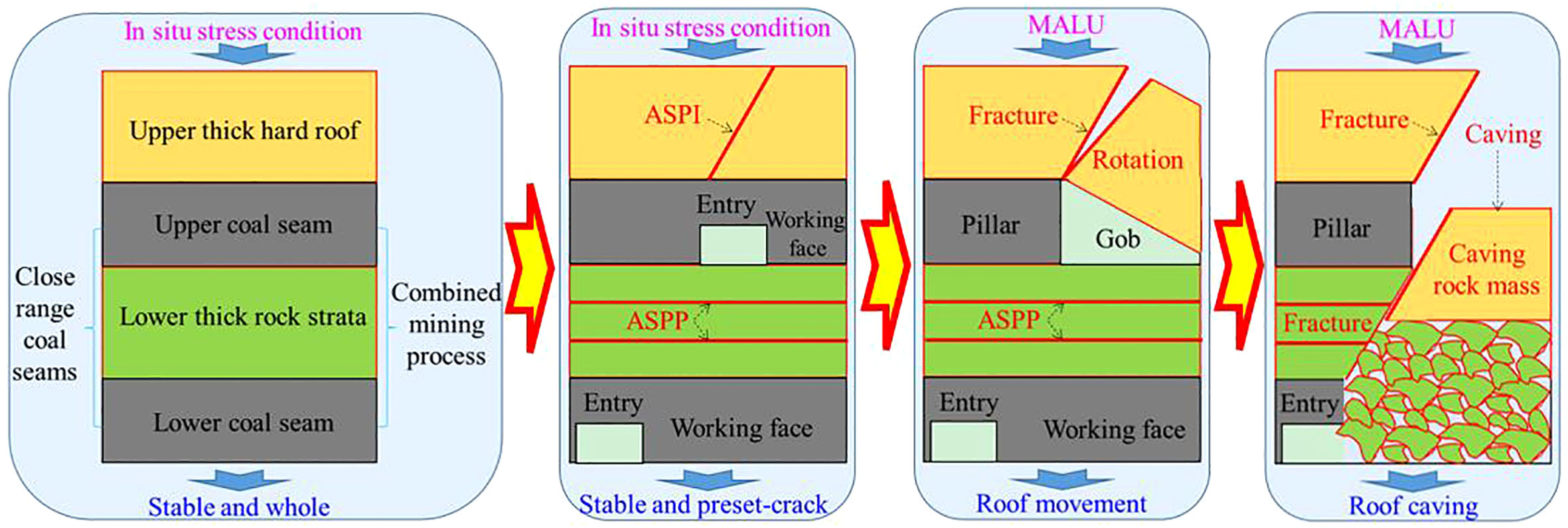
Figure 1 Method of SLRFT.
Before MALU and ASPP may have an impact, ASPI must be created in the upper thick hard roof. Under the first in-place load, the hard roof maintains its stability and completeness. The hard roof’s internal load will transform into a new equilibrium state after ASPI is created, whereas the hard roof’s external load will remain in its initial state. The exterior load of the hard roof will change into a different state during the MALU process due to the mining impact; thus, it maintains stability because the internal change cannot affect the external condition. When the worked-out area is covered by the hard roof, this external load will decrease. However, it will rise if the neighboring undeveloped area is covered by a hard roof. In addition, as the mining working face advances, it will go through a rising and decreasing procedure. Finally, with the influence of MALU, the hard roof will fracture along the preset structure plane and changes into a reasonable bearing structure by a different way of movement behavior and fracture characteristics.
Prior to the impact of MALU, ASPP must be created in the lower, thicker rock strata. The thick rock strata maintain their stability under the initial in situ stress before the influence of MALU. After ASPP is established, it is separated into multiple straticulate rock structures. The straticulate rock structures are susceptible to bending, fracturing, caving, and expanding under the impact of MALU. The thick rock strata’s movement behavior, fracture characteristics, and structural morphology will alter as a result of ASPP. Finally, the caving-expansion rock mass is beneficial to the filling of the underground mined area, which will affect the behavior of the upper thick hard roof
In the Chinese province of Shanxi, Jinzhong is home to the Lingshihuayuan coal mine. In this coal mine, the nearby coal seams are mined using a combined mining technique to provide coal resources. The coal seams at numbers 8, 9, 10, and 11 are the closest to the surface as shown in Figure 2A. Among the coal seams, the thickness of the numbers 8 and 11 cannot meet the mining requirement under the current mining technology. Nearly 390 m below the surface of the earth, there is a coal seam known as number 9. Its average thickness is 1.12 m, and its average dip angle is 2°. Limestone, sandstone, and fine sandstone make up the underlying strata above coal seam number 9. Moreover, the roof strata of the number 10 coal seam are composed of sandy mudstone, which is located beneath the number 9 coal seam. This roof strata’s average thickness is 5.32 m, which corresponds to the distance between coal seam numbers 9 and 10. The number 10 coal seam has an average thickness of 4.23 m and a 2° dip angle. Sandstone, the number 11 coal seam, mudstone, and sandstone are among the geological types found in its nether regions.
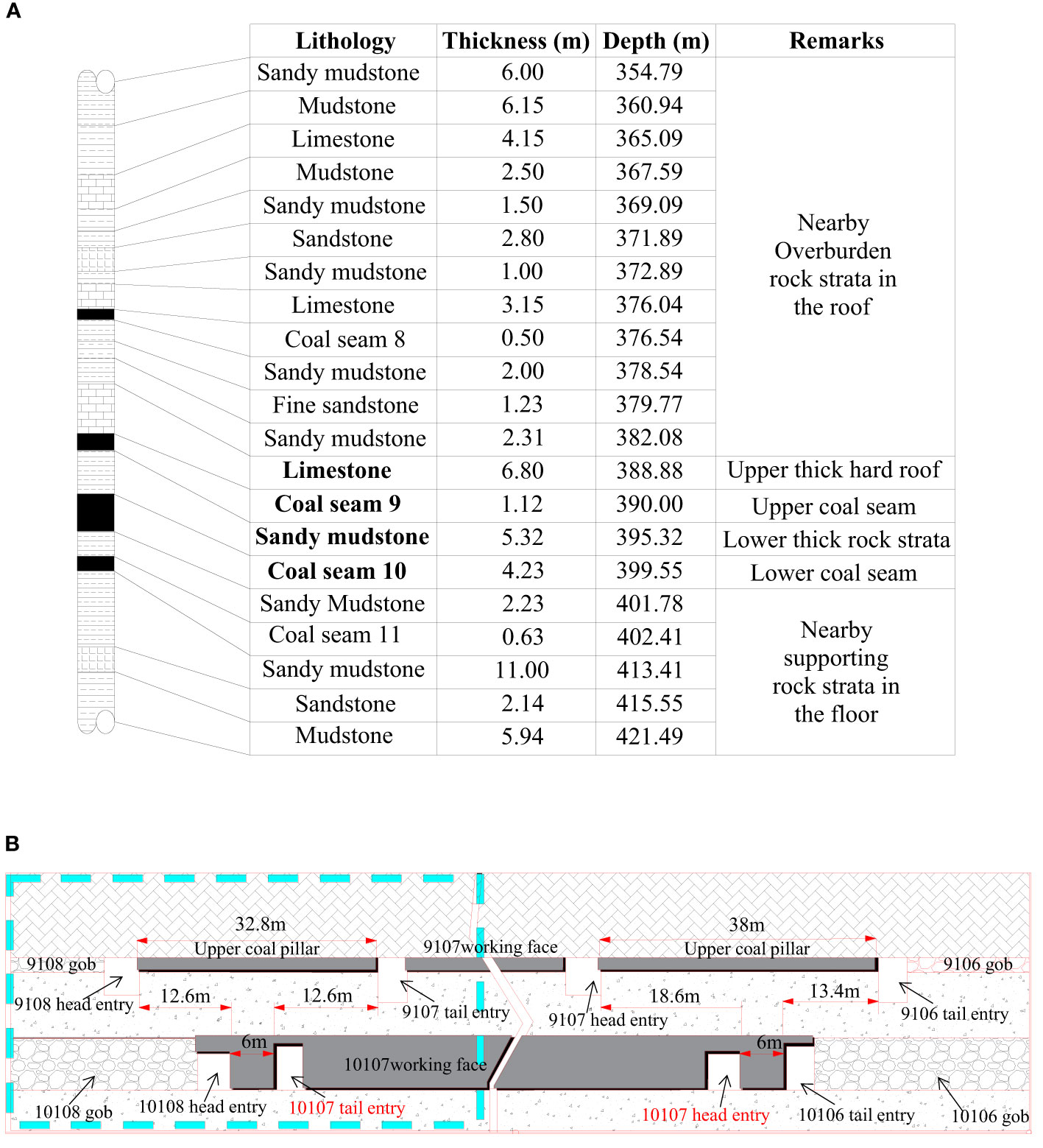
Figure 2 Generalized stratigraphic column and entry layout condition. (A) Coal seam histogram. (B) Entry layout profile.
Each coal seam uses a two-entry method, as indicated in Figure 2B, for every longwall full-seam operation. The length of the longwall panel is 164 m in the coal seam number 9 and 199 m in coal seam number 10. To recycle more than 378,872 tons of coal resources, the entry of the longwall panel in coal seam number 10 must be positioned below the coal pillar of the longwall panel in coal seam number 9. The entry must be made to withstand the abutment stress brought on by the upper coal pillar and mining working face in coal seam numbers 9 and 10.
As illustrated in Figure 3, two physical models were developed to assess the SLRFT’s reliability at the State Key Laboratory of Coal Resources in China. Each model has a length, a width, and a height of 2.50 m, 0.20 m, and 0.73 m, respectively. The shape, density, and strength should be consistent with the connection as Equation (1), according to the similarity theory (Fumagalli, 1973). In this experiment, CL, Cρ, Cσ, and Ct’s similarity ratios were calculated to be 100, 1.5, 150, and 10, respectively. With the help of this model design, it is possible to simulate the mechanical behavior of the higher coal pillar and lower entry and lower mining operating activities in the lower coal seam. To replicate the SLRFT effects in the two models, various ASPP and ASPI numbers were set up. In model 1’s sandy mudstone, one ASPP was placed in the center, and, in model 2’s sandy mudstone, two ASPPs were placed, as shown in Figure 3. In addition, two ASPIs were placed in the limestone in model 2, whereas zero ASPIs were placed in model 1, as seen in Figure 3.

Figure 3 Physical models for SLRFT. (A) Model 1 with ASPP and without ASPI. (B) Model 2 with ASPP and ASPI.
where CL, Cσ, and Ct are the similarity ratios of geometry, strength, and time, respectively. Cρ is the density similarity ratio between the prototype and the model. Lp, σp, and ρp represent the dimension, strength, and density of the rock strata in the field, respectively; Lm, σm, and ρm represent the dimension, strength, and density of the rock strata in the model, respectively.
Table 1 lists the 21 materials that were utilized to mimic the mechanical behavior of rock strata, coal seams, ASPP, ASPI, and structure plane for each model. Sand, gypsum, calcium carbonate, water, mica powder, and other materials are mixed together. According to the strength similarity ratio and the uniaxial compression strength of each rock stratum, the ratio of each type of simulation material contents is established by the current material ratio (Tu, 2010). For each model, a total of 809.64 kg of sand, 61.09 kg of calcium carbonate, 115.75 kg of gypsum, 98.6 L of water, and 20 kg of mica powder are utilized.
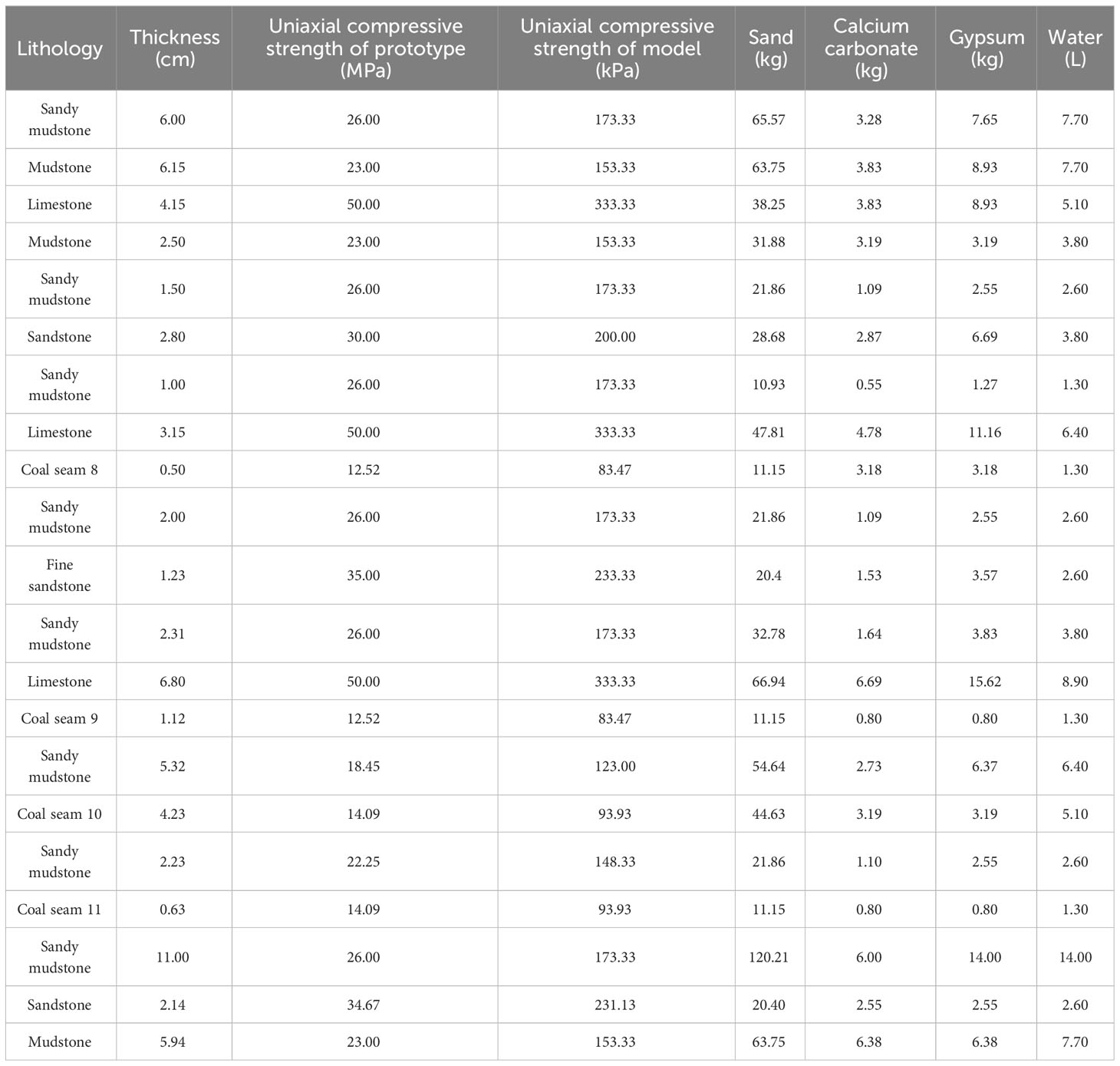
Table 1 Materials used in each physical model.
Evaluating the indices of the SLRFT effect during the combined mining activity of upper and lower working faces, the vertical displacement, structure morphology, and abutment stress are identified. To track the development of the abutment stress in the rock at the longwall entry, a ZC40YL data acquisition system with a BW flat earth pressure box was used. The progression of the vertical displacement was documented using a three-dimensional digital photogrammetry system called CoordMeasis that included white gauge points, encoding points, and scale plates. The structure morphology was also captured using the high-definition camera. In the physical model, 189 gauge points and six flat earth pressure boxes are placed. According to Figure 4, the specific monitoring settings are set up.
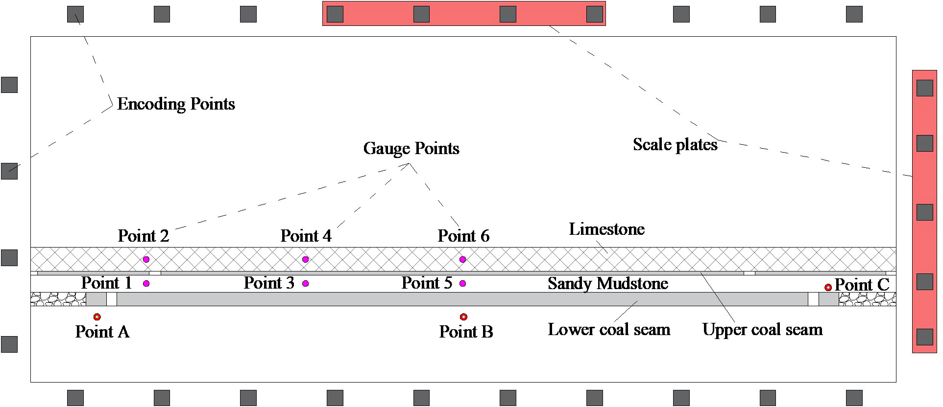
Figure 4 Monitoring points layout in the physical models.
The sandy mudstone above the lower coal seam and the limestone above the upper coal seam are chosen as the focus of the analysis to highlight the impacts of SLRFT on the vertical displacement. Six monitoring locations have been chosen in total to track the limestone and sandstone’s vertical displacement over time. Points 1 and 2 are situated at the sandy mudstone and limestone, respectively, and are separated from the lower coal seam’s lateral end of the gob by a horizontal distance of 11.5 cm. At a horizontal distance of 57.5 cm from the lateral termination of the gob in the lower coal seam, points 3 and 4 are situated at the sandy mudstone and limestone, respectively. With a horizontal distance of 102.9 cm from the lateral endpoint of the gob in the lower coal seam, points 5 and 6 are situated at the sandy mudstone and limestone, respectively.
The sandstone above the lower coal seam and the sandstone below the lower coal seam are chosen to study the bearing properties of rock strata beneath the upper coal pillar to reveal the impacts of SLRFT on the abutment stress. Three monitoring locations have been chosen in total to track the development of the rock below the top coal pillar’s abutment stress. Underneath the lower coal pillar, at point A, is the sandy mudstone. The location of point B is at the sandy mudstone beneath the center of the lower working face. Above the lower coal pillar, point C is situated at the sandy mudstone.
Seven steps make up the entire experimental process. The first phase involves setting up the experimental equipment and supplies. The two tall, stiff loading frames, the electricity-powered mixing barrel, the electronic scale, the monitoring systems, the simulation materials, and other necessary equipment are among them. For each model, 21 actual rock strata can be built individually in the second stage. A variety of mica powders were employed to replicate ASPP in the sandy mudstone, ASPI in the limestone, and the structural plane between two neighboring rock strata. In the third step, 20 loading rams in the top frame were subjected to a vertical load of 0.06 MPa to approximate the overburden loads after 1 week. The normal displacement in the floor and side boundaries was fixed with the frame. In the fourth step, excavation was conducted to generate the entries, coal pillars, gobs, and working faces in the upper and lower coal seams under the condition of the design in Figure 2. The order of excavation in the upper coal seam is as follows: 9106 tail entry, 9106 gob, 9108 head entry, 9108 gob, 9107 head entry, and 9107 tail entry. The lower coal seam has the following order: 10107 head entry, 10107 tail entry, 10108 head entry, 10108 gob, 10106 tail entry, 10106 gob, and 10108 head entry. The working face was retreated in the fifth step, moving from the upper coal seam’s 9107 head entry to 9107 tail entry stage by stage every 30 min. A miniature shovel was used in each stage to dig out coal that was 10 mm long. After the working face had been excavated by 50 cm in the higher coal seam, the working face was retreated from 10107 head entrance to 10107 tail entry stage by stage every 30 min in the lower coal seam. The distance between the bottom and upper working faces, measured horizontally, is 50 cm. A small shovel was also used at each stage to dig out coal that was 10 mm long. The excavation continues through the final working face in the lower coal seam in the final stage. The monitoring systems should be functioning normally during excavation so that they can record data until the completion of excavation.
In the experimental procedures, the mining activities are divided into three stages: stage I, stage II, and stage III. The upper working face is retreating in stage I, whereas the lower working face remains stationary. Once the upper working face has retreated 50 cm, the lower working face also starts to regress, and the mining operation shifts to stage II, which is a simultaneous retreat of the upper and lower working faces. After the top working face retreats to the finishing line position, 150 cm from the start, the mining activity transitions into stage III, which involves the retreating of the bottom working face.
SLRFT primarily accelerates the roof subsidence close to the lateral gob termination in the lower coal seam, as seen in Figure 5A. In stage I, roof sinking at point 1 remains at zero, whereas it steadily increases at point 2 as the top working face retreats. In this stage, there is little and a gradual increase in the subsidence difference between the SLRFT effect and the ASPP effect. As the upper and lower working faces combine to retreat, roof sinking at point 1 grows gradually in stage II, then accelerates quickly later, and eventually stabilizes gradually. The end value that SLRFT has an impact on is almost the same as the final value that ASPP has an impact on, and the velocity that SLRFT has an impact on is greater than that of ASPP. More definitely, the combined retreating of the upper and lower working faces is indicated by the roof sinking of point 2 increasing slowly with a linear trend under the impact of ASPP and increasing slowly under the influence of SLRFT. Its final value and velocity influenced by SLRFT are significantly larger than them influenced by ASPP. Because the lower working face is receding in stage III, roof subsidence at points 1 and 2 remains steady and barely changes. This suggests that stage II is when SLRFT and ASPP have the most impact on roof subsidence.
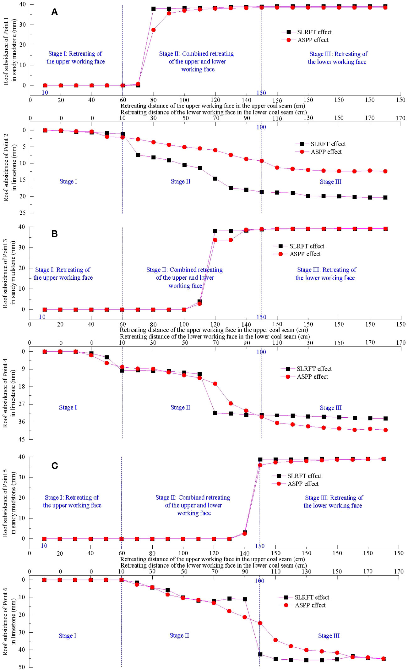
Figure 5 Movement behavior of roofs influenced by SLRFT and ASPP. (A) Roofs above the position 11.5 cm away from the lateral end of gob in the lower coal seam. (B) Roofs above the position 57.5 cm away from the lateral end of gob in the lower coal seam. (C) Roofs above the position 102.9 cm away from the lateral end of gob in the lower coal seam.
As depicted in Figure 5B, SLRFT mostly contributes to the acceleration of roof sinking toward the location 57.5 cm from the lateral end of the gob in the lower coal seam. The roof subsidence of point 3 is remaining zero in stage I. The top working face’s retreat causes point 4’s roof subsidence to increase quickly after remaining zero at first. SLRFT has a smaller early influence on subsidence velocity than ASPP but a bigger late one. In stage II, roof subsidence of point 3 keeps zero initially, increases slowly later, increases rapidly, and then finally stabilizes, as the retreating of the combined retreating of the upper and lower working face. The end value that SLRFT has an impact on is almost the same as the final value that ASPP has an impact on, and the velocity that SLRFT has an impact on is greater than that of ASPP. Notably, the combined retreating of the upper and lower working faces causes roof subsidence at point 4 to develop slowly at first, quickly later, and then suddenly stabilize. This is also true for ASPP, which causes roof subsidence to increase slowly at first, quickly later. Its velocity that SLRFT has an impact on is much more than that of ASPP. The fact that the lower working face is receding throughout stage III, whereas the roof subsidence at points 3 and 4 remains stable or barely increases, suggests that stage II is when the impacts of SLRFT and ASPP on roof subsidence are most noticeable.
As demonstrated in Figure 5C, SLRFT mostly contributes to the acceleration of roof sinking near the location 102.9 cm from the lateral end of the gob in the lower coal seam. In stage I, the top working face is retreating by zero, whereas the roof subsidence of points 5 and 6 continues. In stage II, the ceiling subsidence of point 5 remains 0 at first, climbs gradually later, increases quickly, and then stabilizes as the combined retreat of the top and lower working faces. SLRFT has a greater impact on the object’s final value and velocity than ASPP does. Notably, the combined retreating of the upper and lower working faces causes the roof subsidence of point 6 to increase with three distinct linear steps when influenced by SLRFT and with practically a single linear trend when impacted by ASPP. Its velocity that SLRFT has an impact on is much more than that of ASPP. In stage III, point 5’s roof sinking, which is influenced by SLRFT and ASPP, remains steady and barely grows because of the lower working face receding. The final value is about the same. In addition, as the lower working face retreats, the roof sinking at point 6 experiences a progressive stabilization phase before increasing swiftly at first, increasing slowly afterward, and finally stabilizing. The final value is practically the same as well. It needs to be clarified that the fractural rock mass in limestone experiences slight up-and-down rotation under SLRFT in stage III, and this slight rotation behavior results in the slight reduction of the roof subsidence at monitoring point 6 within the 130 cm to 170 cm.
As shown in Figure 6, where the working face is retreating into nearby coal seams, the bearing structure caused by SLRFT above the longwall entry differs significantly from that impacted by ASPP in terms of fracture distribution, structural morphology, caving height, and gob filling behavior.
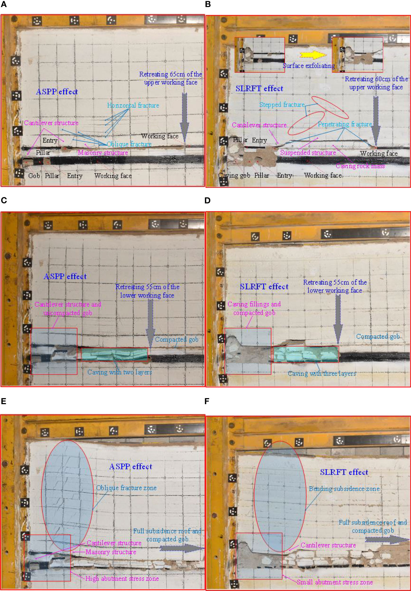
Figure 6 Structural morphology of bearing structure influenced by SLRFT and ASPP. (A) ASPP effect in stage I. (B) SLRFT effect in stage I. (C) ASPP effect in stage II. (D) SLRFT effect in stage II. (E) ASPP effect in stage III. (F) SLRFT effect in stage III.
Roofs above the gob that are affected by ASPP in stage I produce non-penetrating oblique and horizontal gaping fractures, whereas those that are affected by SLRFT produce stepped closed fractures and piercing fractures. When there are fracture differences, two-sided cantilever structures rise above the longwall entry and are influenced by ASPP, whereas one-sided cantilever structures rise above the longwall entry and are influenced by SLRFT. These structures include suspended structures and caving rock mass structures. When the roofs are dealt with SLRFT, the caving zone can completely cover the lower and upper gobs for the roofs above the lower gob and extends to the limestone above the upper coal seam. However, when the roofs are dealt with ASPP, caving zone only reaches the lower coal seam and cannot fill the bottom gob.
Stage II is characterized by the coupled retreating process in which sandy mudstone gradually caves to the lower gob floor. One ASPP has a greater effect on the duration of a caving step than two ASPPs do. The caving zone divides into two layers under the impact of one ASPP and into three layers under the influence of two ASPPs. The caving rock mass structure is simple to fracture and fill the gob due to the influence of SLRFT. However, the SLRFT has no effect on the masonry construction, which remains stable and suspended. The two-sided cantilever structure transforms into a single-sided cantilever structure with an oblique closed fracture and an uncompacted bottom gob. In contrast, the bottom gob of the one-side cantilever construction is still present and in the condition of compacting. The hanging structure sags and forces the caving rock mass structure to become more compressed.
In stage III, the gob was gradually compacted in certain areas, and the bearing structure remained steady above the longwall entry. Small caving height and partial filling cause the oblique fracture to form above the gob’s terminating side and spread to the higher roofs under the impact of ASPP. In contrast, the roofs above the terminating side of the gob gradually produce bending subsidence, and the prior cracks were compacted under the influence of significant caving height and the majority of filling brought on by SLRFT. The cantilever structure and the masonry structure, meanwhile, maintain stability and support the weight on the coal pillar and longwall entry under ASPP. Nevertheless, even in the presence of SLRFT, the cantilever structure maintains its stability and supports stresses on the longwall entry, the coal pillar, and the compacted gobs.
As can be seen in Figure 7A, SLRFT primarily works to reduce the rock’s abutment stress in the sandy mudstone beneath the lower coal pillar. In stage I, the top working face begins to retreat, and the abutment stress at point A gradually increases at first and then grows rapidly step by step later. SLRFT has a greater impact on it than ASPP does on its maximum value and growing velocity. The largest difference, roughly, is 2.57 kPa. In stage II, the abutment stress at point A, which is driven by ASPP, eventually stabilizes after a steady increase in fluctuation. Nevertheless, it drops quickly at first under the influence of SLRFT, then experiences enormous fluctuations, increases very slowly, decreases quickly afterward, and ultimately increases slowly and gradually. Approximately 10.88 kPa separates the final value. With a fluctuation between 12.5 kPa and 14.6 kPa in stage III, point A’s abutment stress under the impact of ASPP virtually stabilizes. However, it is affected by SLRFT, which causes it to climb gradually at first, decline quickly subsequently, and then stabilize gradually. SLRFT has a much smaller impact on the final value, 3.7 kPa, than ASPP, which has a much larger impact.
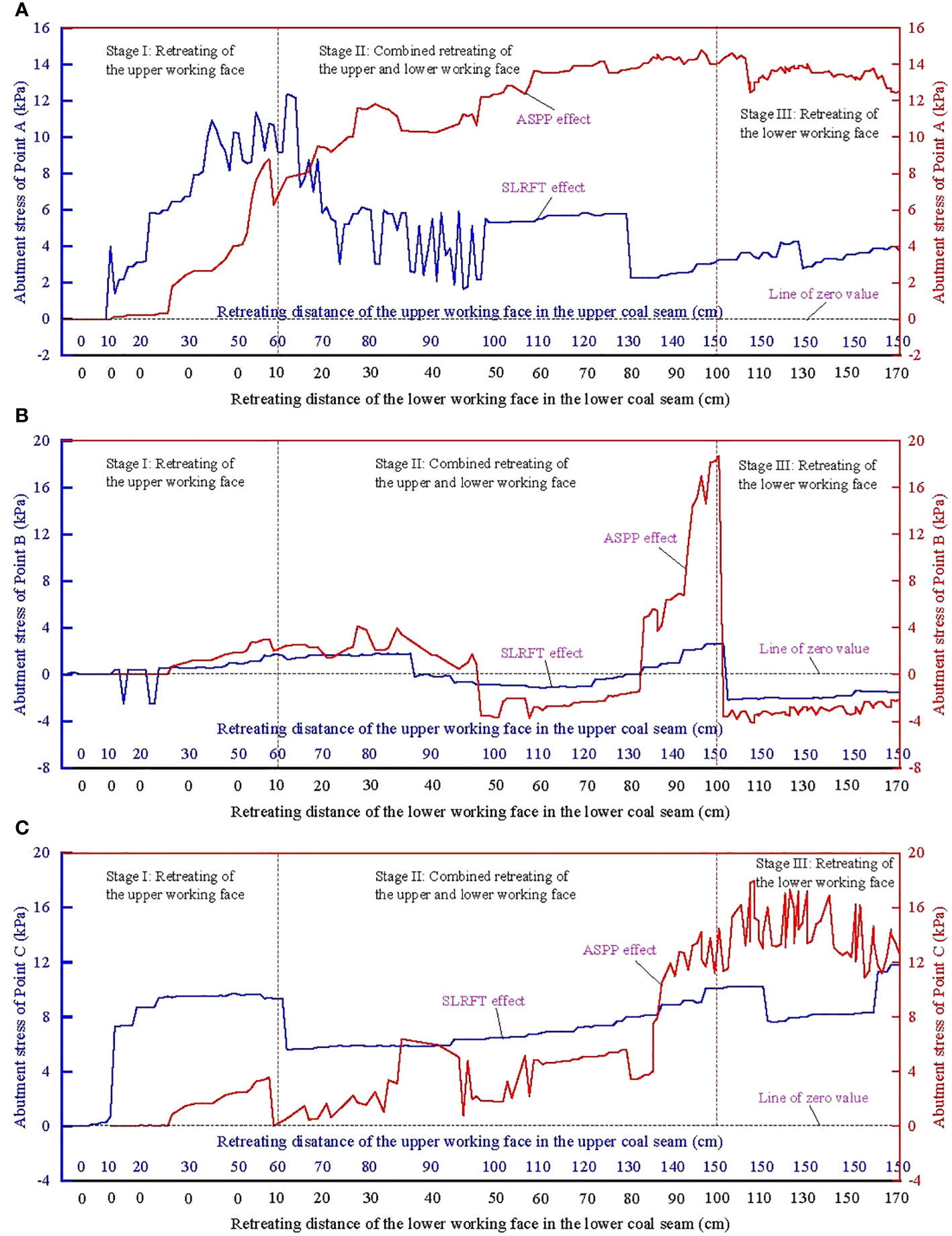
Figure 7 Abutment stress of rock influenced by SLRFT and ASPP. (A) Point A in the sandy mudstone below the lower coal pillar. (B) Point B in the sandy mudstone below the middle location of the lower working face. (C) Point C in the sandy mudstone above the lower coal pillar.
SLRFT is most effective, as demonstrated in Figure 7B, at reducing the rock’s abutment stress in the sandy mudstone beneath the middle portion of the lower working face. The abutment stress of point B grows gradually in stage I, then increases quickly, and eventually stabilizes. Its highest value under the impact of ASPP is 3.0 kPa, which is higher than 1.7 kPa under the influence of SLRFT. In stage II, the abutment stress at point B that is affected by the ASPP varies initially with a slight fluctuation, then reduces linearly step by step after that, then grows slowly step by step after that, and eventually increases extremely rapidly to the peak. It maintains stability at first under the impact of SLRFT, declines quickly after that, declines slowly after that, and eventually climbs quickly until it reaches its peak. The peak value affected by ASPP is 18.2 kPa, which is significantly higher than 2.6 kPa that was affected by SLRFT. In stage III, the abutment stress at point B rapidly drops to zero and then remains constant. The velocity that ASPP has caused is more than the velocity that SLRFT has altered.
The abutment stress of the rock in the sandy mudstone above the lower coal pillar is significantly influenced by SLRFT, as illustrated in Figure 7C. Abutment stress at point C under the influence of ASPP remains zero during stage I before increasing quickly and then decreasing quickly at the end. Whereas, the SLRFT-influenced variable maintains zero at first, increases gradually later, increases quickly after that, increases gradually after that, and stabilizes at last. Its greatest value affected by SLRFT is 9.7 kPa, a much higher amount than 3.6 kPa that was affected by ASPP. In stage II, the ASPP-influenced abutment stress at point C grows gently at first with variability, then quickly in the middle, and slowly toward the end. The SLRFT, however, causes it to decline quickly at first, remain stable afterward, and then grow gradually over time. Its maximum value that is affected by SLRFT is 10.1 kPa, a far lower amount than 14.2 kPa that is affected by ASPP. In stage III, the ASPP-influenced abutment stress of point C initially rises and then falls over time. In contrast, it is impacted by SLRFT and initially remains stable before decelerating quickly, increasing slowly, and eventually stabilizing. Its highest value that SLRFT can alter is 11.8 kPa, which is less than 18.0 kPa that ASPP may impact.
SLRFT is an effective way to weaken the abutment stress around the longwall entry under the close distance coal pillar during the combined retreating process of the upper and lower working face, although the partial overburden weight above the worked-out area still loads on the unworked-out area by the bearing structure (Jirankova et al., 2012). Compared with the traditional natural caving method (Wen et al., 2019), SLRFT weakens the abutment stress mainly through changing the stress transfer mechanism in a way of varying the structural morphology, fracture characteristics, and the movement behavior of the bearing structure above the worked-out area.
During the course of its use in the conventional natural caving method, the mining-induced abutment stress primarily passes through the upper coal pillar into the longwall entry. It primarily maintains stability and results from the stable abutment stress in the upper coal pillar before the upper working face retreats (Kang et al., 2017). The variational abutment stress in the higher coal pillar causes it to rise quickly as the upper working face retreats (Colwell et al., 1999). In the top coal pillar during the combined retreating of the upper and lower working faces, the variational abutment stress causes it to increase quickly once more (Liu et al., 2021).
According to Shen et al. (2019), SLRFT initially reduces the variational abutment stress in the coal pillar by altering the structural morphology of the bearing structure above the coal pillar. This is because the variational abutment stress in the coal pillar is primarily caused by the activation of the bearing structure above the coal pillar. In stage I, the bearing structure transitions from a two-sided T-shaped cantilever structure to a one-sided basin-shaped cantilever structure above the upper coal pillar, as well as from a masonry structure to a suspended structure and a caving rock mass next to the cantilever structure. With or without the help of SLRFT, it will produce rotational subsidence, new masonry structures, and one-side cantilever structures, but, in stages II and III, it only produces rotary subsidence.
SLRFT, which can lead to the various bearing structures discussed above, weakens the abutment stress surrounding the longwall entry under close distance coal pillar by altering the fracture characteristics of the bearing structure above the upper coal pillar. Stage I of the fracture involves non-penetrating horizontal and oblique gaping fractures that transition into stepped closed fractures and penetrating fractures in the roof above the worked-out area. In stage II, they will display behavior such as closure, extension, opening, and piercing. After then, without the help of SLRFT in stage III, a new oblique opening fracture develops and extends to the higher roofs. The effect of SLRFT in stage III compacted the earlier cracks into closure.
SLRFT alters the movement behavior of the bearing structure above the upper coal pillar, which can lead to the various fractures described above, weakening the abutment stress surrounding the longwall entry under close distance coal pillar. The main roof’s sinking changes from a moderate, linear trend to a rapid, stepped trend in stage II due to the immediate roof’s higher subsidence velocity under the effect of SLRFT than it would be without it. The primary cause is an improvement in stage II and stage III filling rates, compaction levels, and dilatancy of the caving rock mass due to shorter caving step lengths, more layered collapse, and greater caving heights of the immediate ceiling. As part of the overburden load is transferred into the worked-out area from the compacted worked-out area, the upper coal pillar’s loading may be compromised because of the worked-out area’s increased support area for the bearing structure.
Under the condition of the discussion, the bearing structure above the upper coal pillar is shown in Figure 8. AγH is the weight of the rock above the bearing structure. A is the abutment stress coefficient in the bearing structure. γ is the average volume weight. H is the buried depth of the rock strata. q is the support stress of the coal pillar. k is the support coefficient of the compacted worked-out area. kq is the support stress of the compacted worked-out area. x1 is the cantilever length of the bearing structure. x2 is the compacted length of the bearing structure. M is the bending moment of rock around the bearing structure. According to static equilibrium, the support stress of the coal pillar can be calculated using Equation (2). Its bearing capacity coefficient ζ can be calculated by Equation (3) for the determined geological and engineering conditions.
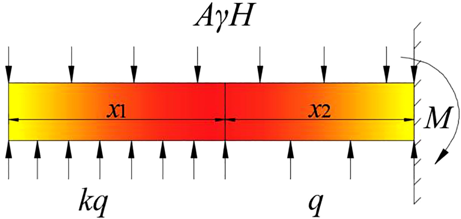
Figure 8 Mechanical condition of the bearing structure above the upper coal pillar.
To evaluate the loading impact of the bearing structure on the coal pillar, the bearing capacity coefficient can be used. As shown in Figure 9, it will vary depending on the cantilever length of the bearing structure and the support coefficient of the compacted worked-out region. Shorter cantilever length and higher support coefficient may be able to reduce the abutment stress in the coal pillar. This is because the bearing capacity coefficient will rise as the cantilever length of the bearing structure increases and will fall as the support coefficient of the compacted worked-out area increases. This may help to explain how SLRFT is able to reduce the abutment stress surrounding the longwall entry when the coal pillar is situated close by.
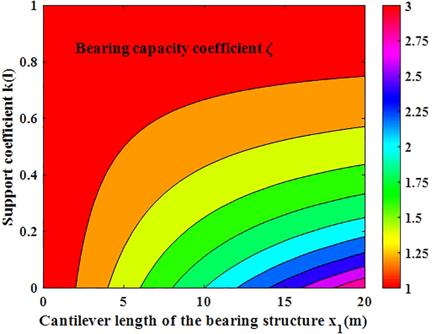
Figure 9 Evolution of the bearing capacity coefficient.
When there are deep rock strata beneath the coal pillar, hard roofs above the coal pillar, and wide caving rock mass in the worked-out area in nearby coal seams, SLRFT can be employed to lessen the abutment stress surrounding the longwall entry. The implications of the vertical separation in the stress propagation path between the close-proximity coal seams and the discontinuous interface on the SLRFT, however, need to be further investigated in the future.
When the longwall entry encounters the evolution of the abutment stress brought on by numerous mining activities, it is challenging to prevent the close-proximity coal pillar from experiencing significant deformation. SLRFT was proposed to lessen the abutment stress surrounding longwall entry and lessen the significant distortion of this type of entry.
SLRFT, a technique for remodeling roof-bearing structures under mining disturbance, consists of three interactive components: the ASPP, the ASPI, and the MALU. By dividing the lower thick rock stratum into numerous straticulate rock structures along ASPP under MALU, ASPP significantly contributes to the acceleration of the lower thick rock strata’s movement. By dividing the upper thick hard roof into two portions along ASPI under MALU, ASPI plays a crucial function in identifying the site of the fracture of the upper thick hard roof.
The mechanism for the lowering of abutment stress was shown using two physical simulation models with plane–stress circumstances. SLRFT lengthens the stress transmission path by altering the bearing structure’s movement patterns, fracture characteristics, and structural morphology above the coal pillar. First, the fracture in the ceiling above the worked-out area shifts from a non-penetrating horizontal and oblique gaping fracture to stepped closed fractures and piercing fractures. Second, the main roof’s subsidence changed from having a steady, linear pattern to one that was swift and stepped. The bearing structure finally switches from a two-sided cantilever structure with a T type to a single-sided cantilever structure with a basin type.
SLRFT results in a shorter step length, a more stratified collapse, and a higher caving height of the immediate roof, which enhances the dilatancy of the caving rock mass, the filling rate, and the degree of compaction of the worked-out region. Because the compacted worked-out region has a bigger support area, more of the overburden load is transferred there, weakening the abutment stress around the longwall entry from 12.5 kPa to 3.7 kPa. The degree of stress reduction increases when the cantilever length of the bearing structure is decreased and the support coefficient of the compacted worked-out area is increased.
When there are deep rock strata beneath the coal pillar, hard roofs above the coal pillar, or wide caving rock masses in the worked-out area in close-by coal seams, SLRFT is an effective approach to reduce the abutment stress around the longwall entry. The implications of the vertical separation in the stress propagation path between the close-proximity coal seams and the discontinuous interface on the SLRFT, however, need to be further investigated in the future. A feasibility, efficacy, and design analysis of SLRFT in various engineering geological settings can be done using the established experimental model.
The original contributions presented in the study are included in the article/supplementary material. Further inquiries can be directed to the corresponding author.
JL: Conceptualization, Investigation, Writing – review & editing. WS: Funding acquisition, Methodology, Writing – original draft. JB: Conceptualization, Supervision, Writing – review & editing. CS: Data curation, Validation, Writing – review & editing. XL: Data curation, Visualization, Writing – review & editing.
The authors declare financial support was received for the research, authorship, and/or publication of this article. This work is supported by the National Natural Science Foundation of China (contract 52274077), the Fundamental Research Funds for the Universities of Henan Province (NSFRF220440), the Funds for Distinguished Young Scholars of Henan Polytechnic University (J2023-3), and the Funds for Establishment Project of Double First-Class Disciplines of Safety and Energy Engineering Department (AQ20230736).
The authors declare that the research was conducted in the absence of any commercial or financial relationships that could be construed as a potential conflict of interest.
All claims expressed in this article are solely those of the authors and do not necessarily represent those of their affiliated organizations, or those of the publisher, the editors and the reviewers. Any product that may be evaluated in this article, or claim that may be made by its manufacturer, is not guaranteed or endorsed by the publisher.
Bai J. B., Shen W. L., Guo G. L., Wang X. Y., Yu Y. (2015). Roof deformation, failure characteristics, and preventive techniques of gob-side entry driving heading adjacent to the advancing working face. Rock Mechanics Rock Eng. 48 (6), 2447–2458. doi: 10.1007/s00603-015-0713-2
Colwell M., Frith R., Mark C. (1999). Analysis of longwall tailgate serviceability (ALTS): a chain pillar design methodology for Australian conditions. Coal Pillar Mech. Des., 33–48.
Hou C. J., Ma N. J. (1989). Stress in in-seam roadway sides and limit equilibrium zone. J. China Coal Soc. 4, 21–29. doi: 10.13225/j.cnki.jccs.1989.04.003
Huang B. X., Liu J. W., Zhang Q. (2018). The reasonable breaking location of overhanging hard roof for directional hydraulic fracturing to control strong strata behaviors of gob-side entry. Int. J. Rock Mechanics Min. Sci. 103, 1–11. doi: 10.1016/j.ijrmms.2018.01.013
Jirankova E., Petros V., Sancer J. (2012). The assessment of stress in an exploited rock mass based on the disturbance of the rigid overlying strata. Int. J. Rock Mechanics Min. Sci. 50, 77–82. doi: 10.1016/j.ijrmms.2012.01.004
Kang J. Z., Shen W. L., Bai J. B., Yan S., Wang X. Y., Li W. F., et al. (2017). Influence of abnormal stress under a residual bearing coal pillar on the stability of a mine entry. Int. J. Min. Sci. Technol. 27 (6), 945–954. doi: 10.1016/j.ijmst.2017.06.012
Kang H. P., Wu L., Gao F. Q., Lv H. W., Li J. Z. (2019). Field study on the load transfer mechanics associated with longwall coal retreat mining. Int. J. Rock Mechanics Min. Sci. 124, 1–10. doi: 10.1016/j.ijrmms.2019.104141
Li W. F., Bai J. B., Peng S., Wang X. Y., Xu Y. (2015). Numerical modeling for yield pillar design: A case study. Rock Mechanics Rock Eng. 48 (1), 305–318. doi: 10.1007/s00603-013-0539-8
Li H. T., Li X. L., Fu J. H., Zhu N. Q., Chen Y. W., Ding S., et al. (2023). Experimental study on compressive behavior and failure characteristics of imitation steel fiber concrete under uniaxial load imitation steel fiber concrete under uniaxial load. Construction Building Materials 399 (8), 132599. doi: 10.1016/j.conbuildmat.2023.132599
Liu S. M., Li X. L. (2023). Experimental study on the effect of cold soaking with liquid nitrogen on the coal chemical and microstructural characteristics. Environ. Sci. pollut. Res. 30 (3), 36080–36097. doi: 10.1007/s11356-022-24821-9
Liu H. M., Li X. L., Yu Z. Y. (2023a). Influence of hole diameter on mechanical properties and stability of granite rock surrounding tunnels. Phys. Fluids 35 (6), 064121. doi: 10.1063/5.0154872
Liu X. D., Shen W. L., Bai J. B., Wang R., Kang J. Z., Wang X. Y. (2021). Mining-induced redistribution of the abnormal stress under the close bearing coal pillar for entry design. Adv. Civil Eng. 2021, 1–13. doi: 10.1155/2021/5595372
Liu S. M., Sun H. T., Zhang D. M. (2023b). Experimental study of effect of liquid nitrogen cold soaking on coal pore structure and fractal characteristics. Energy 275 (7), 127470. doi: 10.1016/j.energy.2023.127470
Liu H. Y., Zhang B. Y., Li X. L., Liu C. W., Wang C., Wang F., et al. (2022). Research on roof damage mechanism and control technology of gob-side entry retaining under close distance gob. Eng. Failure Anal. 138, 1–16. doi: 10.1016/j.engfailanal.2022.106331
Meng Z. X., Dong Y., Zhang X. G., Jiao F. S., Fan Y. Q., Thammavongsa C. (2023). Short-wall paste continuous mining and continuous backfilling for controlling industrial square surface subsidence. Front. Earth Sci. 10. doi: 10.3389/feart.2022.1009617
Ning J. G., Wang J., Tan Y. L., Xu Q. (2020). Mechanical mechanism of overlying strata breaking and development of fractured zone during close-distance coal seam group mining. Int. J. Min. Sci. Technol. 30 (2), 207–215. doi: 10.1016/j.ijmst.2019.03.001
Shen W. L., Bai J. B., Wang X. Y., Yu Y. (2016). Response and control technology for entry loaded by mining abutment stress of a thick hard roof. Int. J. Rock Mechanics Min. Sci. 90, 26–34. doi: 10.1016/j.ijrmms.2016.10.001
Shen W. L., Shi G. C., Wang Y. G., Bai J. B. A., Zhang R. F., Wang X. Y. (2021). Tomography of the dynamic stress coefficient for stress wave prediction in sedimentary rock layer under the mining additional stress. Int. J. Min. Sci. Technol. 31 (4), 653–663. doi: 10.1016/j.ijmst.2021.04.003
Shen W. L., Shi G. C., Wang M., Rong T. L., Wang Y. G., Zhang R. F., et al. (2020). Method of entry layout under synergistic effects of abutment stress and dynamic stress. Shock Vibration 2020, 1–16. doi: 10.1155/2020/6655293
Shen W. L., Wang M., Cao Z. Z., Su F. Q., Nan H., Li X. L. (2019). Mining-induced failure criteria of interactional hard roof structures: A case study. Energies 12 (15), 1–17. doi: 10.3390/en12153016
Sun Y. T., Bi R. Y., Sun J. B., Zhang J. F., Taherdangkoo R., Huang J. D., et al. (2022). Stability of roadway along hard roof goaf by stress relief technique in deep mines: a theoretical, numerical and field study. Geomechanics Geophysics Geo-Energy Geo-Resources 8 (2), 1–16. doi: 10.1007/s40948-022-00356-8
Tu S. H. (2010). Experimental method and measurement technique of rock control (Xuzhou, China: China University of Mining and Technology Press).
Wang X. Y., Bai J. B., Wang R. F., Sheng W. L. (2015). Bearing characteristics of coal pillars based on modified limit equilibrium theory. Int. J. Min. Sci. Technol. 25 (6), 943–947. doi: 10.1016/j.ijmst.2015.09.010
Wang Q., He M. C., Li S. C., Jiang Z. H., Wang Y., Qin Q., et al. (2021). Comparative study of model tests on automatically formed roadway and gob-side entry driving in deep coal mines. Int. J. Min. Sci. Technol. 31 (4), 591–601. doi: 10.1016/j.ijmst.2021.04.004
Wang Y. J., He M. C., Yang J., Wang Q., Liu J. N., Tian X. C., et al. (2020). Case study on pressure-relief mining technology without advance tunneling and coal pillars in longwall mining. Tunnelling Underground Space Technol. 97, 1–13. doi: 10.1016/j.tust.2019.103236
Wen J. H., Cheng W. M., Chen L. J., Shi S. S., Wen Z. J. (2019). A study of the dynamic movement rule of overlying strata combinations using a short-wall continuous mining and full-caving method. Energy Sci. Eng. 7 (6), 2984–3004. doi: 10.1002/ese3.474
Wilson A. H., Ashwin D. P. (1972). Research into the determination of pillar size. Min. Eng. 131 (141), 409–417.
Xia K. Z., Chen C. X., Wang T. L., Zheng Y., Wang Y. (2022). Estimating the geological strength index and disturbance factor in the Hoek-Brown criterion using the acoustic wave velocity in the rock mass. Eng. Geol. 306, 106745. doi: 10.1016/j.enggeo.2022.106745
Ye D. Y., Liu G. N., Wang F. T., Gao F., Yang T. T., Zhu J. Y. (2023). Fractal hydrological-thermal-mechanical analysis of unconventional reservoir: A fracture-matrix structure model for gas extraction. Int. J. Heat Mass Transfer 202, 123670. doi: 10.1016/j.ijheatmasstransfer.2022.123670
Yuan F., Tang J. X., Kong L. R., Li C. (2023). Layout timing of mining roadways considering goaf and roof stability. Front. Earth Sci. 10. doi: 10.3389/feart.2022.1092585
Zhang Z. Z., Deng M., Bai J. B., Yu X. Y., Wu Q. H., Jiang L. S. (2020). Strain energy evolution and conversion under triaxial unloading confining pressure tests due to gob-side entry retained. Int. J. Rock Mechanics Min. Sci. 126, 1–10. doi: 10.1016/j.ijrmms.2019.104184
Zhang J. X., Li B. Y., Zhou N., Zhang Q. (2016). Application of solid backfilling to reduce hard-roof caving and longwall coal face burst potential. Int. J. Rock Mechanics Min. Sci. 88, 197–205. doi: 10.1016/j.ijrmms.2016.07.025
Zhang L., Shen W., Li X., Wang Y., Qin Q., Lu X., et al. (2022b). Abutment pressure distribution law and support analysis of super large mining height face. Int. J. Environ. Res. Public Health 20 (1), 1–16. doi: 10.3390/ijerph20010227
Zhang F. T., Wang X. Y., Bai J. B., Wu W. D., Wu B. W., Wang G. H. (2022a). Fixed-length roof cutting with vertical hydraulic fracture based on the stress shadow effect: A case study. Int. J. Min. Sci. Technol. 32 (2), 295–308. doi: 10.1016/j.ijmst.2021.09.007
Zhang Z. B., Wang E. Y., Li N., Zhang H. T., Bai Z. M., Zhang Y. H. (2023a). Research on macroscopic mechanical properties and microscopic evolution characteristic of sandstone in thermal environment. Construction Building Materials 366, 130152. doi: 10.1016/j.conbuildmat.2022.130152
Zhang Z. B., Wang E. Y., Zhang H. T., Bai Z. M., Zhang Y. H., Chen X. (2023b). Research on nonlinear variation of elastic wave velocity dispersion characteristic in limestone dynamic fracture process. Fractals 31 (1), 2350008. doi: 10.1142/S0218348X23500081
Zhang J. C., Li X. L., Qin Q. Z. (2023c). Study on overlying strata movement patterns and mechanisms in super-large mining height stopes. Bull. Eng. Geology Environ. 82 (3), 142. doi: 10.1007/s10064-023-03185-5
Keywords: separated layer rock failure technology, abutment stress reduction, longwall entry under coal pillar, combined mining of close distance coal seams, bearing structure above the coal pillar
Citation: Liu J, Shen W, Bai J, Shan C and Liu X (2023) Experiment on separated layer rock failure technology for stress reduction of entry under coal pillar in mining conditions. Front. Ecol. Evol. 11:1265883. doi: 10.3389/fevo.2023.1265883
Received: 24 July 2023; Accepted: 17 August 2023;
Published: 07 September 2023.
Edited by:
Xuelong Li, Shandong University of Science and Technology, ChinaReviewed by:
Wenda Wu, Taiyuan University of Technology, ChinaCopyright © 2023 Liu, Shen, Bai, Shan and Liu. This is an open-access article distributed under the terms of the Creative Commons Attribution License (CC BY). The use, distribution or reproduction in other forums is permitted, provided the original author(s) and the copyright owner(s) are credited and that the original publication in this journal is cited, in accordance with accepted academic practice. No use, distribution or reproduction is permitted which does not comply with these terms.
*Correspondence: Wenlong Shen, c2hlbndlbmxvbmcuODg4QDE2My5jb20=
Disclaimer: All claims expressed in this article are solely those of the authors and do not necessarily represent those of their affiliated organizations, or those of the publisher, the editors and the reviewers. Any product that may be evaluated in this article or claim that may be made by its manufacturer is not guaranteed or endorsed by the publisher.
Research integrity at Frontiers
Learn more about the work of our research integrity team to safeguard the quality of each article we publish.