- 1School of Civil Engineering and Architecture, Xi’an University of Technology, Xi’an, China
- 2International Joint Research Laboratory of Henan Province for Underground Space Development and Disaster Prevention, Henan Polytechnic University, Jiaozuo, Henan, China
- 3Shaanxi Geological Survey Center of Hydrogeology, Engineering Geology and Environmental Geology, Shaanxi Institute of Geological Survey, Xi’an, China
- 4Zibo Aojing Garden Co., Ltd, Zibo, Shandong, China
Liquid nitrogen fracturing and hot dry rock geothermal development are both emerging technologies in the field of energy. However, during the extraction of geothermal energy, it can cause the evolution of geological fractures, leading to the diffusion of groundwater and pollutants, thereby causing environmental pollution issues. Currently, geothermal energy has become a focal point in the global development of renewable energy. However, traditional hydraulic fracturing methods used in harnessing geothermal resources suffer from limitations such as limited fracture creation, uncertain initiation points, and environmental pollution. In contrast, liquid nitrogen has emerged as a promising reservoir stimulation technique, exhibiting significant effects on rock fracturing. In this study, we conducted three-point bending tests on granite samples subjected to liquid nitrogen treatment at temperatures of 300°C, with varying numbers of cooling cycles. Changes in fundamental mechanical parameters were analyzed. Additionally, through acoustic emission monitoring, we studied the variations in characteristic parameters of acoustic emissions under different cooling cycle conditions. Furthermore, based on the theory of energy evolution, we analyzed the energy evolution process during sample failure under different cooling cycle conditions. Using a compact scanning electron microscope, we observed changes in the microstructure of granite and analyzed the influence of cooling treatment on its surface characteristics and failure modes, thereby revealing the thermal damage process of granite. Moreover, by employing a non-metallic ultrasonic testing analyzer, we scanned the fracture surface morphology of granite and investigated the variations in fracture surface morphology features and surface roughness parameters caused by cooling treatment. The results indicate that liquid nitrogen cooling treatment can more effectively reduce the mechanical properties of rocks, and this effect is further enhanced at high temperatures. Under the condition of 300°C, after undergoing different cycles of liquid nitrogen cooling, granite will exhibit a more diverse macroscopic and microscopic structural failure characteristics, consistent with the expected formation of fluid flow channels in high-temperature rock formations.
1 Introduction
Liquid nitrogen fracturing technology is an emerging technique for extracting geothermal hot dry rock resources, which can significantly improve the fracture structure of high-temperature formations and enhance the efficiency of geothermal energy extraction. However, Liquid nitrogen fracturing technology may have some significant impacts on the ecological environment. Firstly, the preparation of liquid nitrogen and the construction of geothermal reservoirs require a large amount of water resources, which could potentially damage water supply systems and ecosystems in certain areas. Secondly, the used wastewater and waste materials may contain certain chemicals or heavy metals, posing a certain threat to water sources and ecosystems. Thirdly, geothermal energy extraction through Liquid nitrogen fracturing technology can cause surface changes, which may have a significant impact on local topography, vegetation, animal habitats, and ecosystem stability. Therefore, it is important to be mindful of environmental protection and minimize potential impacts on local ecosystems during the process of energy extraction. Understanding the specific degradation effects of Liquid nitrogen fracturing technology on hot dry rock reservoirs is crucial prior to engaging in geothermal energy extraction and environmental protection.
Energy is a fundamental driver of sustainable development and societal progress, intricately intertwined with national security and the overall well-being of a society. Throughout history, energy revolutions have propelled industrial advancements and shaped the global landscape (Wang et al., 2020). Amidst the escalating challenges of environmental pollution, climate change, and the depletion of fossil fuel reserves, there is a growing sense of urgency to prioritize the development and utilization of clean, renewable energy sources (Batchelor, 1985; Li et al., 2019; Chen et al., 2022; Kang et al., 2023). Geothermal energy, a noteworthy non-fossil fuel source, offers diverse applications along with its inherent cleanliness and recyclability. Its vast reserves position geothermal energy as a vital alternative for future societal development. Geothermal resources encompass hydrothermal and enhanced geothermal systems (EGS), classified based on extraction conditions and origins (Climo et al., 2016). Hydrothermal resources currently dominate global geothermal utilization, accounting for approximately 10% of identified reserves. Conversely, EGS represents an emerging strategic energy source, with the potential to drive global energy growth. Acting as a reservoir for geothermal energy within the Earth’s interior, EGS epitomizes a widely distributed, abundant, and environmentally friendly geothermal resource. Typically comprised of granite, granodiorite, and biotite granite, EGS reservoir rocks exemplify common compositions (Lu and Wang, 2015). EGS geothermal resources primarily refer to economically viable, shallow-depth, high-temperature rock bodies with low permeability. The energy contained within EGS reservoirs at depths of 3–10 kilometers is much greater than that of global fossil fuels (Xu et al., 2012). The effective development of EGS resources holds significant implications for global energy restructuring, combating climate change, and bolstering air quality control (Ma et al., 2020). However, the challenges lie in the low porosity, low permeability, compactness, and substantial burial depth of high-temperature EGS resources, making extraction difficult. To establish effective hydraulic connections, enhance heat transfer efficiency, and surmount these obstacles, the U.S proposed the concept of EGS. EGS entails the construction of geothermal reservoirs using artificial methods and comprises two subsystems. The first subsystem centers around developing and constructing underground heat reservoirs, achieved by enhancing reservoir permeability through various stimulation techniques. This allows for the creation of artificial reservoirs within low-porosity, low-permeability, high-temperature rock formations. The injection of cold water into the reservoirs via injection wells facilitates heat extraction, subsequently enabling the extraction of hot water or steam to the surface through production wells. The second subsystem involves utilizing the extracted geothermal water for on-surface power generation and heating systems. High-temperature water is a crucial resource for electricity generation, with the cooled water subsequently being recycled back into the underground reservoir (Wang and Li, 2008). This technology maximizes the utilization of deep geothermal resources distributed worldwide, offering substantial competitive advantages in terms of environmental impact, climate suitability, and economic viability.
Creating effective fluid pathways within EGS reservoirs poses a significant challenge. Reservoir stimulation techniques, such as hydraulic fracturing, thermal stimulation, and chemical stimulation, are commonly employed (Guo et al., 2020). Among these techniques, hydraulic fracturing currently stands as the most widely utilized and efficient method for reservoir modification (Xu et al., 2015; Xue et al., 2023a). Through hydraulic fracturing, fractures are generated, providing essential flow channels for fluid heat transfer. However, practical engineering often yields a single large fracture, which fails to meet the desired requirements of sufficient heat exchange area in EGS projects. Additionally, traditional hydraulic fracturing techniques entail uncertainties in fracture initiation, environmental pollution, and the risk of induced seismic events (Chen et al., 2019). At the same time, the chemical additives used in hydraulic fracturing techniques and chemical stimulation methods may contaminate groundwater and cause environmental pollution. In light of the drawbacks associated with traditional reservoir stimulation technologies, it is imperative to propose a new reservoir fracturing technique. Liquid nitrogen, as an innovative waterless fracturing technique, holds promise for EGS development (Huang and Meng, 2018). When dry rock contacts liquid nitrogen as the fracturing fluid, considerable thermal stress arises due to the substantial temperature difference between the two (Zhang S. et al., 2018). Consequently, numerous thermally induced cracks emerge in the reservoir, facilitating the establishment of a fracture network in EGS reservoirs. Liquid nitrogen undergoes a phase transition to gas under high temperatures, which further increases the extent of fracturing in reservoir rocks. Nitrogen gas itself is colorless and odorless, belonging to inert gases, and does not cause pollution to the environment. Against this engineering backdrop, exploring the cooling treatment of high-temperature rocks using liquid nitrogen serves as a vital foundation for the application of waterless fracturing in oil and gas extraction, geothermal resource development, and deep rock mechanics studies (Wang et al., 2023; Xue et al., 2023b). Furthermore, this study’s sequence of experiments and numerical calculations elucidates the potential application of nitrogen-induced fracturing in EGS development, offering guidance and technical parameters for nitrogen-induced fracturing in geothermal development.
The liquid nitrogen fracturing technology has not been applied in actual engineering of hot dry rock reservoirs yet. Scholars both domestically and internationally have conducted extensive research on the feasibility and mechanism of this technology. Cai et al. (2015) summarized the mechanism and key technologies of rock fracturing using liquid nitrogen. They pointed out that liquid nitrogen fracturing has advantages such as high efficiency and effective extraction of reservoir heat energy. Cai et al. (2016b) and Memon et al. (2020) conducted a series of mechanical experiments to research the mechanical characteristics and surface changes of rock under liquid nitrogen cooling. They analyzed the mechanism and influencing factors of rock fracturing induced by liquid nitrogen. Furthermore, the potential application of liquid nitrogen fracturing technology in petroleum engineering and shale gas development was explored, alongside the proposition of utilizing liquid nitrogen jet fracturing as a technique to enhance reservoir production. Through numerical simulation and experimental verification, the findings demonstrated that liquid nitrogen jet fracturing has obvious advantages compared to conventional liquid nitrogen fracturing techniques. Li et al. (2016) proposed a new liquid nitrogen gasification fracturing technology for low-permeability oil and gas reservoirs. Zhang et al. (2015) conducted laser microcosmic observation experiments and found that the cooling of coal by liquid nitrogen can cause thermal stress and stress concentration, resulting in the generation and expansion of microcracks within the original samples. Grundmann et al. (1998) conducted experiments on shale fracturing with liquid nitrogen, and their findings displayed that compared to traditional extraction methods, liquid nitrogen fracturing can increase gas production rate by up to 8%. Coetzee et al. (2014) discovered that fracturing with liquid nitrogen is capable of encouraging the development and expansion of rock fractures. According to McDaniel et al. (1997), when liquid nitrogen is introduced into coalbed gas reservoirs, it produces thermal shock, which causes physical changes in the fracture surfaces, impeding the closure of hydraulic fractures and thermally induced fractures.
Stephen (2013), in an article introducing waterless fracturing, demonstrated through experiments the influence of thermal impact on rocks during liquid nitrogen fracturing. Cha et al. (2014) found that when liquid nitrogen gets into interaction with rocks, a temperature gradient is formed on the surface, causing internal micro-damage to the rocks. When liquid nitrogen gets into interaction with the adjacent medium near the borehole, a cold impact is generated, causing severe contraction of the rock framework, resulting in fracture and the generation of numerous microcracks. Finnie et al. (1979) studied the fracture propagation pattern of rocks after liquid nitrogen treatment by injecting liquid nitrogen into the center of cubic rock samples and provided an analytical solution for the elastic body in a semi-infinite space under cooling conditions.
The process of developing enhanced geothermal reservoirs with the aid of liquid nitrogen fracturing technology differs from other reservoir modification methods. When exposed to high-temperature rock, liquid nitrogen generates significant thermal stress on the reservoir surface, resulting in the formation of numerous thermal-induced cracks and intricate fracture networks. These fractures facilitate the expansion of heat transfer surfaces, aligning with our development objectives.
Several studies have demonstrated that different cooling techniques exert notable influences on the mechanical characteristics of granite and shale. For instance, natural cooling and water cooling alter the mechanical performance of granite, with water cooling treatments being detrimental to its mechanical properties. Furthermore, liquid nitrogen cooling induces considerable damage to the mechanical characteristics of both granite and shale, leading to a reduction in peak stress, elastic modulus, longitudinal wave velocity, and other key mechanical characteristics (Wang et al., 2013; Cai et al., 2016a; Huang et al., 2016; Liang et al., 2018; Wu et al., 2018; Liu et al., 2023).
In addition, the thermal stresses caused by rapid temperature changes significantly affect rock integrity, resulting in diverse variations in the mechanical parameters of different rock types during thermal cycling processes. Coarse-grained heterogeneous rocks tend to exhibit crack propagation, whereas fine-grained homogeneous rocks tend to experience crack closure (Hall, 1999; Kim et al., 2014; Zhang F. et al., 2018).
Based on the aforementioned investigations, the impacts of various thermal cycling frequencies on rock mechanics, acoustic emission characteristics, and energy evolution patterns can be studied through three-point bending tests and acoustic emission monitoring systems. These research endeavors contribute to a comprehensive comprehension of how rock’s physical and mechanical qualities change during liquid nitrogen-assisted enhanced geothermal reservoir development, providing scientific foundations for engineering practices.
2 Experimental materials and procedures
2.1 Experimental materials
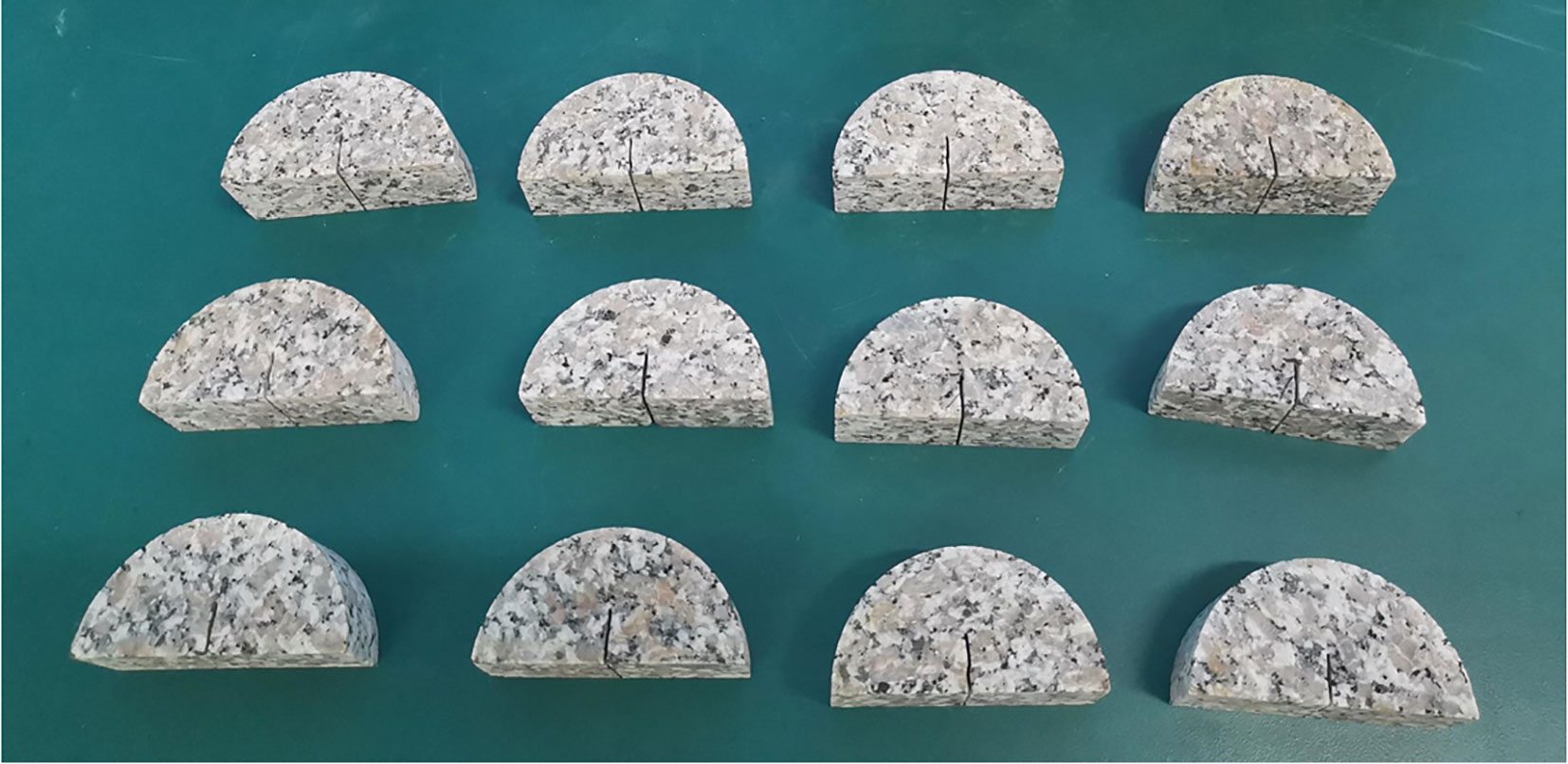
Based on statistics from internationally representative Enhanced Geothermal Systems (EGS) projects, the predominant lithology of EGS reservoir rocks both domestically and internationally is usually granite (igneous rock) or metamorphic rock. Therefore, in this study, granite is chosen as the focus of research. The granite samples used in the experiment exhibit lithological consistency with the rocks found in underground storage reservoirs of liquefied natural gas (LNG), thus making them suitable as load-bearing rock layers for large-scale LNG storage facilities. Following the guidelines outlined by the International Society for Rock Mechanics (ISRM) (Hardy, 1981), the specimens are prepared as semi-circular disk-shaped samples with a diameter (D) of 76 mm, radius (R) of 38 mm, thickness (B) of 30 mm, and an initial crack length (a) of 14 mm. To ensure uniformity, meticulous care is taken to polish the surfaces of the specimens, resulting in a smooth and even finish. Granite as shown in Figure 1.
2.2 Experimental equipment
As shown in Figure 2, a variety of instruments and equipment were used in the experiment, including a heating chamber, liquid nitrogen tank, vernier caliper, electronic scale, rock mechanics testing machine (capable of applying loads perpendicular to the sample surface), non-metallic ultrasonic testing and analysis instrument, and a three-point bending fixture. These devices were utilized for different experimental objectives to ensure the accuracy of the experiment.
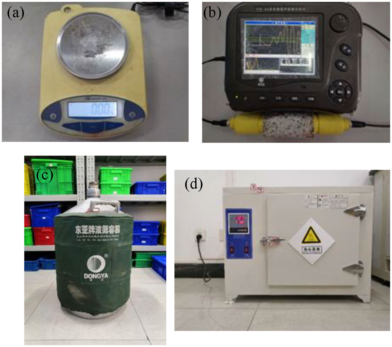
Figure 2 Experimental equipment: (A) Electronic scale; (B) Non-metallic ultrasonic monitoring analyzer; (C) Liquid nitrogen tank; (D) Heating box.
2.3 The experimental scheme
To conduct the experiment, the selected rock samples were categorized into multiple groups and assigned numerical labels based on the number of cycles: 3, 5, 7, 9, 15, and 20. Initially, each sample was subjected to a controlled heating process inside a calibrated heating chamber, gradually reaching a target temperature of 300°C. After reaching the target temperature, the specimen is kept at a constant temperature in the heating chamber for 3 hours. This ensured uniform thermal conditions throughout the samples, guaranteeing consistent heating across both their internal and external regions. Following the completion of the thermal treatment, the samples were swiftly extracted from the heating chamber and rapidly immersed in a liquid nitrogen tank for an hour-long cooling period. Careful attention was paid to prevent overflowing of the liquid nitrogen, considering the vigorous boiling that ensues when immersing high-temperature rocks. Once the cooling process was finalized, the samples were placed back into the same controlled environment for subsequent three-point bending experiments. The experiment utilizes the CSS-44100 Testing Machine. To ensure the accuracy and reliability of the experiment, we set up multiple parallel samples for each cycle.
The specimen was securely affixed to the three-point bending fixture, ensuring compatibility between its size, shape, and fracture behavior with the adjusted lower support rollers and upper loading head. During the three-point bending experiment, displacement control is employed, with a loading rate set at 0.1mm/min. Adjacent to this setup, a high-speed camera was strategically positioned to meticulously record the temporal evolution of the specimen’s response to the loading conditions, diligently transmitting the acquired data to a dedicated computer system. Consequently, a comprehensive load-displacement curve was meticulously constructed, while purpose-built image analysis software enabled an intricate examination of the surface displacement and strain fields exhibited by the specimen. By meticulously analyzing the displacement of the loading head, the applied load, and the unique deformation characteristics observed near the crack tip area, we were able to accurately calculate the fracture toughness and crack propagation velocity inherent to the rock material.
3 Mechanical behavior of granite
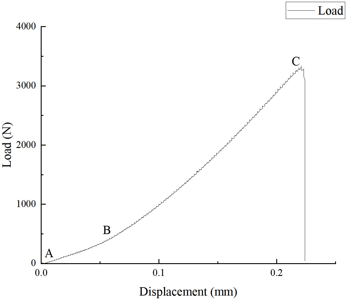
The load-displacement curve serves as an invaluable tool to elucidate the intricate deformation and failure mechanisms intrinsic to the bending process of granite specimens. Figure 3 shows a classic load-displacement curve of samples. Typically, this curve manifests itself through three distinctive phases: the elastic stage, the elastic-plastic stage, and the failure stage. By referring to the initial dataset, which has not undergone any treatments, we can gain insightful observations.
During the elastic stage (AB), granite demonstrates a linear relationship between its deformation and the applied load, meticulously abiding by Hooke’s Law. Within this stage, the deformation encountered by the granite sample proves to be entirely recoverable, restoring the specimen to its original configuration upon unloading.
As the applied load progressively intensifies, the elastic-plastic stage (BC) commences, whereby the deformation no longer mirrors the applied load in a linear fashion, prompting the characteristic curve to deviate from its linear trajectory. Intriguingly, this stage showcases a combination of both elastic and plastic deformation within the granite sample, thereby instigating the creation of intricate networks of microcracks and voids. Importantly, it is crucial to note that the plastic deformation encountered by the granite specimen proves to be inherently irreversible, inescapably leaving a discernible degree of residual deformation upon unloading.
Ultimately, as the load surpasses a critical threshold, the failure stage (post C) ensues, heralding a profound deviation from the previously established linear relationship between load and deformation. Indeed, within this stage, the granite specimen experiences a rapid progression in microcrack propagation and void connectivity, invariably resulting in a precipitous decline in both strength and stiffness.
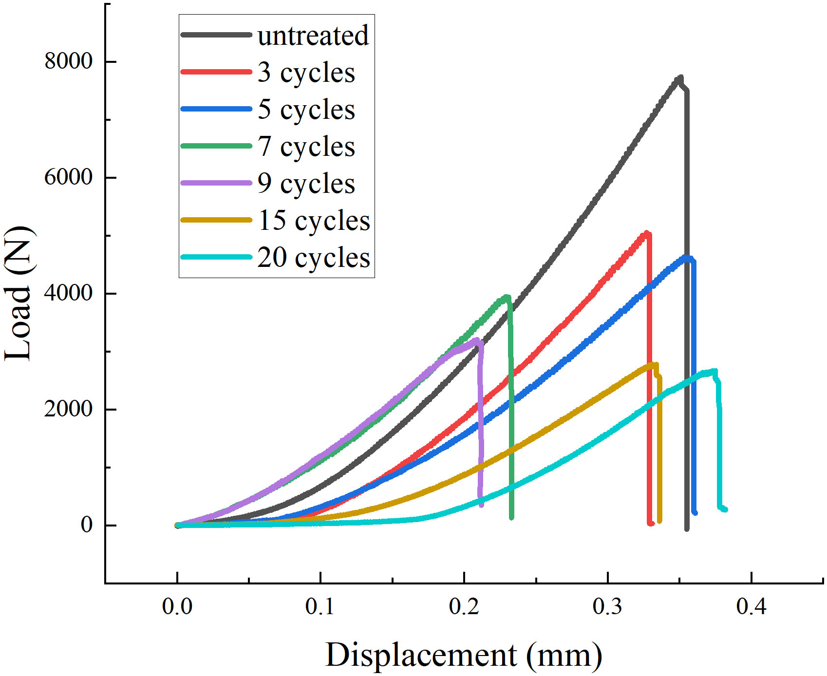
To investigate the impact of the number of cycles at a constant temperature on the load-displacement curve of granite, we conducted a comparative analysis of the curves presented in Figure 4. Herein, we derive the following observations. In the elastic stage, the load-displacement curve manifests a gentler slope with the number of treatments rises, signifying a decrease in the elastic modulus of granite. However, the resulting variations were found to be inconspicuous. During the elastic-plastic deformation stage, the length and slope of this phase exhibit a pattern of initial ascent followed by subsequent descent, reaching an extremal point after 20 cycles. This intriguing trend suggests that granite’s yield strength and plastic deformation capability experience progressive augmentation before diminishing returns set in as the number of cycles escalates, attaining their zenith after 20 cycles. In the failure stage, the maximum load displays a comparable pattern of progression before reaching a turning point at 20 cycles. This phenomenon illuminates the fact that granite’s compressive strength and failure capacity undergo an analogous progression, culminating in their peak performance after 20 cycles. Furthermore, computational analyses corroborate these findings by documenting an analogous evolution in fracture toughness. Collectively, these observations furnish indisputable evidence that varying the number of cycles under constant temperature conditions yields a weakening impact on the mechanical characteristics of rocks, concurrently reaching an optimal state approximately after 20 cycles.
Fracture toughness analysis is conducted next. Fracture toughness is a significant physical-mechanical parameter of rocks and an important indicator in rock fracture mechanics. Three-point bending experiments are frequently employed to ascertain the fracture toughness, which serves as a measure of a rock’s resistance to both crack initiation and propagation. It is a crucial measure in rock fracturing processes and requires careful attention. Therefore, studying the variation pattern of fracture toughness in granite under the influence of liquid nitrogen can provide valuable insights.
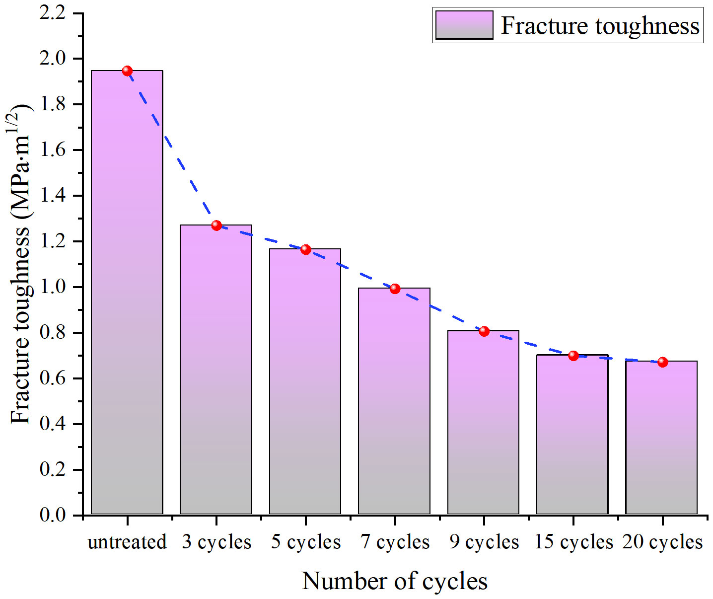
Figure 5 shows the Fracture toughness of samples under different cycles. In this study, the fracture toughness of granite was initially calculated to be 1.95 MPa·m1/2 without any treatment involving liquid nitrogen. After several liquid nitrogen treatments, the Fracture toughness of granite continuously decreased to 0.70 MPa · m1/2. It is obvious that the cracking resistance of granite tends to weaken after liquid nitrogen circulation. This could be attributed to changes in microstructures and stress distribution within the granite caused by the liquid nitrogen cycling, resulting in nonlinear variations in fracture toughness. Therefore, it is essential to consider the number of liquid nitrogen cycles during practical engineering construction to achieve optimal results.
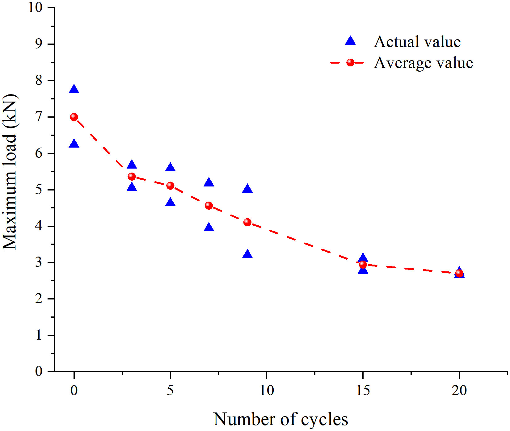
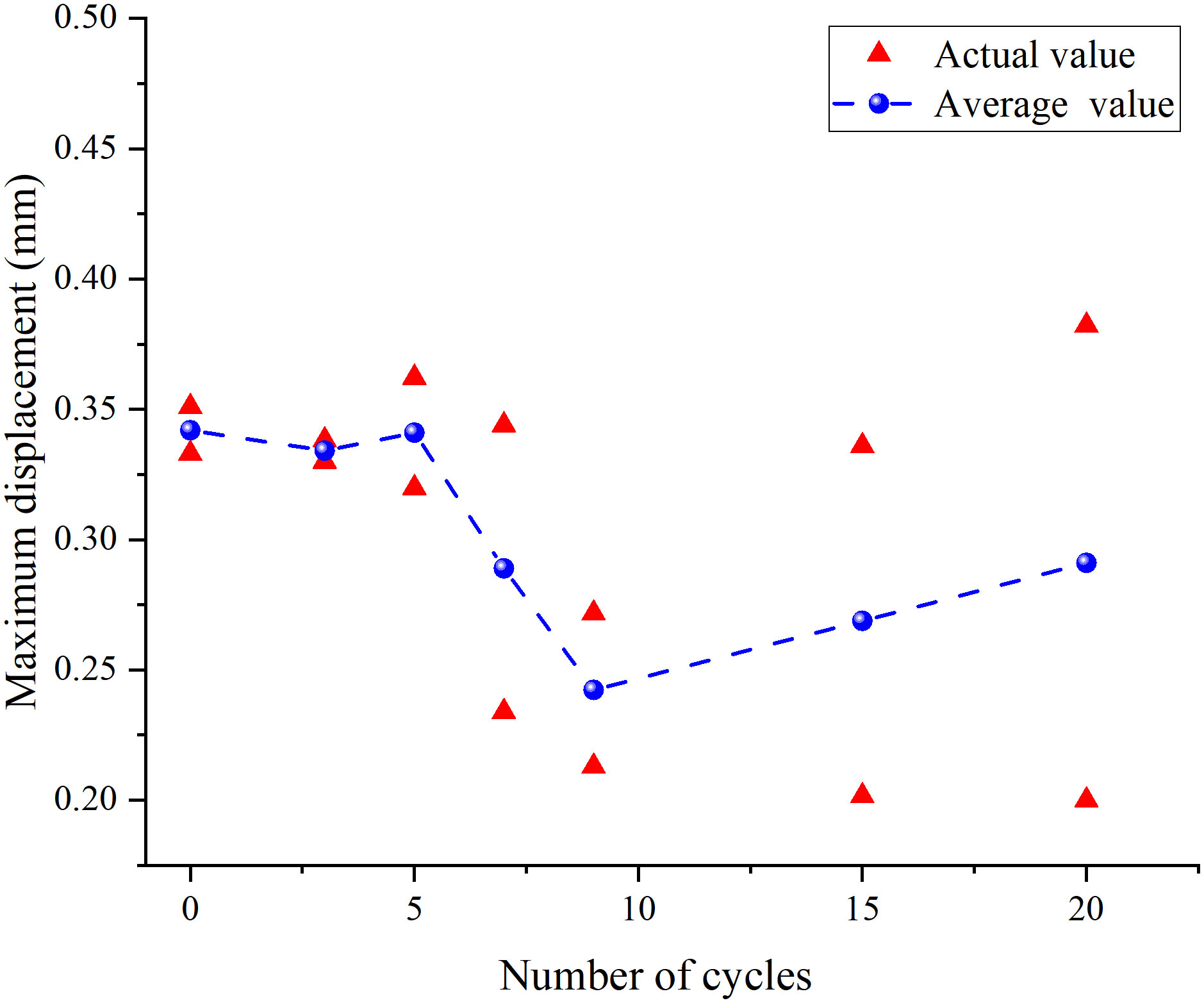
Through observation and analysis, it is evident that the untreated granite, serving as the control group, reached a peak load of 7742.1 N and a maximum displacement of 0.35 mm. The fracture toughness value determined at this specific point was K= 1.95 MPa·m1/2. After 3 cycles, the peak load increased to 5052.0 N, with a maximum displacement of 0.33mm, resulting in a fracture toughness of K=1.27 Mpa·m1/2. In the case of 5 cycles, the peak load reached 4630.2 N, with a maximum displacement of 0.35 mm, yielding a fracture toughness of K=1.16 Mpa·m1/2. For 7 cycles, the peak load reached 3946.2 N, with a maximum displacement of 0.23 mm, leading to a fracture toughness value of K=0.99 Mpa·m1/2. As for 9 cycles, the peak load reached 3206.4 N, with a maximum displacement of 0.21 mm, resulting in a fracture toughness of K=0.81 Mpa·m1/2. With 15 cycles, the peak load reached 2780.7 N, while the maximum displacement was 0.33 mm, leading to a fracture toughness value of K=0.70 Mpa·m1/2. Finally, after 20 cycles, the peak load reached 2670.0 N, with a maximum displacement of 0.38 mm, resulting in a fracture toughness of K=0.67 Mpa·m1/2.
By comparing Figures 4, 5, a distinct correlation can be observed between the variations in peak load and fracture toughness. First, regardless of the number of cycles, the load-displacement curve exhibits initial steady and gradual growth, followed by rapid ascent to the peak before sharply declining upon granite failure. This is a characteristic failure behavior of granite under three-point bending experimental conditions. From the comparison chart, it can be observed that, under the condition of 300°C, as the number of treatments rises, the maximum peak load shows a decreasing trend. This suggests that the mechanical properties of rocks weaken with an increase in the number of cycles. This could be attributed to the complex physical and chemical processes, such as the generation of microcracks and stress relaxation within the granite, resulting from thermal cycling, leading to nonlinear changes in its mechanical properties.
Figure 6 is the variation trend of load at the peak point of granite under different cycles. Based on Figure 6, it can be seen that, it can be seen that the mechanical properties of granite gradually exhibit a weakening trend with an increasing number of cycles. Firstly, analyzing the relationship between maximum load and cycle number, the average curve of maximum load for both sets of samples shows a downward trend. This suggests that granite undergoes an weakener in its mechanical properties after liquid nitrogen treatment. Excessive cycles of liquid nitrogen treatment noticeably weaken the mechanical properties of granite, and the more cycles performed, the more pronounced the weakening characteristics. This may be attributed to factors such as thermal stress and thermal shock generated within the granite after liquid nitrogen treatment, affecting its compressive strength and fracture toughness.
Additionally, an examination of the relationship between maximum displacement and cycle number reveals a same pattern. Figure 7 is the variation trend of displacement at the peak point of granite under different cycles. With an increasing number of cycles, the maximum displacement resulting from three-point bending displays an initial decrease followed by an increase. Moreover, as the number of cycles increases, the weakening characteristics become more pronounced. This phenomenon may be attributed to factors such as thermal expansion and contraction within the granite after liquid nitrogen treatment, resulting in changes in internal strain and displacement and thus affecting the plastic deformation capacity and fracture toughness of the granite. The variation pattern of load displacement at the peak point may be caused by the combined effect of liquid nitrogen effect and the mechanical properties of granite itself.
4 Analysis of acoustic emission characteristics of granite
4.1 Introduction of acoustic emission experiment
Materials, when subjected to external forces and temperature fluctuations, undergo deformation or fracture due to stress variations at structural defects. During this process, the material rapidly releases energy, generating a transient elastic wave and emitting sound. This phenomenon is known as acoustic emission (Grosse et al., 2021).
By analyzing the collected acoustic emission signals in experiments, the damage status of rocks during the loading process can be understood. The acoustic wave signals are precisely processed, and then damage assessment is conducted based on the variation patterns of characteristic parameters (Grosse et al., 2021). Parameter analysis is the most commonly used signal processing method. In this experiment, ring count and energy count are adopted as indicators for single-parameter analysis.
4.2 Acoustic emission characteristics of granite deformation and failure
To acquire acoustic emission data from high-temperature granite during the three-point bending process, a real-time acoustic emission acquisition system was employed. This system facilitated the collection of signals emitted by the granite as it underwent failure under different cycle numbers at a constant temperature. Figure 8 shows the acoustic emission ringing counts of granite under different cyclic conditions.
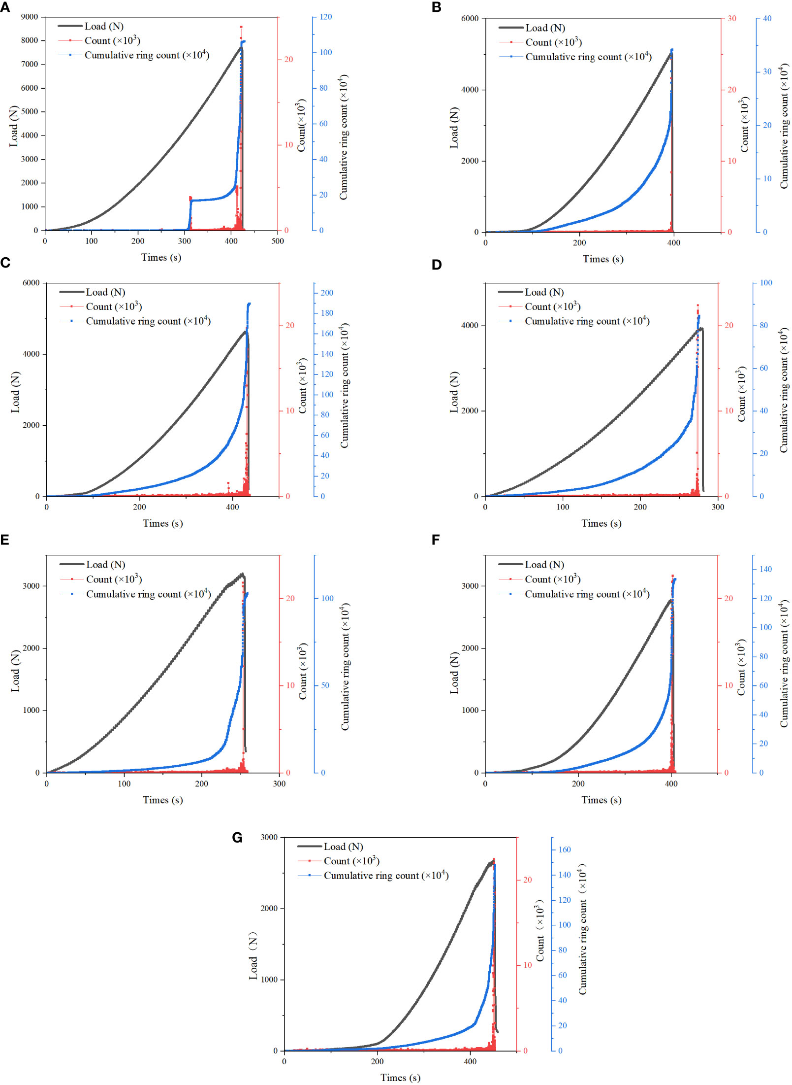
Figure 8 Ringing counts of granite under different cycle conditions:(A) untreated; (B) 3 cycles; (C) 5 cycles; (D) 7 cycles; (E) 9 cycles; (F) 15 cycles; (G) 20 cycles.
Upon analyzing the initial dataset, a clear correlation between the three stages of failure in the three-point bending process and the fluctuation in acoustic emission ring count was observed, as depicted in the Figure 8. During the initial elastic stage of granite loading, the damage is minimal, resulting in a low ring count rate and stable signals. The cumulative ring count curve exhibits slow and nearly horizontal growth. In this stage, the acoustic emission signals mainly arise from the closure of pre-existing cracks within the rock specimen and the sliding friction between rock particles. In the elasto-plastic deformation stage, the ring count signals remain inactive. However, compared to the elastic stage, events in this stage exhibit larger amplitudes, and the cumulative ring count gradually increases with an increasing slope in the curve. This is because granite, during this stage, achieves its optimal load-bearing state through the dislocation slip of microcracks and subtle adjustments in structure. Consequently, new microcracks and pores are generated within the granite, leading to an increase in acoustic emission signals.
During the stage of unstable crack propagation, which is close to the failure stage, as the loading continues, there is a sudden increase in the ring count, and the signals become active with the appearance of multiple sharp peaks. The cumulative ring count exhibits a rapid and concave-shaped growth, with both the magnitude of change and the slope of the curve increasing quickly. In this stage, the rock begins to fracture, leading to the generation, propagation, and connection of a large number of microcracks, forming macroscopic fractures. In this stage, the acoustic emission signals’ distinctive parameters exhibit a significant association with the level of rock failure, thereby offering valuable insights into the mechanisms and progression of rock failure.
During the stage of failure, the ring count signal exhibits a rapid increase, showing distinct bursts and pulsations. The cumulative ring count curve displays a steep increasing trend, corresponding to the peaks on the load-displacement curve. This phenomenon can be attributed to the extensive fracturing and fragmentation experienced by granite during this particular stage, leading to the substantial release of acoustic energy. Furthermore, during the failure stage, the ring count increases rapidly, reaching its peak at the moment when the curve descends, and the magnitude of the increase in the cumulative ring count is the greatest at this point. This indicates that the rock experiences large-scale fracturing and fragmentation, releasing tremendous acoustic energy. After the rock sample completely loses its load-bearing capacity and fails, the ring count rapidly decreases to zero as the stress within the rock mass is released. This finding suggests that no additional cracks or damages are generated within the rock during this stage, leading to the absence of further acoustic emission signals.
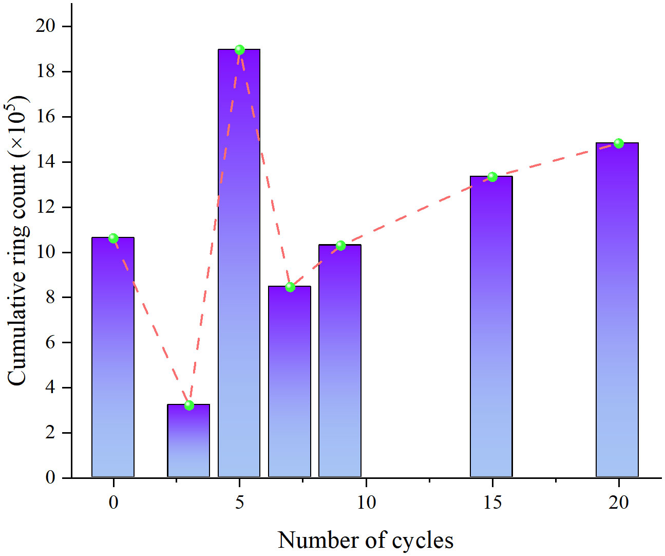
The analysis of the cumulative ring count and cycle number in Figure 9 reveals significant effects of liquid nitrogen on the granite. The trend displays a discernable pattern of initial decrease followed by subsequent increase, reaching its peak between 5 to 7 cycles. This indicates that the development of cracks and damages within the granite initially intensifies and then diminishes as the cycle number increases, with a peak occurrence between 5 and 7 cycles. The cumulative ring count of the liquid nitrogen-cooled granite exhibits a consistent trend that aligns closely with the load-displacement curve. Additionally, these signals can reflect the process and mechanisms of granite failure.
Figure 10 shows the acoustic emission energy counts of granite under different cyclic conditions. As depicted in the Figure 10, the variations in energy counting follow a similar pattern to that of ring counting, allowing for analysis across three distinct stages. During the stage of compression and densification of granite fissures, internal microcracks and pores gradually undergo closure due to pressure, resulting in low energy counting signals. The magnitudes of these signals are typically in the single digits, and the cumulative energy counting curve remains relatively unchanged with an almost horizontal slope. This suggests that, during this stage, the acoustic emission signals in granite mainly arise from the closure of pre-existing cracks and friction between particles, with minimal energy release. During the elastic-plastic stage, it is observed that the energy counting amplitude experiences a marginal increase while maintaining a relatively low level. Towards the end of this stage, the cumulative energy counting curve begins a gradual ascent. This indicates that new microcracks and pores are being generated in the granite, leading to an increase in energy release, albeit still at a relatively low level.
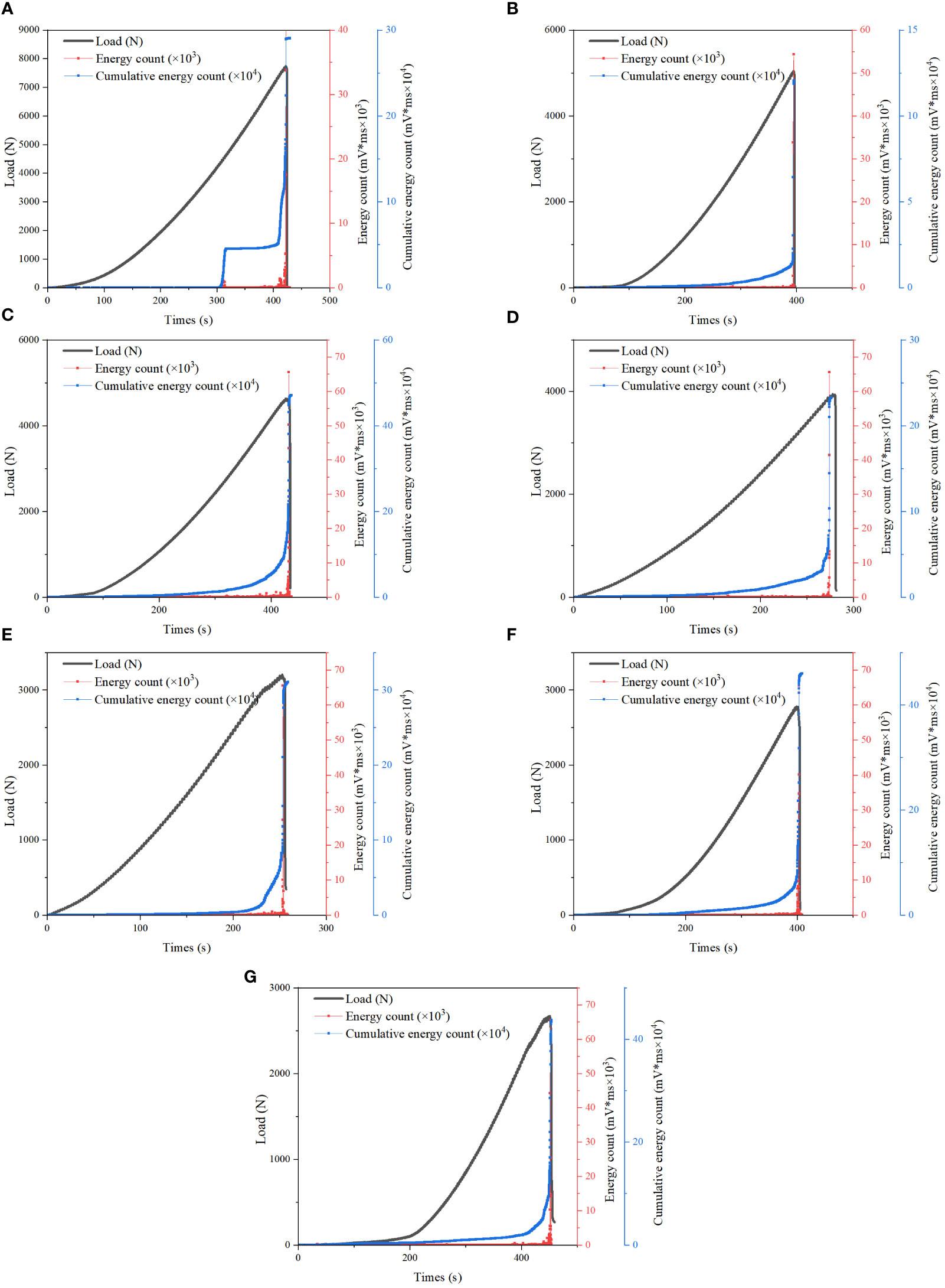
Figure 10 Energy counts of granite under different cycle conditions: (A) untreated; (B) 3 cycles; (C) 5 cycles; (D) 7 cycles; (E) 9 cycles; (F) 15 cycles; (G) 20 cycles.
During the stage of crack propagation, which is close to the point of failure, there is an increase in energy counting. The cumulative energy counting curve exhibits distinct abrupt points of rapid increase, with the cumulative values rising swiftly. At this stage, the rock begins to fracture, and a lot of microcracks generate, propagate, and connect to form macroscopic fissures. The magnitude of acoustic emission energy counting is mostly affected by two elements: the frequency of instantaneous acoustic emission events and the amount of strain energy released by the rock during the formation of microcracks. Therefore, it may be concluded that the granite has strong mineral particle connection before the cooling process. The bonds between some mineral particles, however, are broken after undergoing cryogenic cooling treatment due to thermal stress. As a result, there is an increased propensity for relatively stable microcracks to merge, which eventually results in unstable crack propagation and failure. This process is characterized by the release of a substantial amount of acoustic energy within the rock, resulting in a pronounced escalation in both energy counting and cumulative energy counting.
During the stage of failure, when the load-displacement curve undergoes a sudden decrease, the energy counting reaches a peak of magnitudes in the tens of thousands, and the cumulative energy counting exhibits the greatest variation at this point. This indicates that the rock undergoes extensive fracture and fragmentation during this stage, releasing tremendous acoustic energy. The rock specimen completely loses its bearing capacity, resulting in a macroscopic failure surface. It suggests that the rock no longer generates new cracks and damage during this stage, and the acoustic emission signals cease to occur. In this stage, the characteristic parameters of the acoustic emission signals exhibit a strong correlation with the rock’s failure strength, offering valuable insights into the magnitude and pattern of rock failure.
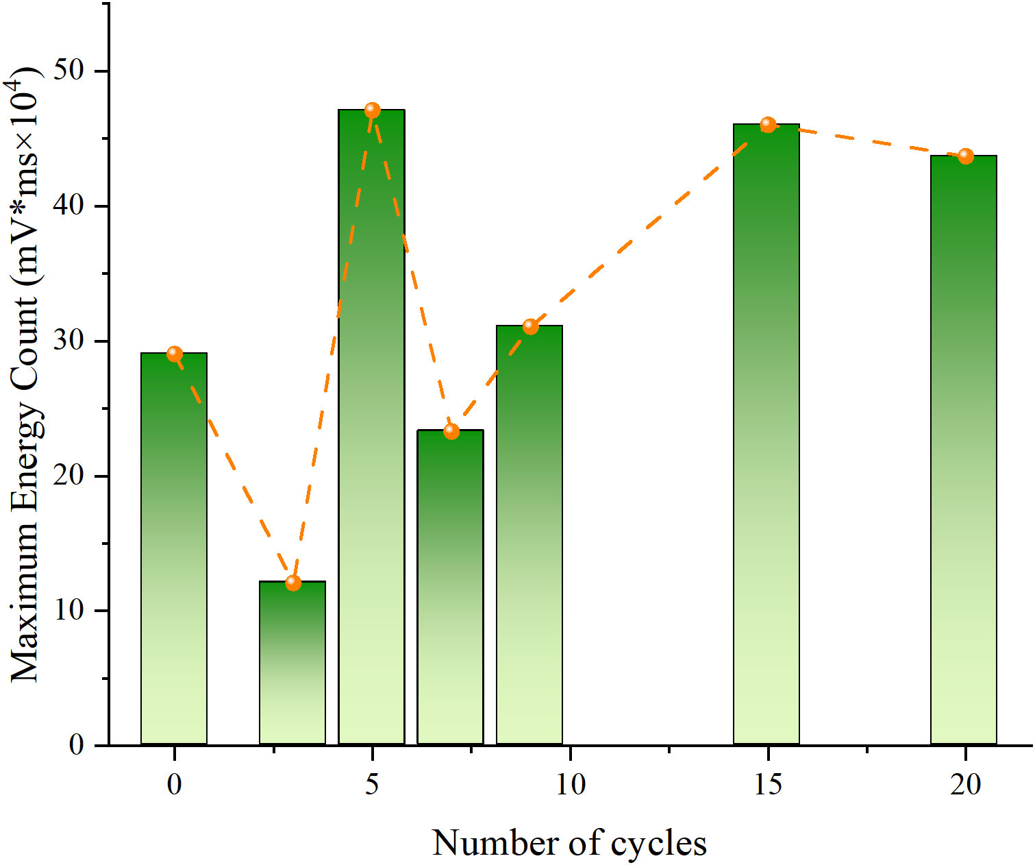
Analyzing the connection between the cumulative energy counting and the number of cycles in Figure 11, it is evident that the liquid nitrogen cooling treatment has an important impact on the cumulative energy counting of granite, exhibiting a trend of initial decrease followed by increase, with the maximum value reached between the 5th and 7th cycles. The cumulative energy counting exhibits an initial decrease followed by a subsequent increase as the number of cycles rises. This observation suggests that the release of internally generated acoustic energy in the granite follows a similar pattern, with the peak occurring between the 5th and 7th cycles. The cumulative energy counting of the granite, as influenced by the liquid nitrogen cooling treatment, exhibits a coherent trend that aligns closely with the load-displacement curve.
4.3 Classification of AE cracks
Firstly, the RA and AF values were calculated using data collected by sensors in acoustic emission experiments. Subsequently, a density plot was generated to analyze the differences in AF-RA distribution for different experimental conditions. We selected two sets of experimental results. To begin with, the analysis of the first dataset reveals the density plot of AF-RA data for granite obtained from the acoustic emission experiment, as illustrated in Figure 12. The analysis demonstrates that granite exhibits a wide range of AF values, predominantly falling between 0–400 kHz. This indicates that the acoustic emission signals of granite encompass various frequency components, reflecting the complexity of its internal structure and composition. Moreover, the majority of AE signals in granite possess low RA values, primarily below 40 μs/V. Furthermore, it is noteworthy that most of the high-density data points lie above the diagonal line, which signifies tensile failure in the rock, while data points below the diagonal line indicate shear failure. This observation implies that the main failure mechanism observed in the acoustic emission experiment for granite is predominantly tensile failure rather than shear failure.
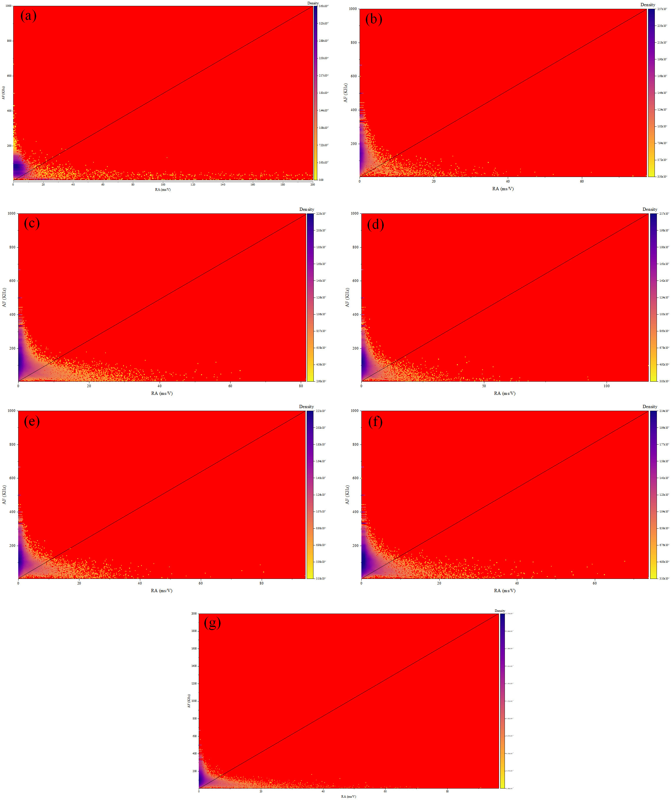
Figure 12 Distribution density map after treatment of different cycles in group 1: (A) untreated; (B) 3 cycles; (C) 5 cycles; (D) 7 cycles; (E) 9 cycles; (F) 15 cycles; (G) 20 cycles.
Lajtai (1969) proposed that in direct shear tests, jointed rock masses exhibit three primary modes of failure: shear failure, tensile failure, and compressive failure. Additionally, other relevant research has suggested that shear cracks constitute a significant proportion of microcracks formed during compressive tests (compressive failure) and dominate the fracture process. Drawing upon these prior findings and the acoustic emission characteristics observed in our study, it becomes apparent that during three-point bending tests, the rock experiences the formation of tensile cracks, shear cracks, and mixed-mode cracks, with tensile cracks being the predominant type of microcrack. Consequently, failure or flexural failure in such tests occurs primarily under a tensile-dominated state. These results highlight the distinct stress conditions and failure modes exhibited by rocks in three-point bending tests compared to direct shear tests and compressive tests.
Subsequently, the analysis of the second set of data yielded results that were largely consistent with those of the first set. Here, we provide a brief analysis: The density plot of AF-RA data for the granite obtained from the acoustic emission tests is presented in Figure 13. The analysis reveals that the AF values of the granite exhibit a wide distribution range, primarily between 0 and 400 kHz. Most of the AE signals recorded from the granite correspond to low RA values, predominantly below 40 μs/V. Furthermore, data points with medium to high density are predominantly located above the diagonal line, which indicates tensile failure, while those below the line reflect shear failure in the rock. These findings corroborate the outcomes derived from the initial dataset, suggesting that the three-point bending tests induce the development of various types of cracks in the granite, including tensile cracks, shear cracks, and mixed-mode cracks. Among them, tensile cracks emerge as the predominant form of microcrack. Consequently, the failure or flexural failure observed is primarily driven by tensile forces.
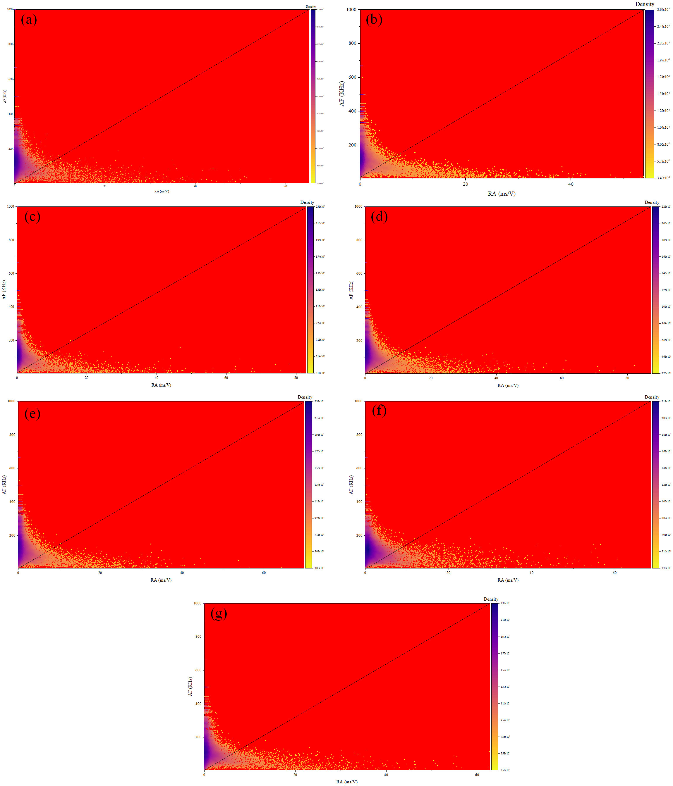
Figure 13 Distribution density map after treatment of different cycles in group 2: (A) untreated; (B) 3 cycles; (C) 5 cycles; (D) 7 cycles; (E) 9 cycles; (F) 15 cycles; (G) 20 cycles.
A three-point bending test on granite was conducted in this work to explore its fracture process using acoustic emission (AE) technology. A density plot of AE signals, specifically the Amplitude/Risetime ratio (RA) and average frequency (AF), was generated to analyze the variations in these parameters. The average frequency AF is the ringing count/duration. The experimental findings are as follows:
The average frequency (AF) of the granite exhibits a wide distribution range, primarily between 0 and 400 kHz, indicating that the AE signals of the granite consist of multiple frequency components. On the other hand, the amplitude/risetime ratio (RA) of the granite shows a narrow distribution range, mainly between 0 and 10. This implies that the AE signals in the granite are predominantly generated and propagated by the formation and extension of microcracks, rather than by the formation and propagation of macroscopic fissures.
The AF-RA density plot of the granite can be divided into three distinct regions, corresponding to different failure modes: tensile failure, shear failure, and mixed mode failure. The region associated with tensile failure is located in the lower left corner of the density plot, characterized by low RA and low AF signals. This indicates that tensile failure generates low-frequency and low-amplitude AE signals. On the other hand, the density plot reveals that the region linked to shear failure is situated in the upper right corner, distinguished by elevated RA and AF signals. This suggests that shear failure produces high-frequency and high-amplitude AE signals. The mixed mode failure region is situated in the middle part of the density plot, displaying moderate RA and moderate AF signals. This implies that mixed mode failure generates AE signals with intermediate frequencies and amplitudes.
And the AF-RA density plot of the granite is directly connected to its mechanical properties and can reflect the failure strength and mode of the granite. Generally, when tensile failure dominates in the granite, it exhibits lower strength, and the AE signals are concentrated in the lower left corner of the density plot. Conversely, when shear failure predominates in the granite, it demonstrates higher strength, and the AE signals concentrate in the upper right corner of the density plot. When the granite experiences mixed mode failure, its strength falls between the two aforementioned modes, and the AE signals are distributed in the middle part of the density plot.
5 Ultrasonic testing of granite
Porosity and longitudinal wave velocity are important physical parameters for evaluating the degree of internal structural damage in rocks. Ultrasonic detection experiments were carried out to test and analyze the pore structure of high-temperature granite under different cooling conditions. The experimental procedure employed a non-metallic ultrasonic testing and analysis instrument to transmit and receive ultrasonic signals through high-temperature granite samples. The non-metallic ultrasonic testing and analysis instrument was equipped with two sensor probes, capable of measuring parameters such as amplitude (dB), frequency (kHz), Ultrasonic Time (μs), and velocity (km/s). During testing, the two sensor probes were handheld, aligned with the specimen surface, and positioned in an inverted manner. Each specimen was subjected to three repetitions, and the average longitudinal wave velocity was calculated after excluding any outliers. The experimental results indicated a significant decrease in the longitudinal wave velocity of the cooled high-temperature granite, indicating changes in the internal pore structure of the rock.
After being subjected to liquid nitrogen cooling, high-temperature granite experiences significant changes in its internal pore structure and thermodynamic parameters. The application of thermal stress during the cooling process surpasses the tensile strength of the rock, leading to the initiation of new cracks and the propagation of existing ones. Consequently, damaged regions are formed within the rock. In order to investigate the patterns of pore structure changes in cooled high-temperature granite and the varying effects of different cooling methods on rock damage, ultrasonic longitudinal wave velocities were measured using a non-metallic ultrasonic testing and analysis instrument at various stages before and after heating.
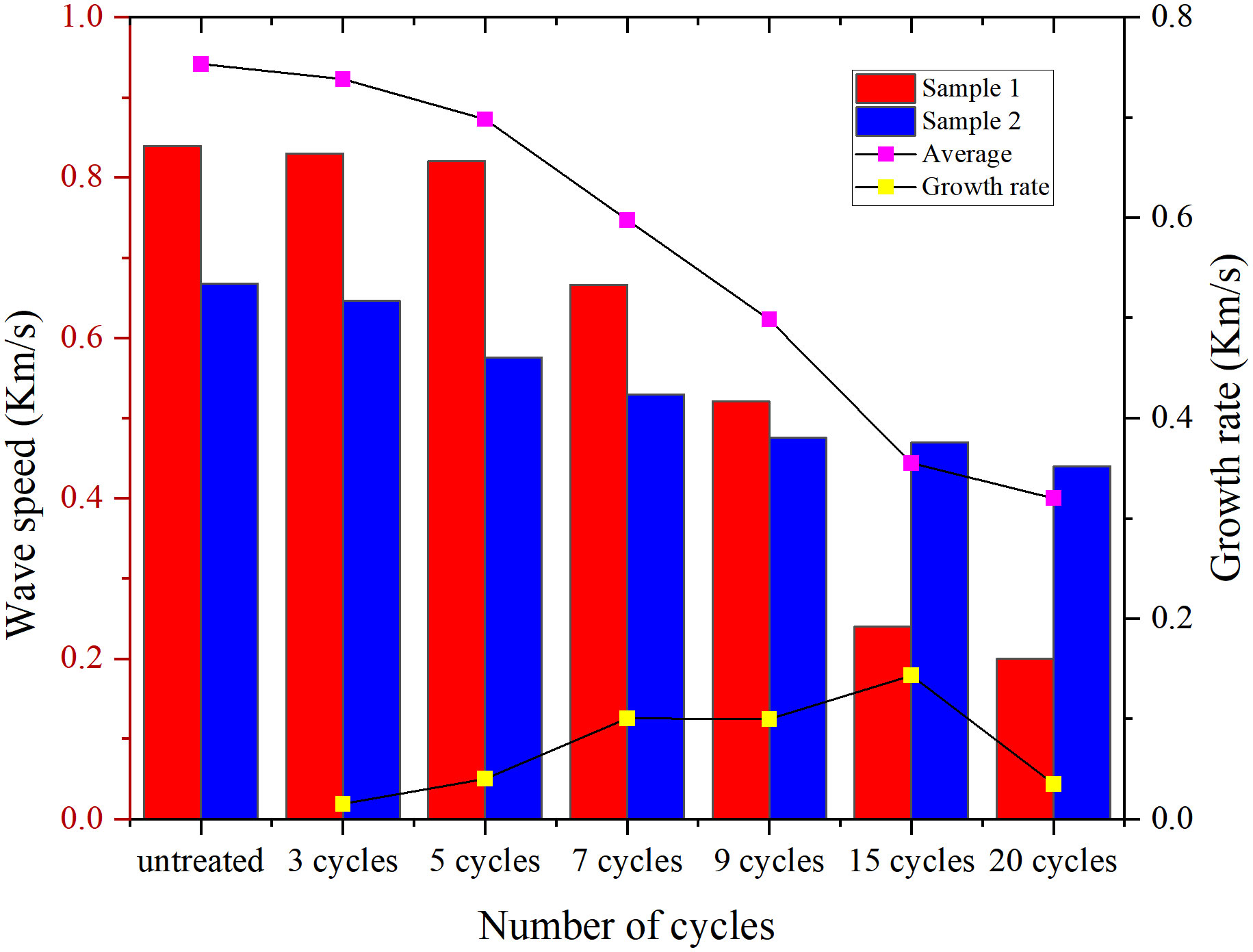
A comparison of the fluctuations in longitudinal wave velocity of granite specimens before and after different cycles of high-temperature treatment and liquid nitrogen cooling is given in Figure 14. Prior to the high-temperature cycles and liquid nitrogen cooling, there was little difference in the longitudinal wave velocity among the granite specimens. This was because we initially selected samples with similar wave velocities for the study using ultrasonic straight-through method, aiming to minimize the dispersion and heterogeneity among the specimens. The wave velocity of each specimen was immediately measured using ultrasonic straight-through method after being heated to 300°C in each cycle, and then compared with the results before the high-temperature cycles. After the cycles, a slight decrease in the longitudinal wave velocity was observed for each granite specimen. This is primarily attributed to the evaporation of free water in the internal pores of granite when it is heated, leading to an increase in porosity and a decrease in density.
The variation trend of longitudinal wave velocity for each granite specimen under different cycle numbers can be observed from Figure 14. Prior to the 7th cycle, the decay rate of longitudinal wave velocity for each granite specimen in both groups was relatively slow and slightly increased with increasing heating temperature and cooling rate. However, after the 7th cycle, a sharp decline in longitudinal wave velocity was evident for each granite specimen in both groups, with a significant increase observed as the heating temperature and cooling rate increased. This indicates that high-temperature granite undergoes significant physical changes and structural damage after being treated with liquid nitrogen cooling, transitioning from its original dense and brittle state to a loose and fragile state with increased ductility. Additionally, the thermal stress and strain induced by high-temperature and rapid cooling lead the generation of numerous defects within the granite and the enlargement of existing cracks and pore sizes.
6 Conclusion
The main purpose of this study is to investigate the mechanical behavior and damage effects of granite under the influence of liquid nitrogen. Firstly, the mechanical properties of the rock are explored through three-point bending tests with varying numbers of cycles. Secondly, the acoustic emission characteristics and energy evolution of the granite samples are studied using an acoustic emission monitoring system. The fracture mode of the granite is analyzed using AF-RA acoustic emission cloud mapping. Finally, the changes in internal fractures and pores of the granite are quantitatively analyzed using a non-metallic ultrasonic detector. The main conclusions are as follows:
(1) The load-displacement curve of granite can generally be separated into three sections. In the elastic stage, under the same temperature conditions, the more cycles there are, the slower the upward trend of the curve and the less significant the variations. In the elastoplastic deformation stage, the length and slope of the stage show different results influenced by the number of cycles. In the failure stage, the trend of the maximum load-bearing capacity of granite exhibits a similar pattern to the aforementioned stages. From the analysis of mechanical data, it can be observed that the peak strength of granite tends to decrease with an increasing number of liquid nitrogen cooling cycles. This indicates that different cycle numbers have a certain impact on weakening the mechanical performance of the rock at the same temperature.
(2) By analyzing the evolution pattern of acoustic emission (AE) signals in granite, we can identify several characteristics. In the initial compaction stage, the damage effect is weak, and the signal amplitude is low. In the elastic stage, the cumulative ring-down counts show a slow increasing trend, with significant increments and growth rates. In the elastoplastic stage, frequent AE events occur and multiple peak points appear, resulting in a rapid rise of the cumulative count curve that takes on a concave shape. In the failure stage, both types of signals experience sharp growth, with the maximum increment of the cumulative count curve reached. In tension or tension-dominant fractures, the AF-RA data distribution primarily falls within a rectangle along the long side of AF and the short side of RA. Conversely, in shear or shear-dominant fractures, the AF-RA data distribution mainly falls within a rectangle along the long side of RA and the short side of AF.
(3) Through ultrasonic testing experiments conducted on granite, it has been discovered that the longitudinal wave velocity of granite changes during the process of rock fracture, reflecting the microstructure and crack propagation inside the rock. As the number of cycles grows, the longitudinal wave velocity and splitting tensile strength of granite specimens gradually decrease, showing a decreasing trend. This indicates a reduction in the elastic modulus of granite and an intensification of damage. These observations imply significant alterations to the internal pore structure of the rock, potentially culminating in the generation or extension of cracks. Consequently, porosity increases while density decreases.
Data availability statement
The original contributions presented in the study are included in the article/supplementary material. Further inquiries can be directed to the corresponding authors.
Author contributions
LW: Methodology, Software, Writing – Original Draft. WZ: Conceptualization, Data curation. ZC: Writing – Reviewing and Editing. YX: Conceptualization, Data curation. JL: Writing – Reviewing and Editing. YZ: Visualization. CD: Software, Validation. TC: Software, Validation. All authors contributed to the article and approved the submitted version.
Funding
The authors are grateful to the financial support from the National Natural Science Foundation of China (52004082, 12002270, 52274096, 42007264, and 52174073), the Key Research and Development Program of Shaanxi Province, China (2022ZDLSF07-06, 2023-YBSF-369), and the Natural Science Basic Research Program of Shaanxi (2022JC-LHJJ-08).
Conflict of interest
Author TC is employed by the company Zibo Aojing Garden Co., Ltd.
The remaining authors declare that the research was conducted in the absence of any commercial or financial relationships that could be construed as a potential conflict of interest.
Publisher’s note
All claims expressed in this article are solely those of the authors and do not necessarily represent those of their affiliated organizations, or those of the publisher, the editors and the reviewers. Any product that may be evaluated in this article, or claim that may be made by its manufacturer, is not guaranteed or endorsed by the publisher.
References
Batchelor A. S. (1985). Progress in hot dry rock exploitation. Int. J. Energy Res. 9 (3), 377–390. doi: 10.1002/er.4440090312
Cai C. L., Gensheng I., Huang Z., Feng G. (2016a). Thermal cracking effect of liquid nitrogen on shale and its application analysis in hydraulic fracturing. J. China Univ. Petrol 40, 79–85. doi: 10.3969/j.issn.1673-5005.2016.01.0
Cai C., Huang Z., Li G., Gao F., Wei J., Li R. (2016b). Feasibility of reservoir fracturing stimulation with liquid nitrogen jet. J. Petrol. Sci. Eng. 144, 59–65. doi: 10.1016/j.petrol.2016.02.033
Cai C., Li G., Huang Z., Chi H. (2015). A waterless fracturing treatment: liquid nitrogen fracturing and its application prospect. Научные труды НИПИ Нефтегаз ГНКАР 3), 35–40. doi: 10.5510/OGP20150300250
Cha M., Yin X., Kneafsey T., Johanson B., Alqahtani N., Miskimins J., et al. (2014). Cryogenic fracturing for reservoir stimulation–Laboratory studies. J. petrol. Sci. Eng. 124, 436–450. doi: 10.1016/j.petrol.2014.09.003
Chen G., Sun Y., Xu Z., Li X. (2022). Hydrogeological feasibility of mine water deep geological storage in Baotashan coarse sandstone: A case study in Ordos Basin. Deep Underground Sci. Eng. 1 (2), 148–164. doi: 10.1002/dug2.12022
Chen Z., Xu G., Jiang M. (2019). The current status and development recommendations for dry hot rock fracturing technologies at home and abroad. Petrol. Drilling Tech. 47 (6), 1–8. doi: 10.11911/syztjs.2019110
Climo M., Carey B., Seward A., Bendall S. (2016). Strategies for increasing geothermal direct use in New Zealand. Proceed.: Geother. Resour. Council Trans 40, 689–694.
Coetzee S., Neomagus H. W., Bunt J. R., Strydom C. A., Schobert H. H. (2014). The transient swelling behaviour of large (– 20+ 16 mm) South African coal particles during low-temperature devolatilisation. Fuel 136, 79–88. doi: 10.1016/j.fuel.2014.07.021
Finnie I., Cooper G. A., Berlie J. (1979). Fracture propagation in rock by transient cooling. Int. J. Rock Mech. Min. Sci. Geomech. Abst. 16 (1), 11–21. Pergamon. doi: 10.1016/0148-9062(79)90771-X
Grosse C. U., Ohtsu M., Aggelis D. G., Shiotani T. (2021). Acoustic emission testing: Basics for research–applications in engineering (Springer Nature). Berlin, Springer-Verlag Berlin Heid
Grundmann S. R., Rodvelt G. D., Dials G. A., Allen R. E. (1998). “Cryogenic nitrogen as a hydraulic fracturing fluid in the devonian shale,” in SPE Eastern regional meeting. SPE–51067.
Guo Q. H., He T., Zhuang Y. Q., Luo J. L., Zhang C. H. (2020). Expansion of fracture network in granites via chemical stimulation: a laboratory study. Earth Sci. Front. 27 (1), 159. doi: 10.13745/j.esf.sf.2019.12.2
Hall K. (1999). The role of thermal stress fatigue in the breakdown of rock in cold regions. Geomorphology 31 (1-4), 47–63. doi: 10.1016/S0169-555X(99)00072-0
Hardy H. R. (1981). Applications of acoustic emission techniques to rock and rock structures: a state-of-the-art review. Acoustic emissions geotech. Eng. practice STP 750, 4–92.
Huang X. Q., Meng Q. K. (2018). Feasibility study on application of liquid nitrogen in hot dry rock drilling. Explor. Eng. (Rock Soil Drill Tunn) 45 (2), 22–25.
Huang Z. P., Zhang Y., Sun Y. K., Liu C. Y., Wu W. D. (2016). Mechanical and acoustic characteristics of high temperature limestone with water cooling treatment. J. Cent. South Univ. (Science Technology) 12, 4181–4189. doi: 10.11817/j.issn.1672-7207.2016.12.0
Kang H., Li W., Gao F., Yang J. (2023). Grouting theories and technologies for the reinforcement of fractured rocks surrounding deep roadways. Deep Underground Sci. Eng. 2 (1), 2–19. doi: 10.1002/dug2.12026
Kim K., Kemeny J., Nickerson M. (2014). Effect of rapid thermal cooling on mechanical rock properties. Rock mech. rock Eng. 47, 2005–2019. doi: 10.1007/s00603-013-0523-3
Lajtai E. Z. (1969). Shear strength of weakness planes in rock. Int. J. Rock Mech. Min. Sci. Geomech. Abst. 6 (5), 499–515. doi: 10.1016/0148-9062(69)90016-3
Li T. L., Cao W. J., Wang Y. W., Guo J., Jiang F. M. (2019). Laboratory study on hydraulic fracturing and acoustic emission monitoring of enhanced geothermal system. Adv. New Renewable Energy 7 (3), 241–248. doi: 10.3969/j.issn.2095-560X.2019.03.00
Li Z., Xu H., Zhang C. (2016). Liquid nitrogen gasification fracturing technology for shale gas development. J. Petrol. Sci. Eng. 138, 253–256. doi: 10.1016/j.petrol.2015.10.033
Liang M., Zhang S. H., Shu B. (2018). Effect of different cooling ways on Brazilian tension characteristics of heat-treated granite. J. Water Resour. Water Eng. 29 (2), 186–193. doi: 10.11705/j.issn.1672-643X.2018.02.3
Liu J., Xue Y., Fu Y., Yao K., Liu J. (2023). Numerical investigation on microwave-thermal recovery of shale gas based on a fully coupled electromagnetic, heat transfer, and multiphase flow model. Energy 263, 126090. doi: 10.1016/j.energy.2022.126090
Lu C., Wang G. (2015). Current status and prospect of hot dry rock research. Sci. Technol. Rev. 33 (19), 13–21. doi: 10.3981/j.issn.1000-7857.2015.19.00
Ma W., Wang Y., Wu X., Liu G. (2020). Hot dry rock (HDR) hydraulic fracturing propagation and impact factors assessment via sensitivity indicator. Renewable Energy 146, 2716–2723. doi: 10.1016/j.renene.2019.08.097
McDaniel B. W., Grundmann S. R., Kendrick W. D., Wilson D. R., Jordan S. W. (1997). “Field applications of cryogenic nitrogen as a hydraulic fracturing fluid,” in SPE Annual Technical Conference and Exhibition. SPE–38623.
Memon K. R., Mahesar A. A., Ali M., Tunio A. H., Mohanty U. S., Akhondzadeh H., et al. (2020). Influence of cryogenic liquid nitrogen on petro-physical characteristics of mancos shale: an experimental investigation. Energy Fuels 34 (2), 2160–2168. doi: 10.1021/acs.energyfuels.9b03700
Stephen R. (2013). In search of the waterless fracture. J. petrol. Technol. 65 (06), 46–54. doi: 10.2118/0613-0046-JPT
Wang P., Chen Y. L., Zhou X. L., Gao S. S., Zhao H. Z. (2013). Impact of rapid cooling in water on residual mechanical properties of granite under high temperature. J. Water Resour. Water Eng. 24 (3), 54–63.
Wang S. L., Li C. (2008). Reservoir technology in enhanced geothermal systems. Machinery Design Manufacture 9, 141–143.
Wang G. L., Liu Y. G., Zhu X., Zhang. W. (2020). The status and development trend of geothermal resources in China. Earth Sci. Front. 27 (1), 1. doi: 10.13745/j.esf.2020.1.1
Wang L., Xue Y., Cao Z., Wu X. J., Dang F. N., Liu R. (2023). Mechanical properties of high-temperature granite under liquid nitrogen cooling. Geofluids 2023, 3819799. doi: 10.1155/2023/3819799
Wu X., Huang Z., Li R., Zhang S., Wen H., Huang P., et al. (2018). Investigation on the damage of high-temperature shale subjected to liquid nitrogen cooling. J. Natural Gas Sci. Eng. 57, 284–294. doi: 10.1016/j.jngse.2018.07.005
Xu T., Zhang Y., Yu Z., Hu Z., Guo L. (2015). Laboratory study of hydraulic fracturing on hot dry rock. Sci. Technol. Rev. 33 (19), 35–39. doi: 10.3981/j.issn.1000-7857.2015.19.00
Xu T., Zhang Y., Zeng Z., Bao X. (2012). Technology progress in an enhanced geothermal system(Hot dry rock). Keji Daobao/ Sci. Technol. Rev. 30 (32), 42–45. doi: 10.3981/j.issn.1000-7857.2012.32.00
Xue Y., Liu S., Chai J., Liu J., Ranjith P. G., Cai C., et al. (2023a). Effect of water-cooling shock on fracture initiation and morphology of high-temperature granite: Application of hydraulic fracturing to enhanced geothermal systems. Appl. Energy 337, 120858. doi: 10.1016/j.apenergy.2023.120858
Xue Y., Ranjith P. G., Gao F., Zhang Z., Wang S. (2023b). Experimental investigations on effects of gas pressure on mechanical behaviors and failure characteristic of coals. J. Rock Mech. Geotech. Eng. 15 (2), 412–428. doi: 10.1016/j.jrmge.2022.05.013
Zhang S., Huang Z., Zhang H., Guo Z., Wu X., Wang T., et al. (2018). Experimental study of thermal-crack characteristics on hot dry rock impacted by liquid nitrogen jet. Geothermics 76, 253–260. doi: 10.1016/j.geothermics.2018.08.002
Zhang C. H., Wang L. G., Zhao Q. S., Li W. L. (2015). Permeability evolution model and numerical analysis of coupled coal deformation, failure and liquid nitrogen cooling. J. Hebei Univ. Sci. Technol. 36 (1), 90–99. doi: 10.7535/hbkd.2015yx01016
Keywords: liquid nitrogen, granite, mechanical properties, failure characteristics, acoustic emission, cracks
Citation: Wang L, Zhang W, Cao Z, Xue Y, Liu J, Zhou Y, Duan C and Chen T (2023) Effect of weakening characteristics of mechanical properties of granite under the action of liquid nitrogen. Front. Ecol. Evol. 11:1249617. doi: 10.3389/fevo.2023.1249617
Received: 29 June 2023; Accepted: 08 September 2023;
Published: 29 September 2023.
Edited by:
Liang Chen, China University of Mining and Technology, ChinaReviewed by:
Xiao Tan, Sichuan University, ChinaNing Li, Luoyang Institute of Science and Technology, China
Copyright © 2023 Wang, Zhang, Cao, Xue, Liu, Zhou, Duan and Chen. This is an open-access article distributed under the terms of the Creative Commons Attribution License (CC BY). The use, distribution or reproduction in other forums is permitted, provided the original author(s) and the copyright owner(s) are credited and that the original publication in this journal is cited, in accordance with accepted academic practice. No use, distribution or reproduction is permitted which does not comply with these terms.
*Correspondence: Zhengzheng Cao, Y2FvenoyMDA4QDEyNi5jb20=; Yi Xue, eHVleWlAeGF1dC5lZHUuY24=
 Linchao Wang1
 Zhengzheng Cao
 Yi Xue