 Baomin Liu1
 Dingchao Chen
94% of researchers rate our articles as excellent or good
Learn more about the work of our research integrity team to safeguard the quality of each article we publish.
Find out more
ORIGINAL RESEARCH article
Front. Earth Sci., 19 March 2025
Sec. Geohazards and Georisks
Volume 13 - 2025 | https://doi.org/10.3389/feart.2025.1566968
In the final mining phase of the working face, a large area of suspended roof can lead to stress concentration from mining-induced stress, which in turn causes deformation and instability of the main roadway. This study takes the Ji-17-21080 working face of the Pingdingshan No. 2 Mine as the engineering background, analyzing the structural characteristics of the main roof layer and the distribution of the advanced support stress, while revealing the principle of roof cutting and pressure relief for protecting the main roadway. Further, a FLAC3D numerical model was established based on the on-site geological conditions. The stress of the surrounding rock and the deformation characteristics of the main roadway were compared under four scenarios: (1) a stop-mining coal pillar width of 120 m (no roof cutting line), (2) a stop-mining coal pillar width of 60 m (no roof cutting line), (3) a stop-mining coal pillar width of 60 m with one roof cutting line, and (4) a stop-mining coal pillar width of 60 m with two roof cutting lines. The simulation results indicate that reducing the width of the stop-mining coal pillar significantly increases the mining-induced effects on the main roof. However, the implementation of roof cutting measures effectively interrupts the stress transmission path of the advanced support, improving the stress environment. Furthermore, compared to a single roof cutting line, the synergistic effect of two roof cutting lines is more beneficial. Finally, two roof cutting lines were designed for deep-hole blasting and pressure relief at the Ji-17-21080 working face. Field monitoring results showed that the deformation of the air return downhill remained within controllable limits, ensuring the safe operation of the next working face in the mining area.
Ongoing mining activities have led to the gradual depletion of shallow mineral resources, forcing resource extraction to advance deeper into the Earth’s interior (Kang et al., 2023; Sun et al., 2023; Yetkin et al., 2024; Zhu et al., 2024). At present, deep resource mining has become the new normal for resource development (Chen et al., 2022; Lyu et al., 2023; Cao et al., 2024; Chen D. et al., 2024; Jaiswal et al., 2024; Liu et al., 2024). However, deep mining activities face significant challenges, characterized by high temperature, high pressure, high ground stress, and disturbance effects (Wang and Miao, 2022; Zhang et al., 2022; Chen et al., 2024d). Particularly when deep coal mining faces enter the final mining phase, both the stop-mining coal pillar and the main roadway in front of the working face are subjected to dual disturbances from high in-situ stress and advanced support stress (Klishin et al., 2019; Chen et al., 2023; Zhang et al., 2024). To prevent structural instability of the main roadway due to these disturbances, the mining operations often increase the stop-mining coal pillar width to alleviate the impact of advanced support stress. However, this measure results in significant wastage of coal resources (Sun et al., 2021; Xie S. R. et al., 2022). On the other hand, if the stop-mining coal pillar width is narrow, the advanced support stress will be directly transmitted to the main roadway, posing a severe threat to the stress environment, potentially leading to instability and large deformation of the roadway (Yang et al., 2021; Li et al., 2023; Bednarek et al., 2024; Khademian and Sears, 2024).
The application of roof cutting technology, which actively disrupts the roof structure, has become a key technique for protecting the main roadway by effectively reducing the impact of advanced support stress (Liu B. et al., 2022; Vatandoust et al., 2023; Zhu et al., 2024; Huang B. X. et al., 2018) proposed the use of hydraulic fracturing technology to modify the roof structure and weaken its mechanical properties, creating weak fracture planes conducive to roof collapse, thereby controlling the collapse of the roof during the initial extraction phase. Field practices have shown that when the rear roof collapsed completely, it eliminates the shock hazards caused by the sudden collapse of the suspended roof in the mined-out area (Zhang et al., 2023). employed FLAC3D to investigate the stress evolution distribution under the influence of mining-induced stress and residual coal pillar stress during the final extraction phase. They proposed using hydraulic fracturing technology to sever the roof above the retreat roadway, thereby alleviating the manifestation of mining pressure and improving the stability of the retreat roadway and the safety of equipment evacuation (Chen et al., 2024c). addressed the issue of roadway being affected by both lateral support stress and advanced mining stress. They proposed a roof cutting technology centered on “hydraulic fracturing with directional and controllable cutting”. By severing the hard, suspended roof above the mined-out area, the stress concentration is reduced, ensuring the safety of the roadway (Yang et al., 2019). used pre-split blasting technology to cut the hard roof above the roadway, thereby weakening the stress transmission effect in the rock layers, and effectively controlling roadway deformation caused by complex stress environments. Field practices showed that the maximum working resistance of hydraulic supports decreased by 24.9%, and the surrounding rock deformation was significantly reduced (Zhang et al., 2020). proposed a new method for support in gob-side entry retaining based on focused explosive blasting for roof cutting. This method optimizes the roof structure and the evolution and distribution of stress, alters the stress transmission path, and thus protects the stability of the roadway. Monitoring results and field applications demonstrated reduced roadway convergence and significant pressure relief effects.
In summary, a wealth of research has been accumulated in the field of roof cutting and pressure relief (Ma et al., 2023; Shen et al., 2023). However, this technology has mainly been applied in scenarios such as gob-side roadway (Chen et al., 2024b; Wu et al., 2024; Yang et al., 2024). In contrast, research on roof cutting and pressure relief for protecting the main roadway at the location of the stop line remains relatively scarce. This paper uses the Ji-17-21080 working face of the Pingdingshan No. 2 Mine, owned by China Pingmei Shenma Group, as the engineering background. This study delves into the technology of deep-hole blasting in main roadway protection. A reasonable stop-mining coal pillar size and a corresponding blasting plan are proposed, and the effectiveness of roof cutting for main roadway protection is validated through practical application. The research findings provide valuable references and insights for maintaining main roadways in fully mechanized mining faces under similar conditions.
The surface elevation ranges from +252 m to +384 m, while the Ji-17-21080 panel elevation is between −371 m and −424 m. The depth of the Ji-17-21080 panel is approximately 700 m, with a strike length of 190 m. To the east, the working face connects to the air return downhill and haulage downhill of the No. 1 mining area, and to the west, it reaches the boundary of the mining field. The layout of the Ji-17-21080 working face is shown in Figure 1.
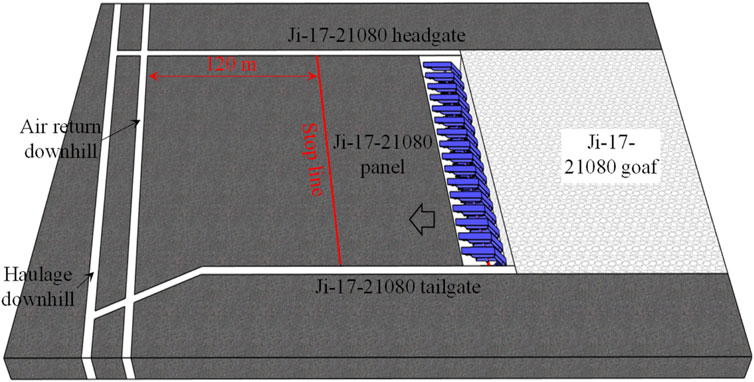
Figure 1. Layout of working face.
The borehole lithology profile is presented in Figure 2. The average thickness of the Ji-17 coal seam is 1.6 m, with a strike direction of 88°, and an average dip angle of 7.5°. The immediate roof is sandy mudstone (2.2 m), while the immediate floor is mudstone (3.0 m).
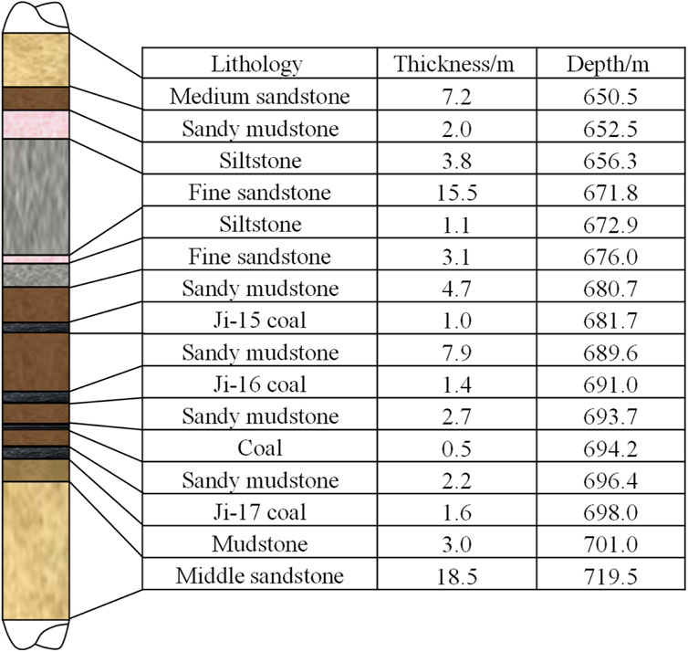
Figure 2. Borehole histogram.
According to the original mining plan, the width of the stop-mining coal pillar was set at 120 m (i.e., the distance from the stop line to the main roadway was 120 m), which resulted in a significant waste of resources. As shown in Figure 3, to improve the coal resource recovery rate, the decision was made to extend the working face by 60 m, optimizing the stop-mining coal pillar width to 60 m. However, this change has brought about the pressing issue of advanced support stress transmission, which needs to be addressed. To protect the air return downhill, roof cutting and pressure relief measures must be implemented.
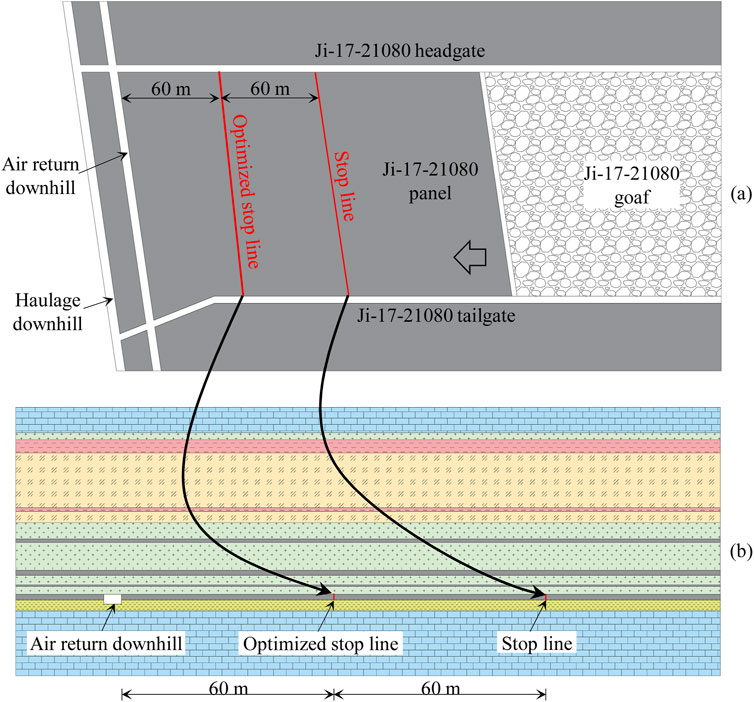
Figure 3. Optimization design of stop line: (A) plan view; (B) side view.
Before coal mining operations, the in-situ stress of the coal seams and surrounding rock layers is in a natural equilibrium state (Wang et al., 2023; Zhu and Wang, 2023). However, as mining progresses, the originally balanced in-situ stress environment is disrupted, leading to the formation of a new stress distribution (Ma et al., 2018). Coal mining alters the stress distribution borne by the coal seam, where the load previously supported by the coal seam is now transferred to the surrounding goaf area (Li Q. et al., 2024). As the mining-induced effects propagate, the stress gradually increases, where the advanced support stress and stress concentration phenomena become particularly prominent (Fu et al., 2024).
The distribution of advanced support stress can be divided into three zones: stress relief zone, stress increase zone, and stress stabilization zone. When the main roadway ahead of the working face is located in the stress increase zone, which can pose a significant threat to the roadway’s stability. The stress increase effect of advanced support stress can lead to roadway deformation, stress concentration, and even failure of the support structure. In severe cases, it may cause instability or collapse of the roadway (Liu X. et al., 2022; Hu et al., 2024). The distribution of advanced support stress is shown in Figure 4.
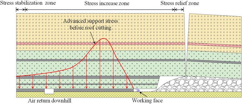
Figure 4. Distribution characteristics of advanced support stress.
In coal mining operations, if the thick and hard overburden strata above the goaf do not collapse promptly, large suspended roof areas may form, leading to increased stress concentrations and posing threats to the stability of the main roadway. To address this issue, two roof cutting methods are introduced, corresponding to the first and second roof cutting lines.
During coal mining operations, if the thick and hard overburden strata above the goaf do not collapse in a timely manner, a large area of suspended roof may form (Huang B. et al., 2018; Li L. et al., 2024). Such suspended roof zones cause the load from the overburden to transfer to the solid coal layers, significantly increasing the peak value of advanced support stress and expanding its influence range (Tu et al., 2022). This concentration of stress not only worsens the stress environment near the working face but can also pose a serious threat to the stability of the main roadway (Xie S. et al., 2022).
To effectively mitigate this issue, roof cutting technology can be employed (Zhang et al., 2020; Xu et al., 2024). This involves forming continuous cutting seams within the thick, hard rock layers near the stop line. The technology uses deep-hole drilling followed by precise blasting within the rock layers to create a series of cutting seams, aimed at disrupting the integrity of the suspended roof. When the working face reaches the stop line, the thick and hard roof above the goaf, under the influence of mining-induced stress, will slide along the deep-hole pre-split seams into the goaf, thereby reducing the peak value and influence range of the advanced support stress. The distribution of advanced support stress after roof cutting at the stop line is shown in Figure 5.
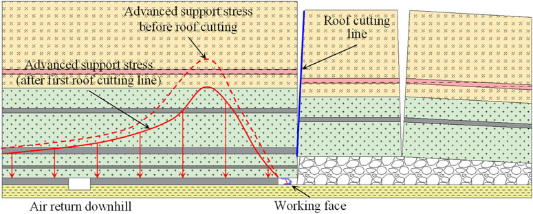
Figure 5. Distribution of advanced support stress after roof cutting at the stop line.
Advanced support stress is characterized by its wide propagation range and significant impact. Therefore, to enhance the roof cutting effect, roof cutting can also be performed within the stop-mining coal pillar in addition to the stop line.
By conducting deep-hole blasting, the full power of the blasting is utilized to disrupt the integrity of the rock layers, forming blast cavities and fracture zones within the rock mass. This pre-splitting technique effectively breaks the intact structure of the rock layers and disrupts the continuity of the original rock mass, thereby interfering with the transmission process of advanced support stress.
During the propagation of advanced support stress, the fractured rock mass on both sides of the fracture zone behaves like a “sponge”. The bearing capacity in the center of the fracture zone is greatly reduced, resulting in a pressure relief effect that causes the load, which would have been transmitted to the rock mass on either side, to concentrate on the two sides of the fracture zone. This process can effectively weaken stress propagation within the fracture zone and create stress concentration phenomena on both sides of the zone, similar to a fault with no vertical displacement. Since the coal and rock mass within the fracture zone has been highly fragmented, it can significantly reduce the transmission of advanced support stress and provide a certain degree of stress blocking. The distribution of advanced support stress after roof cutting within the stop-mining coal pillar is shown in Figure 6.
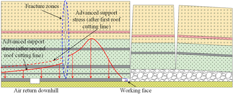
Figure 6. Distribution of advanced support stress after roof cutting in the stop-mining coal pillar.
Based on the concept of the bearing arch proposed by Wang et al. (2024), during the advancement of the working face, the overlying strata not only form an arch structure in the direction of the coal seam dip but also exhibit a similar structure in the direction of the working face advancement. As the working face progresses, the scope of the bearing arch gradually expands. The internal, stable rock layers progressively extend upwards towards the overlying strata, and delamination within the strata continues to propagate dynamically in the upper layers.
The bearing arch is simplified to a three-hinged arch structure, as shown in Figure 7A. In this model, the height of the bearing arch is h, the span is b, the length of the working face is l, the horizontal distance between the arch foot and the roadway side is a, and the thickness of coal seam is m.
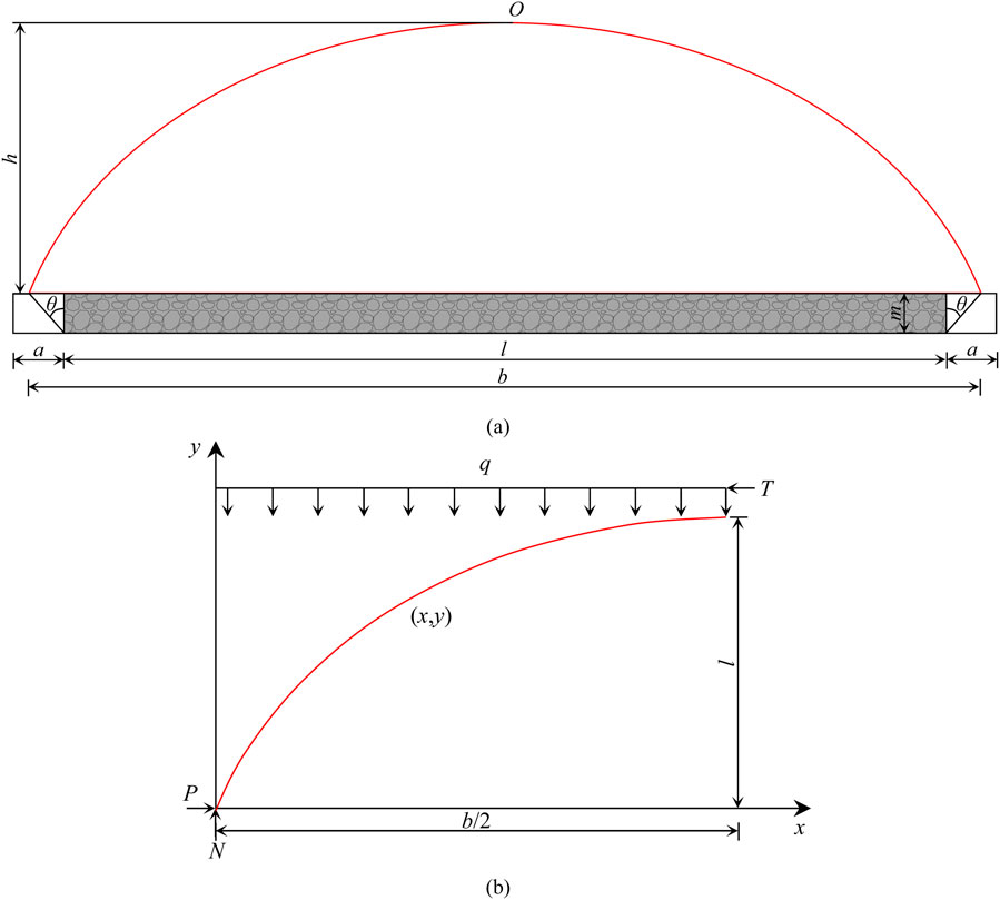
Figure 7. Schematic analysis of the bearing arch mechanical model: (A) bearing arch structure mechanical model; (B) force analysis of the bearing arch.
Since the model is symmetrical, only one side is analyzed, as illustrated in Figure 7B. The upper part of the arch is subjected to a uniform distributed load q, with horizontal tangential support force T at the arch crown, and reaction forces P and N at the arch foot.
Assuming the three-hinged arch is in a stable, moment-free state, the force equilibrium yields the following equations:
Among them:
where, f represents the apparent friction coefficient (referencing the overburden strength coefficient). To ensure sufficient stability of the arch in the horizontal direction, it must be ensured that T < P. With a safety factor of 2, the system of Equations 3, 5 is solved to obtain:
The equation of the axis of the bearing arch at any point (x, y) can be derived as:
The angle θ between the slip plane of the coal wall crack and the coal wall side at the lower part of the goaf is given by the active rock mass pressure theory:
where, φ is the friction angle of the overlying strata.
By solving Equations 2, 5, 6 simultaneously, the height of the bearing arch (h) can be expressed as:
Based on the Ji-17-21080 working face parameters and the mechanical model of the bearing arch, where the working face length l = 190 m, the average thickness of weak rock layers m = 1.6 m, the friction angle φ = 28°, and f is taken as 2.2 to 2.5, the calculated height of the bearing arch for the working face overburden is found to range from 38.0 m to 43.1 m.
A numerical model is established using FLAC3D, with model dimensions of 200 m in width and 76.2 m in height, as shown in Figure 8. The cross-sectional dimensions of the air return downhill are 5.0 m × 2.8 m. A 16.0 MPa load is applied to the top of the model, while the bottom and sides of the model are fixed to prevent displacement. A lateral stress coefficient of 1.2 is applied. The Mohr-Coulomb model is used to simulate the behavior of each rock layer. The mechanical parameters of the model are listed in Table 1.
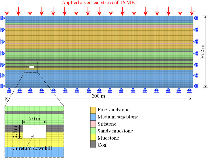
Figure 8. Numerical model.
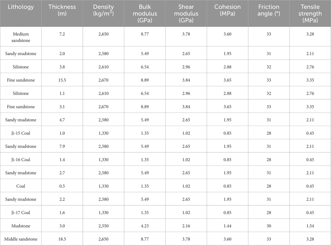
Table 1. Mechanical parameters of the model.
To verify the feasibility of the optimized stop line and the impact of roof cutting lines on the main roadway, four simulation schemes were designed, as detailed in Table 2. In these schemes, the roof cutting height is set to reach the fine sandstone (15.5 m). The models for the four schemes are shown in Figure 9.
Case 1: The pillar width is 120 m, with no roof cutting line.
Case 2: The pillar width is 60 m, with no roof cutting line.
Case 3: The pillar width is 60 m, with the first roof cutting line located 10 m behind the stop line.
Case 4: The pillar width is 60 m, with the first roof cutting line located 10 m behind the stop line, and the second roof cutting line placed 20 m ahead of the air return downhill.
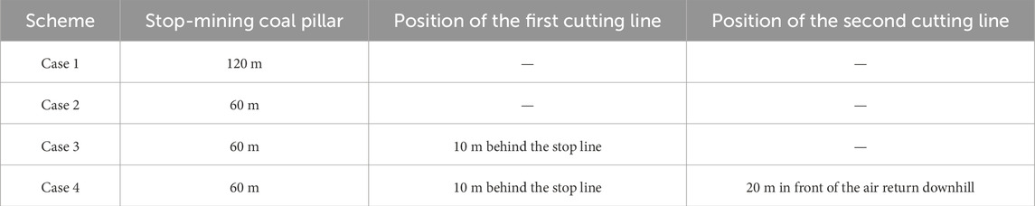
Table 2. Simulation scheme.
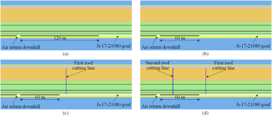
Figure 9. Simulation scheme: (A) case 1; (B) case 2; (C) case 3; (D) case 4.
The specific simulation process is shown in Figure 10. The numerical simulation work is divided into three stages:
(1) Excavation of the air return downhill: The air return downhill is excavated, and the model is run until equilibrium is achieved, simulating the excavation phase of the main roadway.
(2) Setting the roof cutting line: The roof cutting line is simulated using the interface function in FLAC3D. If no roof cutting line is included in the scheme, this step is skipped.
(3) Excavation of the Ji-17-21080 working face: Excavation begins from the right side and proceeds gradually to the left, simulating the mining process of the Ji-17-21080 working face. Each excavation step advances by 2 m, continuing until the predetermined stop line is reached.

Figure 10. Simulation process.
The vertical stress distribution contours for different schemes are shown in Figure 11.
(1) Stop-mining coal pillar width = 120 m
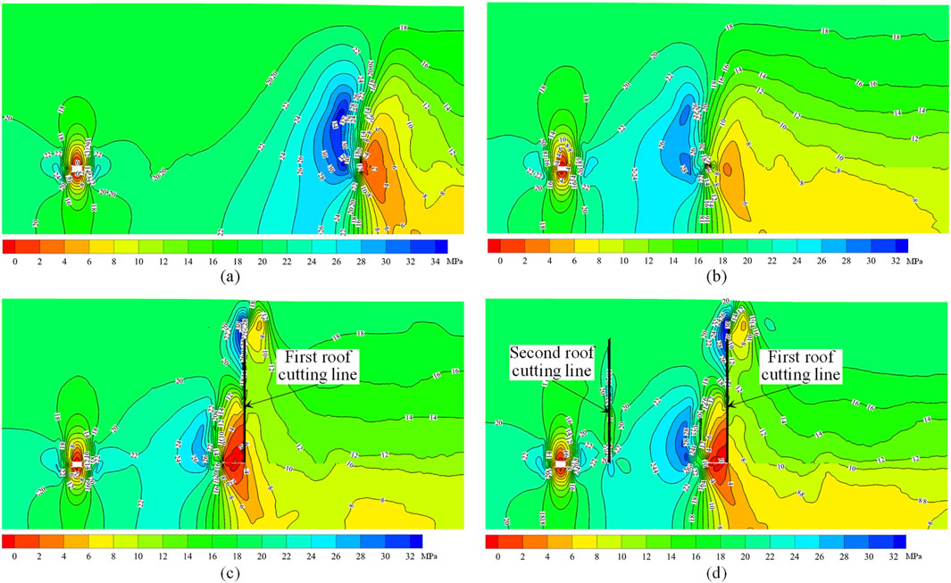
Figure 11. Vertical stress distribution cloud map: (A) case 1; (B) case 2; (C) case 3; (D) case 4.
In this case, the advanced support stress is primarily concentrated within a 10-15 m range ahead of the stop line, and the stress impact gradually decreases as one moves further left from the stop line. Because the pillar width is large, the distance between the stop line and the main roadway is also greater, resulting in a relatively small mining-induced impact on the air return downhill. This indicates that under conditions with a wider stop-mining coal pillar, the stress environment around the air return downhill is relatively stable, and the transmission of mining-induced stress has a limited effect.
(2) Stop-mining coal pillar width = 60 m
With a significant reduction in the pillar width, the mining-induced stress on the air return downhill increases significantly. At this point, the influence of mining-induced stress from the Ji-17-21080 working face overlaps with the excavation impact zone of the air return downhill, resulting in a substantial increase in the stress borne by the stop-mining coal pillar. Compared with case 1, the stress environment around the air return downhill is overall much higher, which increases the potential safety risks. This suggests that a narrower stop-mining coal pillar may lead to greater stress concentration and instability in the surrounding rock.
(3) Stop-mining coal pillar width = 60 m, with first roof cutting line
Compared to case 2, the installation of the first roof cutting line effectively blocks part of the mining-induced stress transmission, significantly reducing the mining-induced impact on the air return downhill. Meanwhile, the stress concentration inside the stop-mining coal pillar also decreases. The peak stress zone shifts from the area ahead of the stop line towards the depth of the roof and is mainly concentrated near the roof cutting line. This phenomenon indicates that the first roof cutting line can effectively sever the transmission path of advanced support stress, improving the stress environment and enhancing the stability of air return downhill.
(4) Stop-mining coal pillar width = 60 m, with two roof cutting lines
Compared to case 3, the installation of the second roof cutting line further blocks the transmission of mining-induced stress. At this point, the air return downhill is almost no longer affected by the advanced support stress. The stress is mainly concentrated within the 40 m coal pillar between the two roof cutting lines. Since this portion of the coal pillar is no longer mined and is far from the air return downhill, the stress environment near the air return downhill is significantly improved under the synergistic effect of the two roof cutting lines. Additionally, the support stress is effectively controlled within the two roof cutting lines.
A measurement line, 60 m in length, was arranged from the center of the right rib of the air return downhill to the right, to monitor the vertical stress under different schemes. The results are shown in Figure 12. The vertical stress distribution curves provide a more intuitive view of the variations and numerical values of stress under the four different schemes.
Case 1: In this case, the vertical stress distribution along the measurement line shows a single peak pattern, with higher stress on the left and gradually decreasing stress on the right. This indicates that with a larger stop-mining coal pillar width, the influence of stress gradually weakens, and the stress environment around the air return downhill remains relatively stable.
Cases 2 and 3: In these cases, the vertical stress distribution pattern changes significantly, exhibiting a double peak pattern with lower stress on the left and higher stress on the right. This change reflects the influence of a smaller stop-mining coal pillar width, which leads to stress concentration near the working face. Notably, compared to case 2, case 3 shows a reduction in the overall stress values, which strongly indicates that the first roof cutting line plays a significant role in alleviating the transmission of stress.
Case 4: In this case, the vertical stress distribution shows a more complex triple peak pattern. Compared to cases 2 and 3, a new stress peak appears near the second roof cutting line. Although the second roof cutting line causes some stress concentration, it effectively interrupts the transmission of stress, significantly reducing the stress in the area between the air return downhill and the second roof cutting line. The stress environment in this area almost returns to the level observed in case 1. Therefore, the second roof cutting line further optimizes the stress distribution in the surrounding rock.
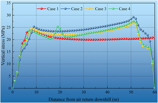
Figure 12. Vertical stress distribution curve.
From a quantitative perspective, the stress peaks on the right side of the air return downhill under the four schemes are as follows: 23.8 MPa (case 1), 25.3 MPa (case 2), 24.5 MPa (case 3), and 23.9 MPa (case 4). These data indicate that the stress environment in case 1 and case 4 is relatively better, with case 4 showing significant improvement in stress due to the effect of the second roof cutting line.
Considering the stress distribution in all four schemes, the stress environment, ranked from best to worst, is as follows: case 1, case 4, case 3, and case 2. This result indicates that appropriate arrangement of roof cutting lines can significantly improve the stress environment, especially when the pillar width is smaller, where the role of roof cutting lines is particularly crucial.
The distribution of vertical displacement of the surrounding rock for different schemes is shown in Figure 13.
(1) Stop-mining coal pillar width = 120 m
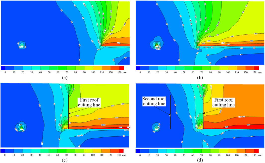
Figure 13. Vertical displacement distribution cloud map: (A) case 1; (B) case 2; (C) case 3; (D) case 4.
After the mining of the Ji-17-21080 working face, the rock mass above the roof collapsed progressively from the bottom upwards. The area with severe surrounding rock deformation is mainly concentrated above the mined-out area. Overall, the deformation of the air return downhill is minimal, indicating that under the condition of a wider stop-mining coal pillar, the stability is relatively good, and the impact of mining disturbance is limited.
(2) Stop-mining coal pillar width = 60 m
After the mining of the Ji-17-21080 working face, the influence range of surrounding rock deformation extended to the left, significantly increasing the deformation area. Particularly, the surrounding rock deformation around the air return downhill increased noticeably, highlighting the adverse impact of a narrower stop-mining coal pillar width on the stability of the roadway.
(3) Stop-mining coal pillar width = 60 m, with first roof cutting line
After setting the first roof cutting line, there was a marked difference in the deformation of the surrounding rock on both sides of the roof cutting line. The deformation on the right side of the roof cutting line was greater, while the deformation on the left side was smaller. This indicates that the roof cutting line had a significant effect on controlling the surrounding rock deformation. Compared to Scheme 2, the surrounding rock deformation around the air return downhill decreased, further verifying the suppressive effect of the roof cutting line on the deformation of the surrounding rock.
(4) Stop-mining coal pillar width = 60 m, with two roof cutting lines
Under the combined effect of two roof cutting lines, the mining-induced disturbance to the surrounding rock deformation was further reduced. The areas with significant surrounding rock deformation were effectively confined to the mined-out area above and a certain range in front of the stop line. The surrounding rock deformation around the air return downhill was overall lower, indicating that the setting of two roof cutting lines better controlled the surrounding rock deformation and improved roadway stability.
The deformation of the main roadway’s roof, two ribs, and floor under the four schemes is further analyzed, as shown in Figure 14.
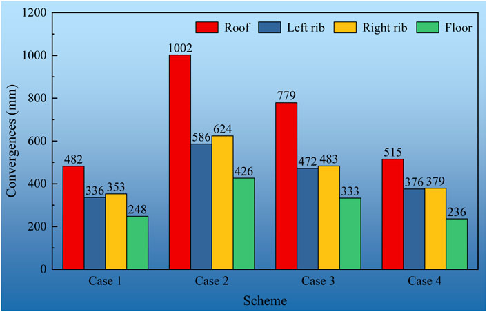
Figure 14. Deformation statistics of roadway.
For all four schemes, the deformation trends of the roadway remain consistent, with the roof exhibiting the greatest deformation, followed by the left rib, the right rib, and the floor, which experiences the least deformation.
Case 1: The deformation values for the roof, left rib, right rib, and floor are 482, 336, 353, and 248 mm, respectively.
Case 2: The deformation values for the roof, left rib, right rib, and floor are 1,002, 586, 624, and 426 mm, respectively. Compared to case 1, the deformations increased by 107.8%, 74.4%, 76.8%, and 71.8%, respectively.
Case 3: The deformation values for the roof, left rib, right rib, and floor are 779, 472, 483, and 333 mm, respectively. Compared to case 2, the deformations decreased by 22.3%, 19.5%, 22.6%, and 21.8%, respectively.
Case 4: The deformation values for the roof, left rib, right rib, and floor are 515, 376, 379, and 236 mm, respectively. Compared to case 2, the deformations decreased by 48.6%, 35.8%, 39.3%, and 44.6%, respectively.
From the statistical results, it is evident that reducing the stop-mining coal pillar width significantly increases the deformation of the air return downhill. The implementation of roof cutting measures reduces this deformation, with the effect being more pronounced when two roof cutting lines are applied, as opposed to just one. This finding demonstrates that reasonable placement of roof cutting lines can significantly improve the deformation conditions of the surrounding rock, thereby enhancing roadway stability.
This study investigates the significant impact of stop-mining coal pillar width and roof cutting measures on the stress and deformation characteristics, shedding light on their crucial role in roadway stability.
Firstly, the width of the stop-mining coal pillar has a significant effect on stress and deformation. When the pillar width is large (e.g., Case 1, with a 120 m width), the distance over which mining-induced stress is transmitted is limited. As a result, the stress environment around the air return downhill remains relatively stable, and deformation is minimal. This indicates that a wider stop-mining coal pillar effectively reduces the impact of mining activities on the main roadway, thus maintaining better roadway stability. However, when the pillar width is reduced to 60 m (e.g., Case 2), the mining-induced stress increases significantly, leading to a marked increase in stress and deformation, particularly around the air return downhill. This escalation in stress and deformation heightens the risk of roadway instability.
Secondly, roof cutting measures play an essential role in mitigating mining-induced stress transmission and optimizing the stress environment. By setting up roof cutting lines (e.g., Cases 3, 4), the transmission path of the advance support stress from the working face can be effectively severed, reducing the impact of mining on the air return downhill. Particularly when two roof cutting lines are employed (Case 4), stress transmission is more effectively controlled, confining mining effects within the coal pillar. This significantly improves the stress environment around the roadway, reduces stress peaks, and minimizes surrounding rock deformation. These results highlight the importance of the roof cutting line arrangement, especially when the stop-mining coal pillar width is smaller, where roof cutting measures are particularly critical.
Lastly, compared to a single roof cutting line, the synergistic effect of two roof cutting lines demonstrates a more significant improvement. In Case 4, the two roof cutting lines not only effectively block the transmission of mining-induced stress from the right-side working face but also significantly reduce the stress and deformation near the air return downhill. While localized stress concentration occurs near the second roof cutting line, overall, this measure greatly enhances the surrounding rock’s stress distribution, leading to a marked improvement in roadway stability. This emphasizes that the strategic placement of roof cutting lines, especially multiple roof cutting lines, is an effective measure for enhancing roadway stability and safety.
The rationality of the deep-hole blasting roof cutting position directly affects the unloading effect. The primary objective is to reduce the influence range of the advance support stress while minimizing the peak value of this stress to mitigate its impact on the working face.
Based on the above analysis results, the first roof cutting line is arranged 10 m behind the optimized stop-mining line of the Ji-17-21080 working face, and the second roof cutting line is placed 20 m ahead of the air return downhill. According to the lithological distribution of the roof, the roof cutting height should reach the fine sandstone layer. The locations of the roof cutting lines are shown in Figure 15.
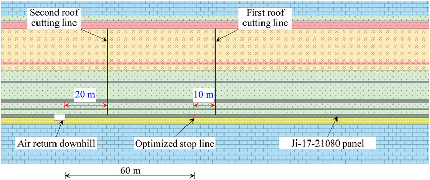
Figure 15. Deep-hole blasting cut-off design for ji-17-21080 working face.
Both the first and second roof cutting lines adopt the same borehole arrangement. They are fan-shaped, with boreholes drilled from the Ji-17-21080 tailgate and the Ji-17-21080 headgate toward the center of the working face. A total of 14 boreholes are arranged in the tailgate and headgate, with 28 boreholes for each roof cutting line. The specific arrangement of the blasting holes is shown in Figure 16, with the blasting hole parameters listed in Table 3.
Figure 16. Plan view of the first and second roof cutting blasting hole.
Table 3. Drilling layout parameters.
The on-site deep-hole pre-splitting blasting construction process consists of five main steps: connecting the explosives, loading the explosives, sealing the holes, connecting the detonating cords, and initiating the blast. The specific construction steps are illustrated in Figure 17.
Figure 17. Construction process flow.
The effects of the blasting are shown in Figure 18. After the blasting, distinct blast-induced fractures are visible on the roof, with well-defined and orderly cracks, as well as an effective cutting effect. This also indicates that the blasting technique is capable of effectively compromising the integrity of the hard roof.
Figure 18. Blasting effect observation.
To verify the effectiveness of the deep-hole blasting roof cutting technique, surface displacement of the air return downhill was monitored after the implementation of roof cutting at the Ji-17-21080 working face using a cross-point measurement method. Two measurement points were arranged along the roadway, and the surface displacement observation results are shown in Figure 19.
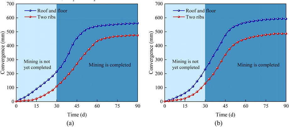
Figure 19. Surface displacement of the roadway after roof cutting blasting over time: (A) measuring station 1; (B) measuring station 2.
After the completion of deep-hole blasting roof cutting operations, the mining operation began. Due to the advance support stress induced by mining activity, the air return downhill started to deform, and at this point, the rate of surface displacement change was significant. After 30 days, the mining operation was completed, and the surface displacement rate began to decrease as the stress was redistributed in the working face. The roadway deformation stabilized approximately 40 days after the completion of the mining operation.
The maximum convergence measured at the two monitoring points was 457 mm and 486 mm for the two ribs, and 565 mm and 592 mm for the roof and floor, respectively.
The results indicate that after the deep-hole blasting roof cutting measures were implemented at the stop line of the Ji-17-21080 working face, effective control was achieved over the deformation of the air return downhill. Although some deformation occurred, the deformation remained within manageable limits. With appropriate maintenance and reinforcement measures, the roadway can be used for the next working face, achieving the intended objectives.
This study focused on the Ji-17-21080 working face at Pingdingshan No. 2 Mine. The principle of deep-hole blasting roof cutting technology for the working face was studied. The conclusions are as follows:
(1) By analyzing and comparing the structural characteristics of the main roof layer near the stop line, the principle of deep-hole blasting roof cutting to protect the main roadway in the mining area was clarified. On one hand, cutting the roof behind the stop line changes the structure of the main roof layer, reducing the transmission of stress from the goaf. On the other hand, forming a blast-induced weakening zone within the stop-mining coal pillar reduces the size and range of the advance support stress.
(2) FLAC3D was used to compare the stability of the main roadway under four scenarios. In Cases 1–4, the maximum deformation of air return downhill was 482 mm, 1,002 mm, 779 mm, and 515 mm, respectively. The simulation results show that the roof cutting measures play a crucial role in slowing down the transmission of mining-induced stress and optimizing the stress environment. Moreover, the effectiveness of two roof cutting lines was superior to a single roof cutting line.
(3) A deep-hole blasting roof cutting plan was designed for the Ji-17-21080 working face, with the first roof cutting line placed 10 m behind the stop line and the second placed 20 m ahead of the air return downhill. Field monitoring results show that while the air return downhill exhibited some deformation, the roadway deformation remained within controllable limits, ensuring its suitability for normal operation.
While this study provides valuable insights into the application of deep-hole blasting roof cutting technology for pressure relief in the final mining phase, several areas warrant further investigation. Future research could explore the optimal placement and spacing of roof cutting lines to maximize stress relief and minimize roadway deformation. Additionally, studying the long-term stability of the main roadway after the implementation of roof cutting measures would provide a more comprehensive understanding of the technology’s effectiveness. Furthermore, the impact of different blasting parameters, such as hole diameter, depth, and explosive type, on the effectiveness of roof cutting should be investigated. Finally, a comparative analysis of deep-hole blasting roof cutting with other stress relief techniques could offer insights into the relative advantages and disadvantages of each method in various mining conditions.
The original contributions presented in the study are included in the article/supplementary material, further inquiries can be directed to the corresponding author.
BL: Writing–original draft, Conceptualization. DC: Investigation, Writing–original draft. CX: Software, Writing–original draft.
The author(s) declare that financial support was received for the research, authorship, and/or publication of this article. This research was financially supported by National Key Research and Development Program of China (2023YFC2907600), Postgraduate Research & Practice Innovation Program of Jiangsu Province (KYCX24_2852), Graduate Innovation Program of China University of Mining and Technology (2024WLKXJ018).
Author BL was employed by China PingMei ShenMa Group.
The remaining authors declare that the research was conducted in the absence of any commercial or financial relationships that could be construed as a potential conflict of interest.
The reviewer CM declared a shared affiliation with the authors to the handling editor at time of review.
The author(s) declare that no Generative AI was used in the creation of this manuscript.
All claims expressed in this article are solely those of the authors and do not necessarily represent those of their affiliated organizations, or those of the publisher, the editors and the reviewers. Any product that may be evaluated in this article, or claim that may be made by its manufacturer, is not guaranteed or endorsed by the publisher.
Bednarek, Ł., Małkowski, P., Niedbalski, Z., and Mucha, K. (2024). Steel arch and rock bolt support in terms of the Gateroad stability maintaining behind the longwall face. Appl. Sci. 14, 3594. doi:10.3390/app14093594
Cao, X. F., Wang, S., Wang, X. L., Lei, P. B., and Chen, W. F. (2024). Non-pillar mining of upper coal seam layers with double-roadway driving using a flexible-formwork pre-cast partition wall. Meas. Sci. Technol. 35, 105601. doi:10.1088/1361-6501/ad6027
Chen, D., Wang, X., Bai, J., Lu, J., Wu, B., Li, X., et al. (2024a). Advanced detection methods for tunnels and roadways: a review. Meas. Sci. Technol. 36, 012007. doi:10.1088/1361-6501/ad98b2
Chen, D. C., Wang, X. Y., Bai, J. B., and Li, M. L. (2024b). Characteristics of waterproof failure and optimal width of narrow coal pillars under the coupled effects of mining, excavation and seepage. Geomechanics Geophys. Geo-Energy Geo-Resources 10, 100. doi:10.1007/s40948-024-00825-2
Chen, D. C., Wang, X. Y., Bai, J. B., and Zhang, F. T. (2024c). Deformation mechanism and control technology of gob-side roadway with continuous mining and continuous backfilling: a case study. Geomatics Nat. Hazards & Risk 15, 30. doi:10.1080/19475705.2024.2350480
Chen, D. C., Wang, X. Y., Wu, S., Zhang, F. T., Fan, Z. Z., Wang, X. D., et al. (2023). Study on stability mechanism and control techniques of surrounding rock in gob-side entry retaining with flexible formwork concrete wall. J. Central South Univ. 30, 2966–2982. doi:10.1007/s11771-023-5436-z
Chen, D. C., Wang, X. Y., Zhang, F. T., Bai, J. B., Zhao, X. Q., Li, M. L., et al. (2024d). Study on the mechanism of progressive instability of special-shaped coal pillar and the stability control of roadway under the influence of mining. Rock Mech. Rock Eng. 57, 6461–6483. doi:10.1007/s00603-024-03798-6
Chen, X., Wang, S. B., Liu, H. G., Yang, J. H., Liu, S. Y., and Wang, W. B. (2022). Coal gangue recognition using multichannel auditory spectrogram of hydraulic support sound in convolutional neural network. Meas. Sci. Technol. 33, 015107. doi:10.1088/1361-6501/ac3709
Fu, Q., Yang, J., Gao, Y., Li, C., Song, H., Liu, Y., et al. (2024). Combined blasting for protection of gob-side roadway with thick and hard roof. J. ROCK Mech. GEOTECHNICAL Eng. 16, 3165–3180. doi:10.1016/j.jrmge.2023.11.027
Hu, C., Yang, X., Li, Q., Hu, B., Li, Y., Jiang, Q., et al. (2024). Key parameters of gob-side entry retaining by roof cutting in close-distance seam group. GEOMECHANICS Geophys. GEO-ENERGY GEO-RESOURCES 10, 55. doi:10.1007/s40948-024-00772-y
Huang, B., Liu, J., and Zhang, Q. (2018a). The reasonable breaking location of overhanging hard roof for directional hydraulic fracturing to control strong strata behaviors of gob-side entry. Int. J. Rock Mech. Min. Sci. 103, 1–11. doi:10.1016/j.ijrmms.2018.01.013
Huang, B. X., Cheng, Q. Y., Zhao, X. L., Xue, W. C., and Scoble, M. (2018b). Using hydraulic fracturing to control caving of the hanging roof during the initial mining stages in a longwall coal mine: a case study. Arabian J. Geosciences 11, 603. doi:10.1007/s12517-018-3969-5
Jaiswal, M., Sebastian, R., and Mulaveesala, R. (2024). Detecting meso-damage and subsurface cracks in a hard rock using frequency-modulated thermal wave imaging (FMTWI). Meas. Sci. Technol. 35, 035403. doi:10.1088/1361-6501/ad11c8
Kang, H., Gao, F., Xu, G., and Ren, H. (2023). Mechanical behaviors of coal measures and ground control technologies for China's deep coal mines – a review. J. ROCK Mech. GEOTECHNICAL Eng. 15, 37–65. doi:10.1016/j.jrmge.2022.11.004
Khademian, Z., and Sears, M. (2024). Contribution of individual support components to roof stability in a longwall gateroad. Min. Metallurgy & Explor. 41, 695–705. doi:10.1007/s42461-024-00925-3
Klishin, V. I., Fryanov, V. N., Pavlova, L. D., and Opruk, G. Y. (2019). Modeling top coal disintegration in thick seams in longwall top coal caving. J. Min. Sci. 55, 247–256. doi:10.1134/s1062739119025527
Li, G., Zhu, C., He, M. C., Zuo, Y. J., Gong, F. Q., Xue, Y. G., et al. (2023). Intelligent method for parameters optimization of cable in soft rock tunnel base on longitudinal wave velocity. Tunn. Undergr. Space Technol. 133, 104905. doi:10.1016/j.tust.2022.104905
Li, L., Yang, Y., Wu, L., Zhang, W., Yang, W., and Zhai, Y. (2024a). The entry retained along gob side with small coal pillar and its surrounding rock control: a case study. Sci. Rep. 14, 28081. doi:10.1038/s41598-024-77158-3
Li, Q., Wang, Z., Liu, N., Zhang, H., and Li, Z. (2024b). Research on process parameter optimization of irregular coal face. Sci. Rep. 14, 12086. doi:10.1038/s41598-024-62517-x
Liu, B., Yu, A. Z., Gao, K. L., Tan, X., Sun, Y. F., and Yu, X. C. (2022a). DSS-TRM: deep spatial-spectral transformer for hyperspectral image classification. Eur. J. Remote Sens. 55, 103–114. doi:10.1080/22797254.2021.2023910
Liu, X., Mei, G., Xie, X., Wang, S., and He, M. (2022b). Research and application of integrated presplitting blasting in nonpillar mining technology. SHOCK Vib. 2022, 1–15. doi:10.1155/2022/6637580
Liu, Z. C., Wu, W. M., Li, J. Z., Zheng, C. L., and Wang, G. F. (2024). Data-driven dynamic inclination angle estimation of monorail crane under complex road conditions. Meas. Sci. Technol. 35, 116117. doi:10.1088/1361-6501/ad662a
Lyu, J., Qi, L., Wang, X., Peng, Y., Han, W., and Li, S. (2023). Analysis of the impact of the combined use of rebar bolts and FRP bolts in the roadway enclosure. Sci. Rep. 13, 19630. doi:10.1038/s41598-023-46432-1
Ma, B., Tai, Y., Li, Y., Xia, H., and Meng, X. (2023). Investigation of the process of perforating hard roof in an innovative technology of directional roof-cutting by composite blasting. Energy Sci. & Eng. 11, 2585–2600. doi:10.1002/ese3.1475
Ma, X., He, M., Sun, J., Wang, H., Liu, X., and Zhen, E. (2018). Neural network of roof cutting blasting parameters based on mines with different roof conditions. Energies 11, 3468. doi:10.3390/en11123468
Shen, F., Song, Y., Zhao, W., Zhao, S., Yang, J., Tian, Y., et al. (2023). Research on novel method of gob-side entry retaining under the synergistic effect of roof cutting and roadside filling in thick coal seams. Rock Mech. Rock Eng. 56, 7217–7236. doi:10.1007/s00603-023-03385-1
Sun, X., Jin, T., Li, J., Xie, J., Li, C., and Li, X. (2023). Dynamic characteristics and crack evolution laws of coal and rock under split Hopkinson pressure bar impact loading. Meas. Sci. Technol. 34, 075601. doi:10.1088/1361-6501/acca3b
Sun, Y. T., Bi, R. Y., Chang, Q. L., Taherdangkoo, R., Zhang, J. F., Sun, J. B., et al. (2021). Stability analysis of roadway groups under multi-mining disturbances. Appl. Sciences-Basel 11, 7953. doi:10.3390/app11177953
Tu, M., Zhao, G., Zhang, X., Bu, Q., and Dang, J. (2022). Fracture evolution between blasting roof cutting holes in a mining stress environment. Minerals 12, 418. doi:10.3390/min12040418
Vatandoust, M., Saein, A. F., and Tanzadeh, P. (2023). How a basement fault has controlled Pb- Zn ore deposition within the Zagros Fold-Thrust Belt? a focus on remote sensing approaches. Eur. J. Remote Sens. 56, 23. doi:10.1080/22797254.2023.2166875
Wang, H. Y., and Miao, F. (2022). Building extraction from remote sensing images using deep residual U-Net. Eur. J. Remote Sens. 55, 71–85. doi:10.1080/22797254.2021.2018944
Wang, P., Zhang, N., Kan, J., Wei, Q., Xie, Z., Li, A., et al. (2024). Accumulated damage failure mechanism of anchoring structures under cyclic impact disturbance. Int. J. Min. Sci. Technol. 34 (12), 1693–1709. doi:10.1016/j.ijmst.2024.11.006
Wang, M., Zheng, H., Ma, Z., Mu, H., and Feng, X. (2023). Control technology of roof-cutting and pressure relief for roadway excavation with strong mining small coal pillar. SUSTAINABILITY 15, 2046. doi:10.3390/su15032046
Wu, W. D., Wang, T. C., Bai, J. B., Liu, J. H., Wang, X. Y., Xu, H. Y., et al. (2024). Failure characteristics and cooperative control strategies for gob-side entry driving near an advancing working face: a case study. Processes 12, 1398. doi:10.3390/pr12071398
Xie, S., Wu, Y., Guo, F., Zou, H., Chen, D., Zhang, X., et al. (2022a). Application of pre-splitting and roof-cutting control technology in coal mining: a review of technology. Energies 15, 6489. doi:10.3390/en15176489
Xie, S. R., Wu, Y. Y., Ma, X., Chen, D. D., Guo, F. F., Jiang, Z. S., et al. (2022b). Reasonable stopping method and retracement channel support at fully mechanized top coal caving working face of 15 m extra-thick coal seam: a case study. Energy Sci. & Eng. 10, 4336–4357. doi:10.1002/ese3.1301
Xu, X., Zhou, Y., Yang, J., Gao, Y., Zhu, C., Wang, Y., et al. (2024). An innovative mechanism of directional rock cracking mechanics and mine pressure control method for energy-gathering blasting. Rock Mech. Rock Eng. 57, 8657–8677. doi:10.1007/s00603-024-03998-0
Yang, J. X., Liu, J. F., Li, W. F., Dai, J. J., Xue, F. J., and Zhuang, X. Y. (2024). A multiscale poroelastic damage model for fracturing in permeable rocks. Int. J. Rock Mech. Min. Sci. 175, 105676. doi:10.1016/j.ijrmms.2024.105676
Yang, S., Li, G. C., Bi, R. Y., Yao, B. C., Feng, R. G., and Sun, Y. T. (2021). The stability of roadway groups under rheology coupling mining disturbance. Sustainability 13, 12300. doi:10.3390/su132112300
Yang, X. J., Hu, C. W., He, M. C., Wang, H. H., Zhou, Y. B., Liu, X. Y., et al. (2019). Study on presplitting blasting the roof strata of adjacent roadway to control roadway deformation. Shock Vib. 16. doi:10.1155/2019/3174898
Yetkin, M. E., Ozfirat, M. K., and Onargan, T. (2024). Examining the optimum panel pillar dimension in longwall mining considering stress distribution. Sci. Rep. 14, 6928. doi:10.1038/s41598-024-57579-w
Zhang, Q., Liu, J. M., Gu, J. Y., and Tian, Y. (2022). Study on coal-rock interface characteristics change law and recognition based on active thermal excitation. Eur. J. Remote Sens. 55, 35–45. doi:10.1080/22797254.2022.2031307
Zhang, X., Hu, J., Xue, H., Mao, W., Gao, Y., Yang, J., et al. (2020). Innovative approach based on roof cutting by energy-gathering blasting for protecting roadways in coal mines. Tunn. Undergr. Space Technol. 99, 103387. doi:10.1016/j.tust.2020.103387
Zhang, W., Ma, Q., Liu, X., Wang, E., Xie, W., and Song, D. (2024). Study on crack propagation mechanism and acoustic-thermal sensitivity analysis of pre-cracked weakly cemented rock [J]. Theor. Appl. Fract. Mech. 133. doi:10.1016/j.tafmec.2024.104619
Zhang, Y. Q., Wang, X. Y., Zhang, F. T., Li, M. L., Wang, G. H., Chen, D. C., et al. (2023). Retracement ground pressure appearance and control of the working face under the overlying residual pillar: a case study. Energies 16, 1701. doi:10.3390/en16041701
Zhu, H., and Wang, H. (2023). Case study on pre-splitting blasting reasonable parameters of goaf-side entry retained by roof cutting for hard main roof. Processes 11, 350. doi:10.3390/pr11020350
Keywords: main roadway, roof cutting, shaped charge blasting, hard roof, support stress
Citation: Liu B, Chen D and Xu C (2025) Deep-hole blasting roof cutting technology for pressure relief in the final mining phase of the working face: a case study. Front. Earth Sci. 13:1566968. doi: 10.3389/feart.2025.1566968
Received: 26 January 2025; Accepted: 26 February 2025;
Published: 19 March 2025.
Edited by:
Manoj Khandelwal, Federation University Australia, AustraliaReviewed by:
Wei Zhang, Liaocheng University, ChinaCopyright © 2025 Liu, Chen and Xu. This is an open-access article distributed under the terms of the Creative Commons Attribution License (CC BY). The use, distribution or reproduction in other forums is permitted, provided the original author(s) and the copyright owner(s) are credited and that the original publication in this journal is cited, in accordance with accepted academic practice. No use, distribution or reproduction is permitted which does not comply with these terms.
*Correspondence: Dingchao Chen, dGIyMzAyMDAwMmE0MWxkQGN1bXQuZWR1LmNu
Disclaimer: All claims expressed in this article are solely those of the authors and do not necessarily represent those of their affiliated organizations, or those of the publisher, the editors and the reviewers. Any product that may be evaluated in this article or claim that may be made by its manufacturer is not guaranteed or endorsed by the publisher.
Research integrity at Frontiers
Learn more about the work of our research integrity team to safeguard the quality of each article we publish.