 Huangbin Jiang1,2
 Chu Jiang
94% of researchers rate our articles as excellent or good
Learn more about the work of our research integrity team to safeguard the quality of each article we publish.
Find out more
ORIGINAL RESEARCH article
Front. Earth Sci., 21 February 2025
Sec. Geohazards and Georisks
Volume 13 - 2025 | https://doi.org/10.3389/feart.2025.1559663
This article is part of the Research TopicEvolution Mechanism and Prevention Technology of Karst Geological Engineering DisastersView all 8 articles
The water gushing disaster in karst unfavorable geology has always been one of the difficult problems to be solved in the engineering field. In view of engineering problems such as water gushing in karst geology with relatively high-water flow velocity and water seepage at the joints of the underground diaphragm wall which is concealed, a treatment method for water gushing disasters in karst geology based on physical detection combined with grouting is proposed. The main steps of this method are as follows: Firstly, according to the analysis results of engineering geological investigations, by selecting appropriate physical detection means, accurately locate the hidden danger positions such as underground water gushing channels and cracks. Then, based on the results of physical detection, select appropriate grouting materials and techniques to conduct water blocking treatment at the water gushing points and effectively block the water gushing paths. In addition, the feasibility of the above method has also been verified through engineering applications. For the water gushing problem in the limestone area with extensive karst development, the electrical method of geophysical exploration technology was adopted to clarify the karst water gushing channels. And combined with the clay-cement paste grouting blocking technology to block them. The results show that the water blocking effect is obvious, and the water gushing volume has been drastically reduced from 103,900 to 8,600 m³/d, with a reduction rate as high as 91.72%. Moreover, for the concealed water gushing disasters at the joints of the underground diaphragm wall, the sonar detection method was selected to explore the positions of water gushing. Then the cement-water glass double-liquid grouting method was used to conduct anti-seepage treatment at the water gushing positions. An inspection of the water gushing situation after treatment found that the leakage phenomenon at the joints was significantly reduced. The research results can provide certain references for the design of treatment schemes for similar water gushing disasters in karst unfavorable geology.
Karst geology is mainly composed of caves and fissures, which have the characteristics of high-water content in fissures, high rock permeability, and easy collapse (Zhang et al., 2017). Along with unpredictable groundwater flow, these special geological forms and hydrological conditions bring many hidden dangers to the production and construction of karst areas, especially in the process of underground construction, which is prone to water inrush disasters (Bai et al., 2022; Wang et al., 2017; Li et al., 2013; Lan et al., 2021), causing serious economic losses and casualties (Zhang et al., 2022). For example, in 2007, a major water leakage accident occurred in the Yesanguan Tunnel of the Yiwan Railway, resulting in 52 casualties. China has karst landforms that account for one-third of its total land area, making it one of the countries with the widest distribution of karst landforms in the world. When carrying out production and construction in provinces such as Yunnan, Sichuan, Hunan, and Guangxi in China, it is inevitable to deal with karst geological problems (Wang et al., 2022; Zhao et al., 2013; Qiu et al., 2023). Therefore, it is urgent to carry out research on the treatment methods for geological disasters caused by foundation pit water inflow in karst areas.
Currently, the treatment techniques for water inflow in karst areas mainly include methods such as foundation pit dewatering, grouting reinforcement, and anti-seepage treatment (Liu et al., 2022; Lu et al., 2013; Parise et al., 2008; Zhang et al., 2019). Foundation pit dewatering uses pumping equipment to lower the groundwater level, thereby reducing water inflow, and is commonly used for water level control in the initial stage. However, precipitation methods are often only temporary solutions and will have a certain impact on surrounding water resources (Liu et al., 2021; Peng et al., 2020; Wan et al., 2021). Grouting reinforcement technology, as the core means of preventing water inflow in karst areas, uses high-pressure grouting and other processes to seal the cracks and caves around the foundation pit, forming a strong waterproof barrier (Ma et al., 2022; Xu et al., 2021; Li et al., 2019). In recent years, new grouting materials and processes such as micro grouting and chemical grouting have gradually been applied, which can form effective sealing in finer cracks and significantly improve the anti-seepage effect (Liu et al., 2018; Gutiérrez et al., 2014; Liu et al., 2019). The anti-seepage technology further prevents water flow into the foundation pit area by setting up anti-seepage walls, geomembranes and other facilities, ensuring the stability of the foundation pit (Qiu et al., 2022; Li et al., 2024; Li X. F. et al., 2018).
The existing prevention and control technologies have to some extent solved the problem of water inflow, but due to the limitations of specific geological conditions on the application effects of various technical means, the most suitable systematic construction plan still needs to be selected according to the actual situation. For this reason, scholars at home and abroad have begun to conduct a series of systematic studies on the treatment of water inrush disasters under different geological conditions (Li S. C. et al., 2018; Song et al., 2021; Zheng et al., 2019). For example, Li et al. (2021) proposed a new type of pipeline water spraying geological disaster treatment technology and construction technology in karst areas, effectively solving the karst water inrush disasters in limestone mines; Yang et al. (2020) described the pre grouting reinforcement technology for underwater karst areas of Changsha Xiangjiang shield tunnel, which is a systematic grouting reinforcement technology for tunnel excavation in underwater karst areas; Cui et al. (2015) explored a geological hazard prevention measure for shield tunneling in karst geology and cave karst areas, and verified the applicability of the measure through on-site cases. There have been many achievements in the systematic treatment of water inrush disasters in karst areas, but due to the complexity of karst areas, there are many special geological landforms, and the above water inrush disaster engineering treatment schemes have poor adaptability to these special sections.
Based on the foregoing, this study proposes a treatment approach that combines physical detection and grouting techniques for water inrush disasters in underground engineering projects with diverse geological formations. Through practical engineering applications, the suitability and effectiveness of this method have been demonstrated, thereby establishing a foundation for similar engineering projects and contributing to the further enhancement and refinement of the treatment technologies and construction methodologies for water inrush disasters in underground engineering.
A limestone mine affiliated with a certain cement production company in Hunan, China, employs a depressed open-pit mining approach. This limestone mine occupies an area of 327,000 m2 and has a perimeter of 2,527 m, with a designed excavation depth of 100 m. Since 2016, a karst cave at the elevation of +27 m on the south pit wall has experienced a sudden water inrush (designated as water inrush point No. 1), and the daily water inrush volume has reached 20,000 m3. As the mining depth further extends, a water inrush occurs in a karst fracture at the +9-m platform (termed water inrush point No. 2), and the water inrush volume exhibits a steadily increasing tendency. By October 2018, the maximum water inrush volume has reached 103,900 m3/d. The actual scene photographs of the mine and the water inrush locations are presented in Figure 1. This geological disaster has consequently led to an increment of six million yuan in the monthly cement production cost.
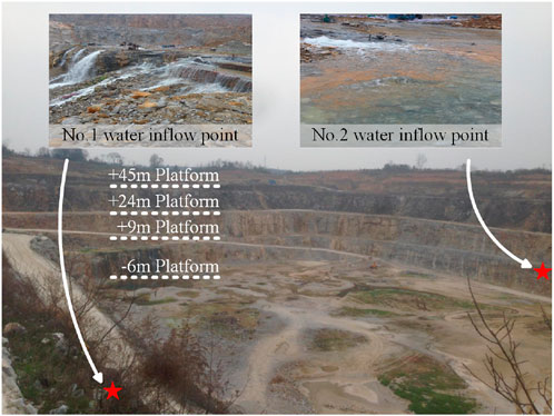
Figure 1. Realistic photos of mining areas and water inflow points.
A particular subway station in Guangxi, China, adopts a four-story underground double-column three-span structural design, with shield lifting shafts located at both the northern and southern ends. The depth of the foundation pit for the main structure of the station is 30.8 m, and that of the foundation pit at the enlarged end is 32 m. The construction method adopted is the cut-and-cover method. The foundation pit support system utilizes 1,200 mm diaphragm walls and an internal support structure to guarantee stability during the construction process. The construction site is illustrated in Figure 2. It is worth noting that the project is located in a karst developed area, and the surrounding high-rise buildings are close to the station foundation pit, with a horizontal distance of about 31.5 m between these buildings and the station foundation pit. Additionally, the bottom of the section of Line 1 is situated above the gravel layer and silty-fine sand layers. Hence, if water leakage occurs during the foundation pit construction process, it will exert a substantial impact on the surrounding buildings and the currently operating Line 1.
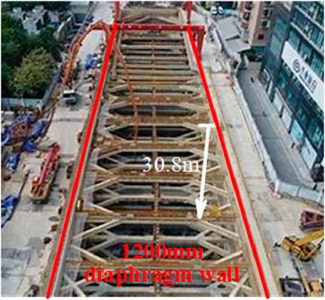
Figure 2. Construction site.
To begin with, preliminary investigation and analysis are of crucial importance to guarantee the safety of construction and the formulation of treatment measures. Subsequently, in order to ascertain the water inrush circumstances and define the grouting scope, it is requisite to pick out suitable and dependable physical exploration techniques from a variety of methods. Once the actual state of the water inrush is acquired, the coordinated grouting mode is implemented, with appropriate grouting standards, materials and processes being selected. Eventually, the efficacy of the method is verified by means of core drilling, unconfined compressive strength testing, and groundwater level monitoring. The specific procedure is illustrated in Figure 3.
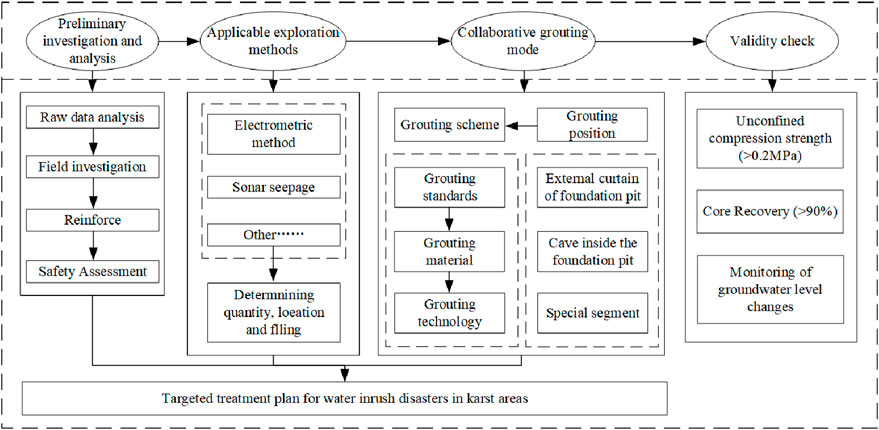
Figure 3. Technology flowchart.
To provide accurate data and a scientific basis for anti-water inflow measures in the construction of karst geological water inrush disasters, this study used electrical exploration instruments and three-dimensional velocity vector sonar measuring instruments as shown in Figures 4, 5 to detect geological information of limestone mining areas and seepage at the joints of diaphragm wall. Electrical exploration and sonar detection are commonly used comprehensive detection techniques for dealing with water inrush disasters in karst areas. Electrical exploration can be used to identify large-scale geological structures and geological disasters (such as karst caves, water-rich areas, fractured rock layers, aquifers, etc.). Sonar detection, by emitting sound waves and measuring echo signals, can accurately identify the direction, velocity, and flow changes of water flow, including revealing hidden leakage points that are difficult to detect by other methods.
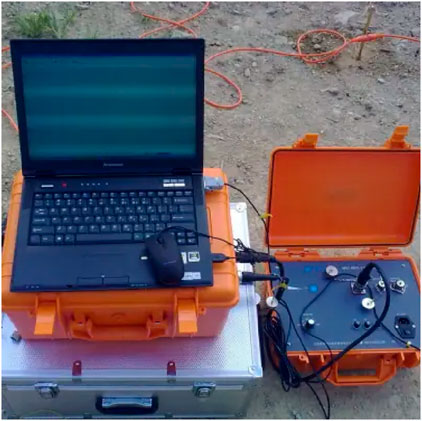
Figure 4. Electrical exploration instruments.
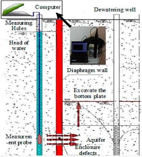
Figure 5. Schematic diagram of three-dimensional velocity vector sonar measuring instrument and detection principle.
Drilling operations should strictly follow China’s Code for Engineering Geological Drilling (DZ/T0017-1991). The error between the drilling azimuth and inclination during the drilling process should be controlled within 2°. After the installation of the grouting casing, cement slurry should be used for fixation, and a hydrostatic test should be conducted after solidification. The test pressure should reach 1.5 times or more than the final grouting design pressure. At the same time, detailed records should be kept of the number, specific location, and filing status of water inrush or cave recharge runoff zones in karst areas.
The grouting materials should be selected according to the specific engineering geological conditions. This article selects the following two commonly used low-cost and environmentally friendly underground water blocking and grouting materials.
The clay-cement paste slurry is applicable to grouting reinforcement projects in unfavorable geological conditions such as large karst caves, dissolution fractures, fracture zones and joint fracture development zones. Its physical properties like fluidity, setting time and flow time can be adjusted according to the actual situation, demonstrating strong adaptability. The grouting method of “from bottom to top with small-interval lifting” can be adopted for grouting, as specifically shown in Figure 6.
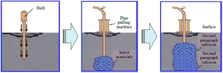
Figure 6. Construction schematic diagram of clay cement paste from bottom to top.
The cement-sodium silicate two-liquid grouting materials are composed of cement, sodium silicate and other admixtures. The mass ratio of water: cement: sodium silicate is generally 1.5: 1: 0.2. The types and dosages of admixtures can also be adjusted according to the actual grouting parameters required. The cement-sodium silicate two-liquid grouting materials are suitable for grouting anti-seepage projects in unfavorable geological conditions such as filled dissolution areas and narrow and long fractures. The grouting method of “sectional grouting from bottom to top, hole mouth sealing and circulation grouting inside the hole” should be adopted for grouting, as specifically shown in Figure 7.
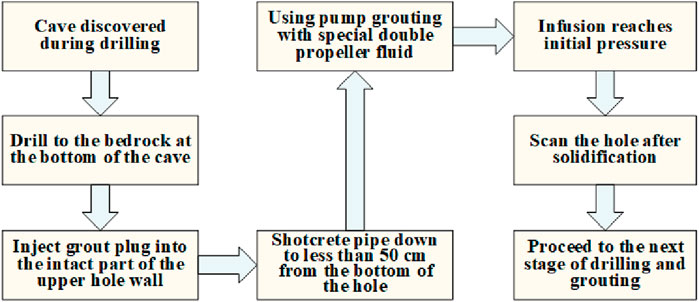
Figure 7. Double slurry construction process diagram.
For curtain grouting, the parameters mainly include the thickness of the curtain body (spacing, number of rows, pressure), the anti-seepage strength of the stone body and filling material (grout, pressure), etc. Specifically, the diffusion radius corresponding to different fracture magnitudes, and the length of the grouting section are presented in Table 1.
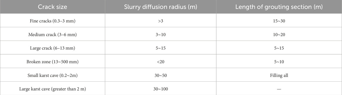
Table 1. Grouting parameters (Zhang et al., 2018).
When it comes to grouting unfilled karst caves, clay-cement paste slurry is employed for consolidation and filling purposes (see Figure 8). In the case of grouting fully filled and semi-filled karst caves, a relatively high grouting pressure should be applied to ensure that the clay-cement paste slurry can effect compacted filling of the fillings. Moreover, for karst caves with a diameter exceeding 0.5 m or relatively large dissolution fractures, due to the excessive absorption of grout, the treatment principle of “prior filling followed by compaction” ought to be adhered to. Use PVC sleeves with a diameter of 48 mm and a spacing of 4m for grouting, and complete a supplementary survey between the two grouting holes.
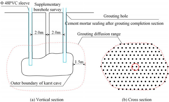
Figure 8. Schematic diagram of unfilled karst cave treatment.
When the velocity of the underground water flow is relatively high, the approach of constructing measure holes can be utilized for grouting. Initially, measure holes are added approximately 1.5 m beside the grouting holes, and the diameter of the drilled holes is expanded to 110–150 mm. Inert materials such as sand and gravel are first filled into the measure holes (as illustrated in Figure 9), and subsequently, low-slump paste slurry is injected. The grouting pipe is required to be a large-diameter one with a diameter of no less than 75 mm, and the rated pressure of the grouting pump should be no lower than 20 MPa.
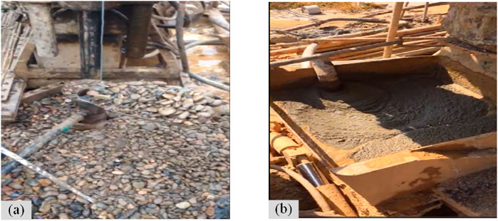
Figure 9. Measures for hole filling (A) filling sand and gravel material; (B) pouring cement mortar.
Upon the completion of karst grouting both inside and outside the foundation pit, reserved holes should be arranged at the joints of the underground diaphragm wall, with a hole spacing of 1 m, as depicted in Figure 10. When water inrush occurs in the upper overburden layer, the cement-sodium silicate two-liquid grouting materials can be used for anti-seepage and consolidation grouting.
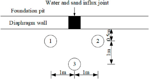
Figure 10. Layout of reserved grouting holes for the joints of the diaphragm wall.
To assess the effectiveness of curtain grouting, it is necessary to conduct a spot check on 10% of the total number of grouting holes, with the number of checked holes being not less than three. Samples should be obtained using the core drilling method in line with the Specification for Geological Core Drilling DZ/T 0227 - 2018. The core recovery rate is required to exceed 90%. Additionally, the unconfined compressive strength of the core samples taken 28 days after the karst cave treatment should be greater than 0.2 MPa.
According to existing hydrogeological data and field investigations of limestone mining areas, it is known that there is an ancient river channel within the working area, which is 3.5 km wide from east to west and 4 km long from north to south. The lower sand and gravel aquifer is in direct contact with the underlying carbonate rock, with strong hydraulic connections and abundant water content. At the same time, the mining area is covered with karst water, with a karst cave rate of 66% in boreholes and an average linear karst rate of 1.54%. Karst development is relatively extensive, with dense karst caves. Groundwater is closely connected to the hydraulic system of the bedrock layer, providing continuous replenishment for sudden water disasters.
To accurately obtain the geological structure information of the mining area, the geological exploration method was used to scan the mining area, and the joint surface structure map and resistivity scan map of the mining area were obtained. Due to space limitations, only geological information near South ZK-4 and South ZK-5 will be presented (see Figure 11). As shown in the figure, there are many steeply inclined conjugate torsional joints in the mining area, and multiple fault structures such as limestone layers are cut by horizontal structures. As shown in Figure 12, the summary of drilling information indicates that the mining area has formed strong structural dissolution in the south and northwest, including northeast trending compression torsional faults F1-1, F1-2, F1-3, and northwest-trending fault F2. Various karst channels and joint fissures are interconnected, and groundwater forms a strong runoff zone along the bedrock fissures and fault fracture zones in the south of the mining area. At the same time, it is discharged into the mine pit through the north, resulting in three water inflow points: South No.1, Southwest No.2, and North No.3 (later added).
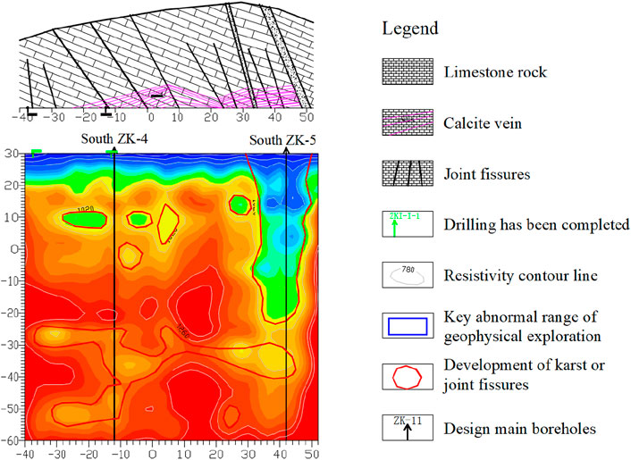
Figure 11. Geophysical exploration results of south ZK-4∼South ZK-5 drilling holes.
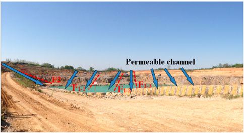
Figure 12. Schematic diagram of mine fault.
Based on precise geophysical information, the following combined grouting modes are adopted for the karst development section and nonkarst development section: the karst development section adopts a double row hole design with a hole spacing of 3 m and a row spacing of 2.5 m; Single row holes with a spacing of 3 m are used in nonkarst development sections; The drilling depth is 10 m below the karst floor. The selection of slurry materials is based on geological conditions, using clay composite slurry with a flowability of 110 mm and clay composite slurry with a flowability of 75 mm, ensuring good permeability and stability of the slurry. The grouting pressure is set at 0.8–3.5 MPa to ensure that the slurry can effectively penetrate and seal cracks and voids. In the grouting operation, low slump grout and pulsating grouting methods are used to ensure uniform injection of grout into karst voids and avoid uneven seepage. Slurry with higher fluidity can quickly cover and fill larger cracks and voids, while slurry with lower fluidity helps to form a stable sealing layer and enhance the reinforcement effect.
After the first phase of curtain grouting treatment (with a total of 334 grouting holes completed, curtain grouting footage of 34,272.9 m, and a total injection volume of 35,757 m3), the water inflow within the curtain line range in the southern part of the mine is about 5,000 m3/d, and the water inflow within the unexecuted curtain grouting range in the northern part is about 8,000 m3/d. The water inflow in the entire mine is about 13,000 m3/d, which is 87% lower than the initial water inflow disaster. But after the formation of the first curtain for a period of time, the total water inflow of the mine gradually increased again. The possible reason for this may be that water flows around the formed curtain body, causing seepage and water influx from the fault fracture zone or karst development zone in the north and northwest of the mine. Through the excavation of the F2 fault zone in the northwest by groundwater and the damage caused by blasting to certain parts of the original curtain body, the total water inflow of the mine gradually increases.
Based on the analysis of grouting conditions, the basic information such as the hole numbers of the main inlet channels has been sorted out as shown in Table 2. The boreholes in the table all show varying degrees of grout leakage at the water inflow points during grouting (see Figures 13, 14), suspected to be small fissure channels or small lava pipelines, which are the main permeable pathways outside the curtain line of the mine pit. The curtain line from K361# to K489# is about 387 m long, indicating that the leakage range and fissure distribution are mainly in this section, which should be the focus of treatment.
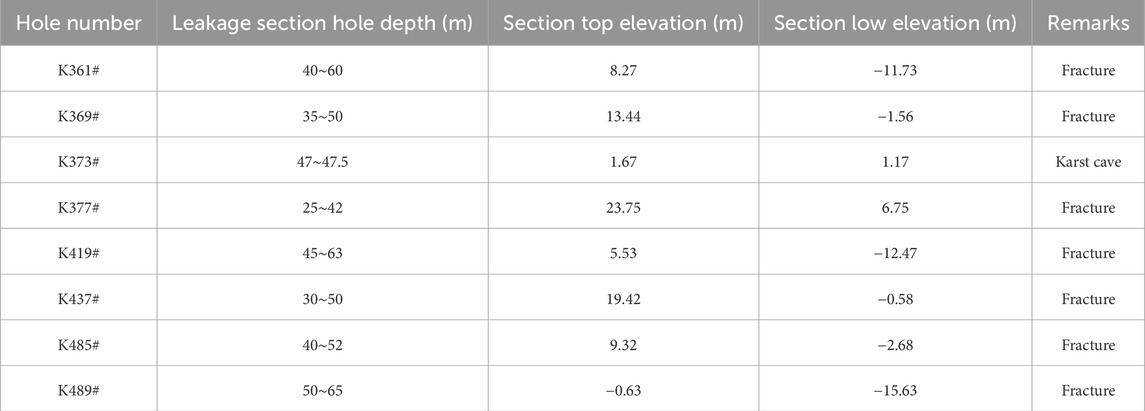
Table 2. Basic information of main inlet channels.
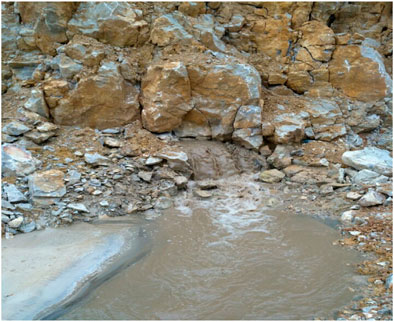
Figure 13. Photo of leakage at the water inflow point during K373# grouting.

Figure 14. Photo of leakage at the water inflow point during K485# grouting.
Therefore, the second phase grouting project mainly carries out curtain grouting treatment on the northern and western parts of the mining area (from 0 + 808 on the west side of the curtain line to 0 + 420 on the east side). Starting from the ZK270 hole in the last section of the first phase curtain, it overlaps parallel to the red line of the mining area to the original old mining area, forming a closed curtain anti-seepage body with the curtain of the first phase project and improving the overall stability of the curtain. The total length of the curtain line is 864 m, with a total of 299 grouting holes completed. The curtain grouting footage is 26,580.7 m, and the total injected grout volume is 10,544.89 m3.
After grouting, the single-point water pressure method is used for construction effect inspection, and the single-point water pressure test is carried out in accordance with Appendix A of DL/T5148-2012. The water pressure test of the inspection hole shows that the permeability value is basically less than 3 Lu, with an average permeability of 2.27 Lu, which meets the anti-seepage standard. Compared with the permeability value before grouting of the pilot hole, it has decreased by 72.0%, and the permeability of the rock mass has significantly decreased, indicating that the permeability conditions of the rock mass have been well improved after grouting treatment.
Figure 15 shows the comparison of the effects of grouting on the core sample after grouting and the treatment of water inflow in limestone mining areas before and after grouting construction. The slurry stone body extracted from hole J372 at 36.5 m–37.2 m showed good integrity, and the UCS and core recovery rate of the drilling samples met the requirements. After the sealing construction of key water inflow channels near WK133 and WK221 was completed, the water-blocking effect was significant, and the subsequent water inflow in the mine remained stable at 8600 m3/d. This combined grouting mode successfully addresses the complex geological conditions of limestone rock dissolution and effectively improves the waterproofing and reinforcement effect of foundation pits.
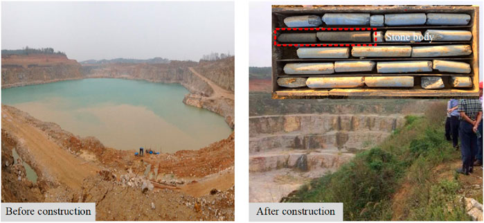
Figure 15. Comparison of the effect of core sample and limestone mining area water inflow treatment after grouting before and after grouting construction.
The sonar detection technology was adopted to detect the flow rate and velocity distribution of the seepage test holes, and the results are shown in Figure 16. It can be seen that the flow velocity of ZK1∼3 directly facing the joint is much higher than the infiltration flow velocity warning line (2 × 10⁻⁴ cm s−1), and the flow rate of ZK2 test hole has reached 381 cm3 s−1. Therefore, waterproofing construction should be carried out at the joint. Meanwhile, since the ZK1∼3 test holes are located in the round gravel layer and silty-fine sand layers. To ensure uniform slurry permeation in the gravel and silty-fine sand layers, the cement-sodium silicate two-liquid grouting material can be chosen for grouting.
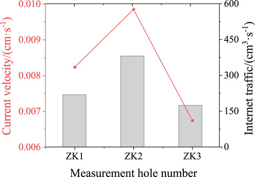
Figure 16. Flow velocity and flow distribution of sonar seepage detection test hole.
The water-cement ratio of the slurry is 1:1. The mixing ratio of the cement slurry to the mixed solution is 1:1. The mixed solution consists of a water reducing agent, an early strength agent and sodium silicate, and their mixing ratio is 4%: 6%: 90%. The dilution ratio of sodium silicate is 1:3. The sleeve valve pipe grouting process is adopted, and the grouting pressure is 0.3–0.5 MPa. During the foundation pit excavation process, trench excavation is carried out, and active protective water-stop steel plates are pasted at the joints (see Figure 17).
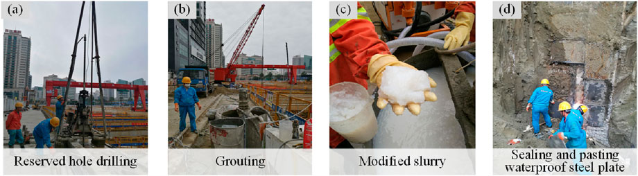
Figure 17. Grouting construction process for water inflow treatment of diaphragm wall joints. (A) Reserved hole drilling. (B) Grouting. (C) Modified slurry. (D) Sealing and pasting waterproof steel plate.
As shown in Figure 18, there are obvious signs of water seepage in the lower layer of the diaphragm wall joint before treatment. Long-term infiltration will erode the protective structure of the foundation pit and soften the rock and soil mass, seriously threatening the safety of subway station foundation pit construction. After processing, the water flow leakage phenomenon in the figure significantly decreased, and almost no water flow penetrated along the joint. A strong waterproof barrier has been formed by using grouting reinforcement and sealing materials at the joints. This indicates that through reasonable joint treatment measures, water seepage disasters can be effectively avoided, ensuring the safety of foundation pit construction.
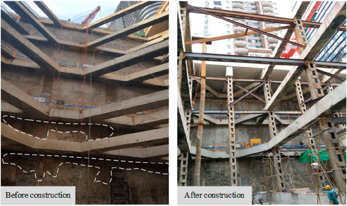
Figure 18. Construction effect of grouting treatment for water inflow at the joints of diaphragm walls.
The paper presents two water inrush scenarios in underground engineering, specifically water inrush in karst geology and water inrush at the joints of underground diaphragm walls. To address these two types of water inrush disasters, a method combining physical detection and grouting has been put forward for their remediation. Through practical engineering applications, the effectiveness of this method has been verified. The specific conclusions are as follows:
The electrical detection technique can clearly identify the distribution of underground karst caves and fractures. Precise curtain grouting is then carried out based on the results of physical detection. After grouting, the water inrush volume has dropped sharply from 103,900 m3/d to 8,600 m3/d, effectively controlling the water inrush disasters in karst geology.
The sonar detection technique can effectively detect the distribution of flow rate and velocity at the joints of underground diaphragm walls. Similarly, the cement-sodium silicate two-liquid grouting method, which has good grouting permeability, is employed for joint grouting, effectively controlling the seepage flow at these joints.
For different water inrush situations in underground engineering, appropriate physical detection methods can be selected to accurately locate the positions of water inrush, followed by grouting to block the water. It has been proven that this method is highly efficient.
The original contributions presented in the study are included in the article/supplementary material, further inquiries can be directed to the corresponding author.
HJ: Conceptualization, Methodology, Writing–original draft, Writing–review and editing. CJ: Conceptualization, Investigation, Methodology, Resources, Writing–original draft, Writing–review and editing. DC: Data curation, Writing–original draft. XQ: Data curation, Validation, Writing–original draft.
The author(s) declare that financial support was received for the research, authorship, and/or publication of this article. The research was supported by the Key R & D project of Hunan Province (2024AQ2044), the Natural Science Foundation Project of Hunan Province (2024JJ6282) and the Major projects of water conservancy science and technology in Hunan Province (XSKJ2023059-02, XSKJ2024064-2, XSKJ2024064-10, XSKJ2024064-9, XSKJ2024064-6).
The authors declare that the research was conducted in the absence of any commercial or financial relationships that could be construed as a potential conflict of interest.
The author(s) declare that no Generative AI was used in the creation of this manuscript.
All claims expressed in this article are solely those of the authors and do not necessarily represent those of their affiliated organizations, or those of the publisher, the editors and the reviewers. Any product that may be evaluated in this article, or claim that may be made by its manufacturer, is not guaranteed or endorsed by the publisher.
Bai, Y., Wu, Z., Huang, T., and Peng, D. (2022). A dynamic modeling approach to predict water inflow during karst tunnel excavation. Water 14, 2380. doi:10.3390/w14152380
Cui, Q., Wu, H. N., Shen, S. L., Xu, Y. S., and Ye, G. L. (2015). Chinese karst geology and measures to prevent geohazards during shield tunnelling in karst region with caves. Nat. Hazards 77, 129–152. doi:10.1007/s11069-014-1585-6
Gutiérrez, F., Parise, M., Waele, J. D., and Jourde, H. (2014). A review on natural and human-induced geohazards and impacts in karst. Earth Sci. Rev. 138, 61–88. doi:10.1016/j.earscirev.2014.08.002
Lan, X., Zhang, X., Yin, Z., Li, X., and Yang, T. (2021). Mitigation of karst tunnel water inrush during operation in seasonal variation zone: case study in nanshibi tunnel. Constr. Facil. 35, 4021010. doi:10.1061/(asce)cf.1943-5509.0001573
Li, J., Fu, H., Qiu, X., Wu, Y., and Chen, J. (2024). Research on dynamic response characteristics of red clay low embankment with different road structures under vehicle load. Transp. Geotech. 49, 101427. doi:10.1016/j.trgeo.2024.101427
Li, S., Gao, C., Zhou, Z., Li, L., Wang, M., Yuan, Y., et al. (2019). Analysis on the precursor information of water inrush in karst tunnels: a true triaxial model test study. Rock Mech. Rock Eng. 52, 373–384. doi:10.1007/s00603-018-1582-2
Li, S., Qi, Y., Li, Z., Li, H., and Zhang, J. (2021). A novel treatment method and construction technology of the pipeline gushing water geohazards in karst region. Tunn. Undergr. Space Technol. 113, 103939. doi:10.1016/j.tust.2021.103939
Li, S., Zhou, Z., Li, L., Xu, Z., Zhang, Q., and Shi, S. (2013). Risk assessment of water inrush in karst tunnels based on attribute synthetic evaluation system. Tunn. Undergr. Space Technol. 38, 50–58. doi:10.1016/j.tust.2013.05.001
Li, S. C., Xu, Z. H., Huang, X., Lin, P., Zhao, X. C., Zhang, Q. S., et al. (2018). Classification, geological identification, hazard mode and typical case studies of hazard-causing structures for water and mud inrush in tunnels. Chin. J. Rock Mech. Eng. 37, 1041–1069. doi:10.13722/j.cnki.jrme.2017.1332
Li, X. F., Sun, J. T., Chen, W. Z., Yuan, J. Q., Liu, J. Q., and Zhang, Q. Y. (2018). Strength and anti-washout property of fibre silica fume cement grout. Rock Soil Mech. 39, 3157–3164. doi:10.16285/j.rsm.2016.2844
Liu, J., Chen, W., Liu, T., Yu, J., Dong, J., and Nie, W. (2018). Effects of initial porosity and water pressure on seepage-erosion properties of water inrush in completely weathered granite. Geofluids 2018, 1–11. doi:10.1155/2018/4103645
Liu, J., Chen, W., Nie, W., Yuan, J., and Dong, J. (2019). Experimental research on the mass transfer and flow properties of water inrush in completely weathered granite under different particle size distributions. Rock Mech. Rock Eng. 52, 2141–2153. doi:10.1007/s00603-018-1719-3
Liu, J., Li, Z., Zhang, X., and Weng, X. (2021). Analysis of water and mud inrush in tunnel fault fracture zone—a case study of yonglian tunnel. Sustainability 13, 9585. doi:10.3390/su13179585
Liu, N., Pei, J., Cao, C., Liu, X., Huang, Y., and Mei, G. (2022). Geological investigation and treatment measures against water inrush hazard in karst tunnels: a case study in Guiyang, southwest China. Space Technol. 124, 104491. doi:10.1016/j.tust.2022.104491
Lu, Y. R., Liu, Q., and Zhang, F. E. (2013). Environmental characteristics of karst in China and their effect on engineering. Carbonates Evaporites 28, 251–258. doi:10.1007/s13146-013-0158-1
Ma, G. M., Zhang, X. L., and Yang, H. Q. (2022). Study on water inrush mechanism and safety critical conditions of karst tunnels. Saf. Environ. Eng. 29, 64–70. doi:10.13578/j.cnki.issn.1671-1556.20210786
Parise, M., Waele, J. D., and Gutierrez, F. (2008). Engineering and environmental problems in karst—an introduction. Eng. Geol. 99, 91–94. doi:10.1016/j.enggeo.2007.11.009
Peng, Y., Wu, L., Zuo, Q., Chen, C., and Hao, Y. (2020). Risk assessment of water inrush in tunnel through water-rich fault based on AHP-cloud model. Geomat. Nat. Hazards Risk 11, 301–317. doi:10.1080/19475705.2020.1722760
Qiu, X., Li, J., Jiang, H., Ou, J., and Ma, J. (2022). Evolution of the transient saturated zone and stability analysis of slopes under rainfall conditions. KSCE J. Civ. Eng. 26, 1618–1631. doi:10.1007/s12205-022-0733-x
Qiu, X., Li, J., and Zeng, B. (2023). Study on the wetting deformation characteristics of high liquid limit red clay under low stress conditions. Geotech. Mech. 44 (07), 2028–2040. doi:10.16285/j.rsm.2022.1222
Song, J., Chen, D. Y., Wang, J., Bi, Y. F., Liu, S., Zhong, G. Q., et al. (2021). Evolution pattern and matching mode of precursor information about water inrush in a karst tunnel. Water 13, 1579. doi:10.3390/w13111579
Wan, F., Xu, P., Zhang, P., Qu, H., and Wang, L. (2021). Quantitative inversion of water-inrush incidents in mountain tunnel beneath a karst pit. Adv. Civ. Eng. 2021, 9971944. doi:10.1155/2021/9971944
Wang, M., Yang, W., Zhou, Z., Li, L., Deng, D., and Zhou, Q. (2022). Research on the evolution mechanism of water inrush in karst tunnel and the safety thickness of water-resisting rock mass. Geotech. Geol. Eng. 40, 4539–4549. doi:10.1007/s10706-022-02169-8
Wang, Z. M., Rawal, K., Hu, L. B., Yang, R. D., and Yang, G. L. (2017). A study of dissolution and water-bearing characteristics of the restricted platform dolomite facies in the karst areas of Guizhou, China. China. Environ. Earth Sci. 76, 124. doi:10.1007/s12665-017-6419-x
Xu, Z., Lin, P., Xing, H., Pan, D., and Huang, X. (2021). Hydro-mechanical coupling response behaviors in tunnel subjected to a water-filled karst cave. Rock Mech. Rock Eng. 54, 3737–3756. doi:10.1007/s00603-021-02423-0
Yang, J., Zhang, C., Fu, J., Wang, S., Ou, X., and Xie, Y. (2020). Pre-grouting reinforcement of underwater karst area for shield tunneling passing through Xiangjiang River in Changsha, China. Tunn. Undergr. Space Technol. 100, 103380. doi:10.1016/j.tust.2020.103380
Zhang, C., Fu, J., Yang, J., Ou, X., Ye, X., and Zhang, Y. (2018). Formulation and performance of grouting materials for underwater shield tunnel construction in karst ground. Constr. Build. Mater 187, 327–338. doi:10.1016/j.conbuildmat.2018.07.054
Zhang, K., Zheng, W., Xu, C., and Chen, S. (2019). An improved extension system for assessing risk of water inrush in tunnels in carbonate karst terrain. KSCE J. Civ. Eng. 23, 2049–2064. doi:10.1007/s12205-019-0756-0
Zhang, L. K., Qin, X. Q., Tang, J. S., Liu, W., and Yang, H. (2017). Review of arsenic geochemical characteristics and its significance on arsenic pollution studies in karst groundwater, Southwest China. Appl. Geochem. 77, 80–88. doi:10.1016/j.apgeochem.2016.05.014
Zhang, W., Zhou, X., Wei, W., and Cheng, X. (2022). Risk assessment of water inrush in tunnels: a case study of a tunnel in guangdong province, China. Sustainability 14, 11443. doi:10.3390/su141811443
Zhao, Y., Li, P., and Tian, S. (2013). Prevention and treatment technologies of railway tunnel water inrush and mud gushing in China. Rock Mech. Geotech. Eng. 5, 468–477. doi:10.1016/j.jrmge.2013.07.009
Keywords: karst geology, water inrush disasters, physical detection, grouting, engineering application
Citation: Jiang H, Jiang C, Chen D and Qiu X (2025) Technology and application of treating water inrush disasters in underground engineering with the method of physical detection combined with grouting. Front. Earth Sci. 13:1559663. doi: 10.3389/feart.2025.1559663
Received: 13 January 2025; Accepted: 05 February 2025;
Published: 21 February 2025.
Edited by:
Tongming Qu, Hong Kong University of Science and Technology, Hong Kong SAR, ChinaCopyright © 2025 Jiang, Jiang, Chen and Qiu. This is an open-access article distributed under the terms of the Creative Commons Attribution License (CC BY). The use, distribution or reproduction in other forums is permitted, provided the original author(s) and the copyright owner(s) are credited and that the original publication in this journal is cited, in accordance with accepted academic practice. No use, distribution or reproduction is permitted which does not comply with these terms.
*Correspondence: Chu Jiang, ODI3MTczMDQ5QHFxLmNvbQ==
Disclaimer: All claims expressed in this article are solely those of the authors and do not necessarily represent those of their affiliated organizations, or those of the publisher, the editors and the reviewers. Any product that may be evaluated in this article or claim that may be made by its manufacturer is not guaranteed or endorsed by the publisher.
Research integrity at Frontiers
Learn more about the work of our research integrity team to safeguard the quality of each article we publish.