 Jian Lv1
 Tao Jiang
 Shenghua Cui
- 1State Key Laboratory of Geohazard Prevention and Geoenvironment Protection, Chengdu University of Technology, Chengdu, China
- 2Hydrogeological and Environmental Geological Survey Center, Geological Bureau, Urumqi, Xinjiang Uyghur Autonomous Region, China
Introduction: Vibration-induced densification of loose particle material is an important phenomenon in deformation and instability study of large spoil heap. To investigate the vibration-induced densification characteristics and deformation mechanisms of a low-density spoil heap under small seismic effects, a spoil heap located in western Sichuan Province was selected as the research subject, and a large-scale shaking table test was performed.
Methods: The settlement and acceleration response behaviors of the slope model during the vibration process were analyzed using three-dimensional point cloud data and acceleration time-history data, with horizontal and horizontal-vertical bi-directional seismic waves applied at progressively increasing amplitudes. Simultaneously, the natural frequency and damping characteristics of the slope model were determined using the transfer function. The deformation and damage modes, as well as the characteristics of vibration-induced densification, were also analyzed and discussed.
Results: The results indicate that vibration-induced densification of low-density spoil heaps under small seismic forces exists and becomes more pronounced with increasing excitation intensity. This vibration-induced densification leads to a progressively more significant elevation amplification effect.
Discussion: During the vibration-induced densification process, the medium undergoes self-organization in three phases, including settlement, dynamic equilibrium, and expansion. Based on the experimental observations, the deformation process of low-density spoil heaps can be divided into three stages: settlement and densification, collapse and disintegration, and downward misalignment and slippage. The findings of this study provide valuable insights and recommendations for the prevention and control of low-density spoil heap deformation in future engineering practices.
1 Introduction
The rapid economic development in the country has led to a continuous increase in various infrastructure projects. During the implementation of these projects, a significant amount of spoils is often generated. As these spoils gradually accumulate and have a loose structure, the stability of the excavated spoil heaps presents considerable challenges. The spoil heap, an artificially formed accumulation of loose material, necessitates specific compaction during both the design and filling stages. However, considering the variations in compaction during construction, the overall state of the spoil heap remains relatively loose, with significant voids and gaps between the particles. This results in characteristics of dispersibility, complexity, and susceptibility to deformation, which differ significantly from conventional soil and rock materials (Cui et al., 2020). Spoil heaps consist of a discontinuous aggregation of numerous individual particles, each of which is distinct and independent. Consequently, their stress and force transmission characteristics differ from those of conventional soil and rock materials, exhibiting unique propagation properties. Under seismic loading, the inertia forces generated by the earthquake cause displacements and relative movements between the particles. The interaction between larger particles reduces voids and facilitates the migration of finer particles to fill larger gaps, resulting in a significant densification (Liu C. Q et al., 2014; Chen et al., 2021) After seismic action, the deformation of spoil heaps is primarily controlled by two components: structure and particles (Xu, 2011). When the particle system is subjected to external forces, the structure deforms, while the particles themselves undergo compression and collision with one another. These interactions lead to changes in the system’s geometric configuration. Force transmission between particles is limited to contact interactions and is not constrained by the equations governing deformation compatibility (Chang et al., 2012). The internal force distribution within the discarded spoil exhibits significant spatial heterogeneity and characteristics of pressure expansion. Additionally, due to the dynamic properties of the particle medium, phenomena such as settlement, densification, and expansion can occur under seismic loading. Therefore, accurately assessing the response state of the spoil heaps during an earthquake is crucial for the design and monitoring of related spoil heaps. Currently, many scholars (Du et al., 2010; Sun et al., 2015; Wan et al., 2021; Ding, 2005) have conducted extensive experimental analyses on discontinuous assemblies such as loose accumulations and loess slopes, summarizing various seismic response patterns. However, research on the densification phenomenon during the vibration processes of large loose accumulations is relatively scarce (Gu et al., 2024). To achieve progress in understanding the characteristics and mechanisms of vibration-induced densification under seismic action, large-scale shaking table tests were used in this study. It is important for the design, stability evaluation, and safety mitigation of spoil heaps.
2 Study area
The spoil heap is located in the western part of Sichuan Province, an area prone to frequent earthquakes, with peak ground accelerations reaching up to 0.4 g (Figure 1).
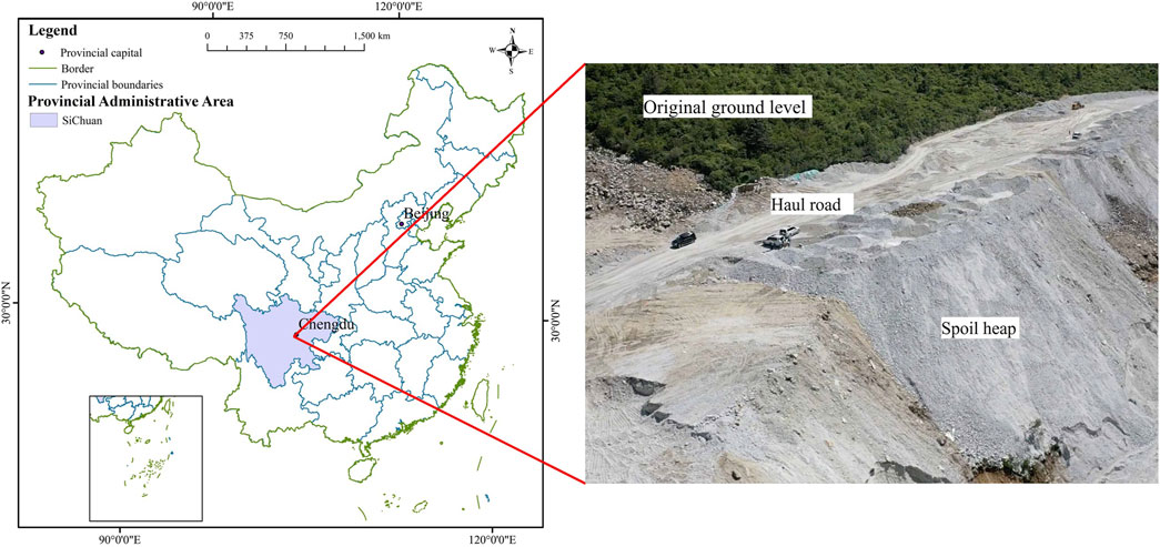
Figure 1. Study area and spoil heap.
The spoil heap in the study area, one of the largest along the entire railroad, making it an ideal test prototype for analysis, and the most hazardous profile within the study area was selected as the experimental prototype.
A partitioned, graded stacking method with a layered filling approach, as per the requirements was adopted at the spoil heap. Stacking begins at the toe wall position (Figure 1), considering the characteristics of the excavation material, construction organization, and topographic conditions. A haul road will be reserved at each platform level to meet construction needs.
The elevation range of the spoil heap along this profile is between 3,298 and 3,388 m, with a longitudinal length of 350 m and a natural slope gradient varies between 10° and 25°. The Quaternary substrate is predominantly composed of angular gravel, with an average thickness of 20 m and a maximum height of 73 m. A model of the spoil heap was developed using similarity calculations, with tests conducted at a 1:100 scale to construct a conceptual model (Figure 2).
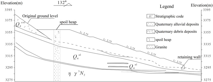
Figure 2. Engineering geologic profile of the spoil heap in the study area.
3 Methodology
3.1 Construction and instrumentation
The shaking table system is used for this experiment in the State Key Laboratory of Geological Disaster Prevention and Geological Environment Protection, Chengdu University of Technology (Figure 3). In addition, a 3D laser scanner (Reegl VZ-4000) was used to collect point cloud data during the test, and Cloud Compare (Liang et al., 2021) software was used to process the data. Cumulative settlement at each stage was represented by the distance difference between the point clouds under successive loading conditions. A 95% confidence band was applied to fit the scattered data more precisely, facilitating a clearer visualization of the model’s settlement trend.
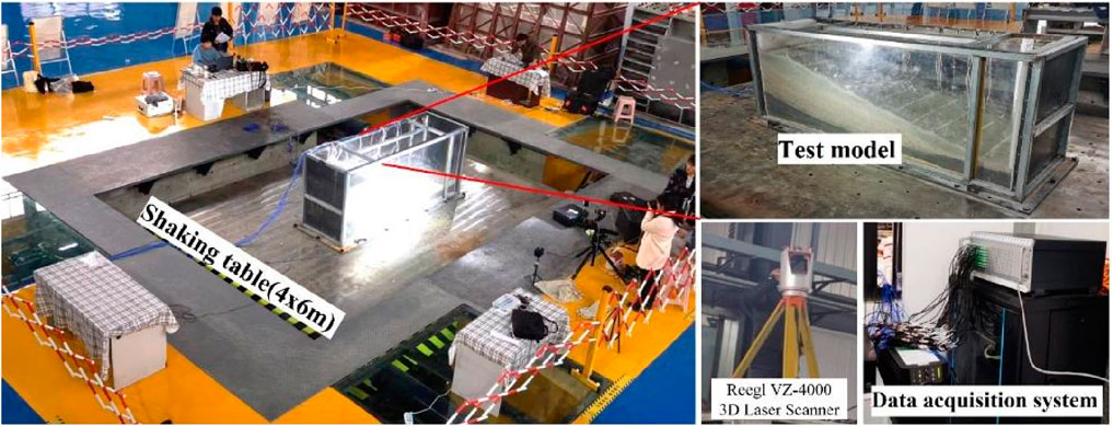
Figure 3. Laboratory vibration table experiment.
The table is 6.0 m in length and 4.0 m in width, with a frequency range of 0.1–60 Hz. The system can achieve maximum accelerations of ±1.5 g, ±1.2 g, and ±1.0 g, velocities of ±1.5 m/s, ±1.2 m/s, and ±1.0 m/s, and displacements of ±300 mm, ±250 mm, and ±150 mm in the X, Y, and Z directions, respectively. The system can apply both sinusoidal and real earthquake waves, meeting the experimental requirements.
The scaled model dimensions are 280 cm in length, 80 cm in width, and 120 cm in height. Tri-axial accelerometers are placed within the model. This sensor arrangement not only enables the monitoring of acceleration changes at critical locations, such as the shoulder of the slope, but also supports the collection of extensive data without disrupting the test.
To minimize experimental errors from boundary effects, sensors and monitoring equipment are positioned as centrally as possible within the model. Additionally, 8 cm thick foam boards were placed near the side panels of the model box to minimize boundary effects during the experiments. The layout of the slope model and measurement points is shown in Figure 4.
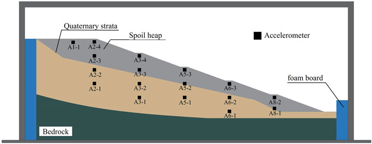
Figure 4. Slope model and measurement point arrangement.
3.2 Test materials
Based on the Buckingham π theorem and previous experiments (Ren, 2007; Yang et al., 2019; Gao et al., 2022) on physical similarity ratios, similarity indicators were selected, including model dimensions, density, elastic modulus, cohesion, internal friction angle, Poisson’s ratio, gravitational acceleration, stress, frequency, time, strain, and velocity (Table 1). This study aims to reveal the motion characteristics of the spoil heap, as the test is constrained by the site’s geological prototype and the size of the equipment. Therefore, density, modulus of elasticity, dimensions, and time are used as key indicators. The similarity ratios for the physical quantities tested are presented in Table 1.
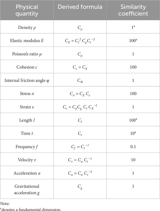
Table 1. Main similarity coefficients of the model.
In this study, controls the density of spoil heap is determined using similarity theory. To investigate the response characteristics of the spoil heap under seismic conditions at low compaction densities. Tests are conducted at a compaction density of 0.5, with primary control parameters kept constant. Selecting appropriate similar materials is crucial for the successful execution of the shaking table model tests. The range of suitable materials is broad, with selection principles that include stable physical and chemical properties, ease of parameter control, low cost, availability, and non-toxicity, as well as environmental friendliness. Most importantly, the physical and mechanical properties of the model must meet the similarity requirements. This experiment focuses on observing the movement of spoil heap particles during loading and simulating the failure and movement of the slope model, with the bedrock considered as an invariant layer. Figure 5 shows the particle size distribution curves for the spoil heap and the Quaternary cover layer in the study area. Material ratios are based on previous studies (Cui et al., 2019). The source of the material consists of two main components, one from fieldwork while the other from similar materials. The materials and their proportions for each layer are as follows, Spoil heap: Particles with a diameter of less than 1 mm are selected from the site for the model. Quaternary Layer: Particles with a diameter of less than 1 mm are selected from the on-site angular gravel soil for the Quaternary layer. Bedrock Model Material: The material ratios of similar materials based on previous studies (Huang, 2009), Barite powder: Quartz sand: Gypsum: Iron powder: Water: Glycerin = 37.5:37.5:7:18:11.48:2.3 (Table 2).
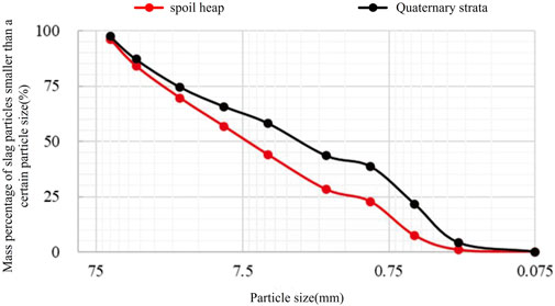
Figure 5. Grading curves of the spoil heap and the quaternary overburden in the study area.
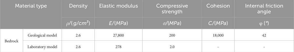
Table 2. Comparison of mechanical parameters of bedrock prototype and model materials.
3.3 Experimental program
To obtain the dynamic response characteristics and failure modes of the spoil heap, dynamic loading is applied using sinusoidal waves interspersed with natural waves (Figure 6). In addition to unidirectional X-axis vibrations, bidirectional composite vibrations in the Z and X directions are applied to simulate natural wave effects. Prior to localized deformation or overall failure, the maximum possible input wave loading is completed to gather sufficient vibration data for a comprehensive analysis of the model’s dynamic response. The loading sequence for input wave conditions is designed according to amplitude, frequency, and duration, progressing from low to high (Table 3), in line with the loading principles. Based on seismic case study analysis in the research area, the dominant frequency of earthquakes is typically below 20 Hz. Consequently, the input wave frequencies for this experiment are set at 6, 12, and 18 Hz, with subsequent loading frequencies increased to 30 Hz to induce model failure. The effective duration of each seismic loading is approximately 20 s, while the shaking table test input waves last about 18 s.
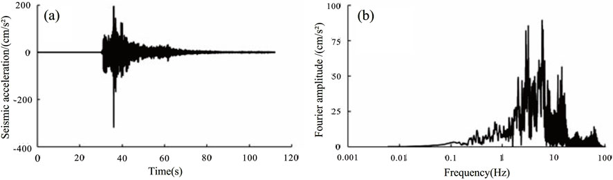
Figure 6. Natural wave acceleration spectrum and Fourier spectrum. (A) Natural wave acceleration spectrum (B) Fourier spectrum of natural waves.

Table 3. Shaker model test loading system.
4 Results
4.1 Settlement displacement
The collected point cloud data were processed to better understand the settlement process of the model during the experiment. Rectangular regions of point cloud data, where significant settlement was observed, were selected for analysis. These regions included the rear edge platform of the test model and the third and fourth stages.
The result of point cloud data processing is the change in displacement of the model surface under different conditions. Horizontal displacements of the model surface are inevitable during the vibration process, resulting in a slight accumulation, labeled as a positive displacement value. Additionally, label the vertical settlement displacements as negative displacement values. When the displacements in the observation area are predominantly negative, it indicates that the settlement of the model surface exceeds the accumulation, resulting in settlement deformation of the model.
To enhance clarity, the loading process was divided into three stages: early stage (0.1 g–0.35 g), middle stage (0.35 g–0.6 g), and late stage (0.6 g–1.0 g) (Table 4). Point cloud data from various loading stages were processed and compared using Cloud Compare software. During the early stage of vibration loading (Figures 7A), the model demonstrates typical settlement behavior under loading conditions 1–4, 4–7, and 7–10, with a maximum local settlement of 0.59 cm and an overall average settlement of 0.193 cm.
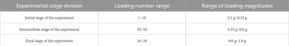
Table 4. Stages of the test process.
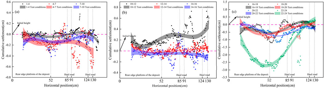
Figure 7. Cumulative settlement of the model during vibratory load loading plots. (A) Cumulative settlement of the model during the early stage of vibration loading. (B) Cumulative settlement of the model during the middle stage of vibration loading. (C) Cumulative settlement of the model during the late stage of vibration loading.
In the mid-stage of vibration loading (Figures 7B), significant accumulation and particle movement at the rear edge platform of the deposit were observed (loading conditions 10–12), with an average accumulation of 0.351 cm. Although particle movement of surface predominated during this stage, settlement also occurred under conditions 14–16, with an average settlement of 0.11 cm.
In the late stage of loading (Figures 7C), the model experienced noticeable deformation and failure, trending toward collapse, with the rear edge accumulating toward the front edge. During this phase, cumulative settlement primarily reflects the vertical displacement of the collapsed spoil heap rolling toward the front edge, with settlement characterized mainly by loss, reaching a maximum of 3.12 cm.
4.2 Accelerated response
Following the input of seismic waves, the acceleration response and patterns provide essential data for analyzing the model’s dynamic behavior. To facilitate analysis and accurately reflect the model’s response, Figure 8 shows the acceleration response time histories for the spoil heap model under loading conditions 3 (0.15 g), 6 (0.25 g), and 9 (0.35 g). The acceleration of the spoil heap model initially increases rapidly before stabilizing at the end of the vibration. The figure shows that the A8-2 monitoring point, located at the toe of the spoil heap model near the shaking table surface, displays an acceleration time history curve that closely matches the input excitation acceleration for the corresponding loading conditions. As elevation increases, the A2-4 monitoring point at the shoulder of the model shows a significant amplification of acceleration.
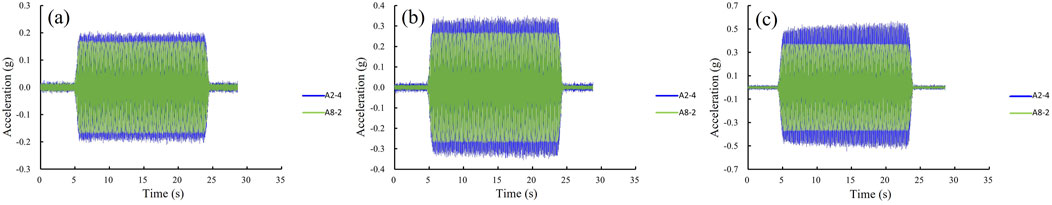
Figure 8. Acceleration time histograms for different loading conditions. (A) Monitoring points: A2-4, A8-2 (under working condition 3). (B) Monitoring points: A2-4, A8-2 (under working condition 6). (C) Monitoring points: A2-4, A8-2 (under working condition 9).
Figure 9 shows the displacement changes at the monitoring points during the early vibration phase (0.1 g–0.3 g), derived from the double integration of acceleration data. The downward vertical direction and the horizontal direction toward the front edge of the model are defined as positive displacements. Under dual-directional excitation (horizontal and vertical), a comparison of displacement amplitudes shows that the vertical deformation response is more pronounced during the early vibration phase.
Figure 9. Displacement at each monitory point. (A) point A1-1 at 0.1 g; (B) point A2-4 at 0.1 g; (C) point A3-4 at 0.1 g; (D) point A1-1 at 0.2 g; (E) point A2-4 at 0.2 g; (F) point A3-4 at 0.2 g; (G) point A1-1 at 0.3 g; (H) point A2-4 at 0.3 g; (I) point A3-4 at 0.3 g.
Figures 9B, D, F, G shows that throughout the early loading phase, vertical displacements are consistently greater than horizontal displacements, indicating that vertical movement predominates, with horizontal movement as a secondary response. Vertical displacements at the rear edge platform of the model remain relatively stable, suggesting a stronger vertical deformation response at this location. However, in Figures 9A, E, H, I, localized vertical displacements are observed to be negative and smaller than the horizontal displacements. Based on the particle ejection phenomenon described in previous studies (Liu H. X. et al., 2014), the accumulation and jump behavior observed at the rear edge of the spoil heap in this experiment may result from the model surface being at a free interface. Under the effects of elevation amplification and bidirectional excitation, many particles undergo translation and rolling at the surface, while a few experience collisions that generate vertical jumps. This leads to minimal displacement variations or no significant change in the model’s displacement.
4.3 Natural frequency and damping ratio
This section uses the MATLAB tfestimate function to analyze the evolution of the damping ratio and natural frequency of the model under seismic loading (Meng et al., 2021). To investigate the model’s settlement during the early loading stages, white noise frequency sweep results were calculated for loading conditions 1–4, 4−7, and 7–10, based on the spoil model’s measurement point layout (Figure 7). Figures 10A shows results with the A2-3 monitoring point as the excitation signal and the A2-4 monitoring point as the response signal. Figures 10B illustrates results with the A3-3 monitoring point as the excitation signal and the A3-4 monitoring point as the response signal.
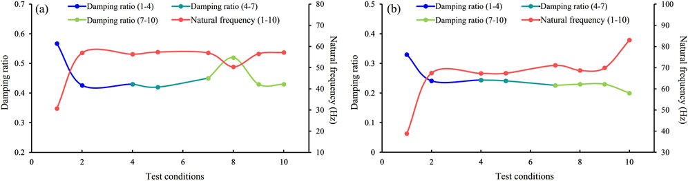
Figure 10. Variation of self-oscillation frequency and damping ratio of the test model. (A) Changes in the natural frequency and damping ratio at the rear slope shoulder (B) Changes in the natural frequency and damping ratio at the fourth-level haul road.
The settlement at the rear edge of the model during the early loading phase (0.1 g–0.35 g) is characterized by similar trends in natural frequency and damping ratio, as shown in the variation curves in Figure 10 for two different locations under loading condition 1–4. In Figures 10A, the natural frequency increases significantly by 83.4%, while the damping ratio decreases by 24.1%. In Figures 10B, the natural frequency increases by 73.3%, and the damping ratio decreases by 26%. The initial rise in natural frequency, followed by a decline, and the initial decrease in damping ratio, followed by an increase, suggest that this behavior results from the relatively low intensity of vibrations at the start. Upon loading initiation, the particle medium of the spoil heap is subjected to sudden external seismic forces, disrupting the supporting structures between particles and breaking the original equilibrium. The particle medium enters a temporary disordered state, and during subsequent vibrations, particles undergo motion and reorganization, transitioning from a loose, chaotic state to a stable, dense state, thereby enhancing the model’s stability under vibration. In loading condition 4–7, the natural frequency and damping ratio stabilize. In loading condition 7–10, a sudden change occurs at the rear edge platform, with natural frequency decreasing by 11.58% and damping ratio increasing by 15.5%. This change is hypothesized to result from the location reaching a balanced state after the previous loading conditions. Under additional vibrational loading, internal particles exhibit behaviors such as filling voids, arching, and self-organization, causing anomalies in the curves. The natural frequency and damping ratio at the fourth-level platform show upward and downward trends, respectively, similar to those in loading condition 1–4, with increases of 16.8% and decreases of 11.5%. This suggests that the region is undergoing further densification under vibration.
4.4 Deformation failure characteristics
Seismic waves were applied in a sequence from low to high amplitudes to observe the complete development of model deformation and failure. The test results show that the model remained relatively stable until the 0.6 g condition. However, once the sine wave acceleration amplitude reached 0.6 g, noticeable local deformation and damage were observed on the model. The complete process of deformation to failure of the model is shown in the following Figure. Before the acceleration amplitude reached 0.6 g, the model underwent overall vibrational settlement (Figures 12A), resulting in significant settlement relative to the original slope interface, while the surface morphology remained largely unchanged. When the acceleration amplitude increased to 0.6 g, clear rolling and jumping of particles on the model surface were observed, along with significant and persistent collapse. At this point, the surface morphology began to change, with pathways gradually disappearing and accumulation occurring at the front edge, transforming the surface into a flat inclined plane (Figures 12B). After reaching the 0.6 g condition, continued loading caused downward sliding, leading to complete collapse and failure of the model (Figures 12C).
5 Discussion
5.1 Deformation and failure modes
The analysis of acceleration, natural frequency, damping ratio, and damage phenomena in the results clearly demonstrates the impact of vibration-induced densification on the dynamic behavior of the spoil heap. This subsection will focus on the mechanism of vibration-induced densification.
Figure 10 shows that even under minor seismic activity, the vibration-induced densification phase of the model exhibits distinct characteristics. The densification phase can be divided into three stages, during the Self-Organized Settlement Phase, as seismic loading begins, particles transition rapidly from rest to motion, interlocking and filling voids under continuous external forces, which increases the model’s density. In the Self-Organized Dynamic Equilibrium Phase, the particles reach dynamic equilibrium, leading to overall model stability, where the seismic load no longer exceeds the threshold for internal failure. Finally, in the Self-Organized Expansion Phase, as seismic loading intensifies, it approaches the equilibrium threshold between particles. Continued loading disrupts this equilibrium, leading to deformation and structural failure. The three distinct phases of vibration-induced densification are shown in Figure 11. The stage of the particles within the spoil heap can be determined through in-situ soil density measurement tests conducted in the field. If the average of multiple measurements exceeds the initial density, the spoil heap is in the Self-Organized Dynamic Equilibrium Phase. Deformation in this phase helps maintain the stability of the spoil heap. If the measurement results are lower than the initial density, the spoil heap is in the Self-Organized Expansion Phase. Deformation in this phase accelerates the destruction of the spoil heap.
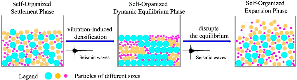
Figure 11. The evolution of vibration-induced deformation of low-density particle material.
The complete failure process of the model is described in Section 4.4, This section summarizes and analyzes the deformation and failure modes of the test model, based on experimental observations, the deformation and failure modes of the spoil heap with low-density under minor seismic conditions are categorized into three stages. Rear Settlement and vibration-induced densification Phase. A schematic of this phase is shown in Figures 12A. Under low-density conditions, numerous voids exist within the spoil heap, after continuous minor seismic vibrations, the model does not fail, and no accumulation occurs at the front edge. Seismic forces are thought to enhance the arching and void-filling effects among the particles, gradually filling larger voids. The particles self-organize, transitioning from a disordered to a more ordered state, resulting in closer contacts among particles. Surface Disintegration Phase. A schematic of this phase is shown in Figures 12B, after vibration-induced densification, the spoil heap gradually stabilizes. However, under stronger seismic loading and elevation amplification, the equilibrium between particles is disrupted, causing disintegration in stress concentration areas such as the crown and slope shoulder. Under excitation, some particles jump, eject, or accumulate, while most of the remaining particles continue to roll toward the front edge, gradually leveling the surface. Internal Sliding Phase, a schematic of this phase is shown in Figures 12C. In this stage, the structure of the spoil heap is completely destroyed, and the internal particles are out of equilibrium. Under the influence of seismic inertial forces and gravity, the spoil heap flows like sand, sliding downward and accumulating at the front edge.
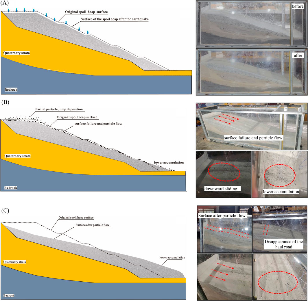
Figure 12. Deformation and Failure Modes. (A) Settlement at the rear slope and Compaction stage of the spoil mass. (B) Surface failure and disintegration stage of the spoil mass. (C) Downward sliding and misalignment stage of the spoil mass.
5.2 Self-organizing mechanism of particles in vibration-induced densification
In addition to the low-density model discussed, experiments were also conducted on a high-density model as a control group. The high-density model was constructed with a compaction level of 0.8, while all other conditions were identical to those of the low-density model. The amplification factor of peak ground acceleration (PGA) at any monitoring point is defined as the ratio of the peak acceleration response at that point to the peak acceleration at monitoring point A8-1. The elevation is measured from the bottom of the model as the vertical distance from each monitoring point to the reference plane. Figure 13 compares the PGA amplification factors of two models with identical experimental conditions but different compaction levels. Using Working Conditions 3 (0.15 g) and 6 (0.25 g) as examples, the model’s bottom serves as the reference plane. The figure shows the incremental changes in the PGA amplification factors at different elevations on the rear edge platform of both models. As the amplitude increases, the incremental PGA amplification factor at each point in the low-density model is consistently higher than that of the high-density model, with the largest difference reaching 4.5% and the smallest at 0.27%. Under the influence of initial minor seismic activity, the low-density model shows a progressively higher response due to the self-organizing densification effect (Liu Q. W et al., 2014).
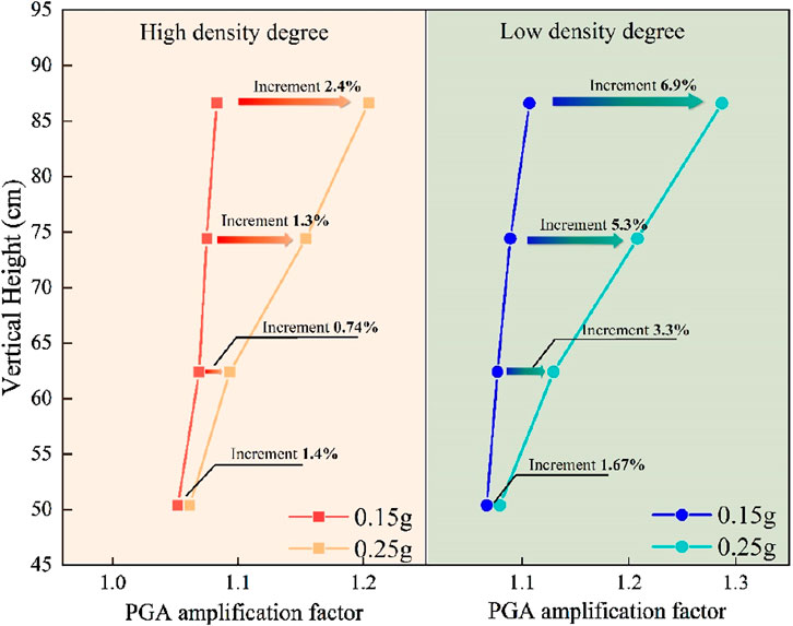
Figure 13. Comparison of PGA amplification factor increments for different compaction models.
Research on bulk materials typically uses spherical or cubic particles as ideal models for granular materials.
Previous studies (Peng et al., 2024) on non-cohesive cubic particle stacks have shown that force transmission occurs through random contact points. When particles are arranged symmetrically, the application of external loads is influenced by their arrangement, leading to both symmetrical and asymmetrical behaviors. After external loads are applied, asymmetrical force transmission causes a decrease in peak force displacement with increasing transmission distance, resulting in a parabolic transmission range. Force transmission between particles primarily occurs in two forms, including unidirectional and diffusive transmission (Figure 14). When particles are arranged asymmetrically, force transmission can cause uneven stress distribution. Asymmetrical conditions dominate in waste accumulation material, significantly increasing stress unevenness (Yang et al., 2021).
Figure 14. Schematic diagram of force transfer between particles. (A) Unidirectional transfer. (B) Diffusive transfer.
Under external loads, the granular medium and its particles deform, leading to relative displacements and self-organizing behavior (Li et al., 2024). The primary interaction forces between loose particles are shear resistance (friction and interlocking forces), which help maintain the stability of the granular material. When the forces on the particles exceed shear resistance, the granular material loses stability and undergoes movement-induced failure.
Vibrational loading introduces external forces that disrupt the original equilibrium, causing the particles to rearrange. Larger particles provide mutual stability and support, while smaller particles fill the gaps between them. This reduces porosity and increases density. These movements enhance the physical and mechanical properties of the material (Duan, 2010). Figure 15 shows the particle vibration-induced densification and force analysis (assuming ideal spherical particles) under seismic load F In the absence of boundary constraints on the slope, all particles are in motion. Taking particle D as an example, it experiences reaction forces from particles A and B, dynamic loads from particles F and G, and total shear resistance f from its neighbors. Although surrounded by other particles, D can maintain stability only through shear resistance. Once the external force exceeds D’s shear resistance, it will begin to move. In the spoil heap, particle D remains stable when the shear resistance exceeds the applied forces. Conversely, when shear resistance is lower than the applied forces, particle D becomes unstable, resulting in displacement and settlement. Similarly, the upper particles settle downward, causing the entire model to undergo settlement. At this point, the ratio of spoil heap settlement to lateral deformation is approximately 1:1. Previous studies (Gao, 2008) have shown that particle shape and roughness significantly influence inter-particle shear resistance. Greater particle deformation and roughness enhance shear resistance, thereby increasing stability.

Figure 15. Particle D force analysis.
5.3 Influencing factors of vibration-induced densification
Vibration-induced densification of granular materials is primarily driven by two factors, densification influenced by self-organization and particle packing, and external loads causing particle breakage (Golovanevskiy et al., 2011). As dynamic loads increase, densification intensifies while particle self-organization diminishes. Section 4.2 analyzes significant differences in the acceleration response of the model after vibration-induced densification at varying compaction levels. The second factor involves external loads generating compressive stresses greater than a particle’s crushing strength, causing breakage and subsequent settlement of the bulk material (Jia et al., 2011). When seismic activity affects spoil heaps, particles transition from a stable to a dynamic state, causing varying degrees of deformation. Research (Li et al., 2021; Wartman J. et al., 2005) shows that the relative motion between granular particles exhibits stick-slip behavior. External forces on the spoil heap material induce self-organized settlement, usually in localized regions. Particle movement must overcome shear resistance, transitioning from static to dynamic states instantaneously under shear stress, leading to stick-slip behavior. The periodic nature of stick-slip motion promotes self-organization within the particle pile. Stick-slip is the underlying cause of self-organization, with larger displacements and amplitudes indicating a stronger self-organization effect (Cengiz and Guler 2020).
6 Conclusion
This study, based on large-scale vibration table model tests of spoil heaps, reveals the phenomenon of particle vibration-induced densification in low-density spoil heaps under minor seismic conditions. The spoil heap undergoes vibration-induced densification when subjected to seismic forces, especially under low-amplitude loading. Vibration-induced densification enhances elevation amplification.
As particle self-organization occurs, the density of the spoil material increases, enhancing the stability of the spoil heap. However, this also results in a stronger amplified response. Vibratory-induced densification accelerates the destruction of the spoil heap under more intense seismic.
Vibration-induced densification is a staged process, which can be classified into three phases: self-organizing settlement, dynamic equilibrium, and expansion. The deformation and failure modes of low-density spoil heaps can be categorized into three stages: settlement densification, disintegration, and downward sliding. The numerical simulation method can be applied in future work to further analyze the particle transport process and the interactions between particles during the vibration process at the spoil heap.
Data availability statement
The raw data supporting the conclusions of this article will be made available by the authors, without undue reservation.
Author contributions
JL: Conceptualization, Formal Analysis, Methodology, Writing–original draft. TJ: Writing–review and editing, Methodology, Software. WH: Software, Writing–review and editing. SW: Writing–review and editing. SC: Writing–review and editing, Conceptualization. LD: Writing–review and editing, Formal Analysis. ZH: Writing–review and editing.
Funding
The author(s) declare financial support was received for the research, authorship, and/or publication of this article. Opening fund of State Key Laboratory of Geohazard Prevention and Geoenvironment Protection (Chengdu University of Technology) (SKLGP2021Z014). Supported by Sichuan Science and Technology Program (2024ZYD0141).
Conflict of interest
The authors declare that the research was conducted in the absence of any commercial or financial relationships that could be construed as a potential conflict of interest.
Generative AI statement
The author(s) declare that no Generative AI was used in the creation of this manuscript.
Publisher’s note
All claims expressed in this article are solely those of the authors and do not necessarily represent those of their affiliated organizations, or those of the publisher, the editors and the reviewers. Any product that may be evaluated in this article, or claim that may be made by its manufacturer, is not guaranteed or endorsed by the publisher.
References
Cengiz, C., and Guler, E. (2020). Load bearing and settlement characteristics of Geosynthetic Encased Columns under seismic loads. Soil Dyn. Earthq. Eng. 136, 106244. doi:10.1016/j.soildyn.2020.106244
Chang, X. L., Ma, G., Zhou, W., and Zhou, C. B. (2012). Influences of particle shape and inter-particle friction angle on macroscopic response of rockfill. Chin. J. Geotechnical Eng. 34 (4), 646–653.
Chen, Z. X., Yang, P., Zhang, W. G., and Liu, H. L. (2021). Model experimental study of granular landslide under vibration conditions. J. Disaster Prev. Mitig. Eng. 41 (02), 211–220. doi:10.13409/j.cnki.jdpme.201812090
Cui, S. H., Pei, X. J., and Huang, R. Q. (2019). An initiation model of DGB landslide:non-coordinated deformation inducing rock damage in sliding zone during strong seismic shaking. J. Rock Mech. Geotechnical Eng. 38 (2), 237–253. doi:10.13722/j.cnki.jrme.2018.1041
Cui, S. H., Pei, X. J., Huang, R. Q., and Zhu, L. (2020). Excess interstitial water pressure within sliding zone induced by strong seismic shaking: an initiation model of the DGB landslide. J. Rock Mech. Geotechnical Eng. 39 (3), 522–539. doi:10.13722/j.cnki.jrme.2019.0884
Ding, X. M. (2005). A study on the deformation and stability of typical debris and emban. Chengdu: Chengdu University of Technology.
Du, J., Shi, Y. C., Ji, F., Wang, M., and Zuo, Y. Y. (2010). The basic characteristics and stability analysis of talus slope on the right abutment of a hydroelectric station in South-West China. J. Disaster Prev. Mitig. Eng. 30 (02), 165–170. doi:10.13409/j.cnki.jdpme.2010.02.009
Duan, Y. Q. (2010). Mechanical properties of granular material structure and its response analysis its horizontal seismic force. Lanzhou: Lanzhou University of Technology.
Gao, C. H, Du, G. Y., Liu, S. Y., Zhuang, Z. X., Yang, Y., and He, H. (2022). Influence of deep vibratory compaction on the horizontal stress change of collapsible loess. Rock Soil Mech. 43 (02), 519–527. doi:10.16285/j.rsm.2021.0662
Gao, Z. N. (2008). Study on self-organized criticality fractal and theory of disasters. Chengdu: Southwest Jiaotong University.
Golovanevskiy, A. V., Arsentyev, A. V., Blekhman, I. I., Vasilkov, V. B., Azbel, Y. I., and Yakimova, K. S. (2011). Vibration-induced phenomena in bulk granular materials. Int. J. Mineral Process. 100 (3), 79–85. doi:10.1016/j.minpro.2011.05.001
Gu, C., Chen, L., Zuo, W. Z., Li, W., Man, H., Lu, H., et al. (2024). Study on rainfall infiltration characteristics and instability mechanism of a lateritic soil landslide in Yunnan, China. Front. Earth Sci. 12, 121478570–1478570. doi:10.3389/feart.2024.1478570
Huang, R. Q. (2009). Mechanism and geomechanical modes of landslide hazards triggered by Wenchuan 8.0 earthquake. Chin. J. Eng. 28, 1239–1249.
Jia, X., Brunet, T. H, Laurent, J., et al. (2011). Elastic weakening of a dense granular pack by acoustic fluidization: slipping, compaction, and aging. Phys. Rev. E 84 (2), 020301. doi:10.1103/PhysRevE.84.020301
Li, C., Su, L. J., Zhang, C. L., Jiang, G. L., and Xiao, S. Y. (2021). Shaking table tests on influences of dense degree of silt on dynamic response characteristics of slopes. J. Central South Univ. Technol. 52 (11), 4124–4136.
Li, R., He, J. K., Zheng, H., Zhang, C., and Zhang, S. (2024). Early identification on failure mode of loess landslide: insight from case study and physical model experiment. Front. Earth Sci. 12, 121504864–1504864. doi:10.3389/feart.2024.1504864
Liang, Y. F., Pei, X. J., Cui, S. H., Huang, R. Q., Li, T. T., Xu, X. N., et al. (2021). Analysis of rock mass structure characteristics of landslide boundaries based on ground 3D laser point cloud. Chin. J. Rock Mech. Eng. 40 (06), 1208–1225. doi:10.13722/j.cnki.jrme.2020.0835
Liu, C. Q., Sun, Q. C., and Wang, G. Q. (2014). Structure and thermodynamics of granular materials. Mech. Eng. 36 (06), 716–721.
Liu, H. X., Xu, Q., and Li, Y. R. (2014). Effect of lithology and structure on seismic response of steep slope in a shaking table test. J. Mt. Sci. 11 (02), 371–383. doi:10.1007/s11629-013-2790-6
Liu, Q. W., Huang, B., Deng, H., Ling, D. S., Guo, X. G., and Gao, M. B. (2014). Shaking table tests and throwing phenomenon of deposit slopes under earthquakes. Chin. J. Geotechnical Eng. 36 (02), 307–311.
Meng, F. C., Zhao, Y. H., and Zheng, Z. H. (2021). Experimental Study of the effect of relative compactness on dynamic shear modulus and damping ratio of clayey sand. China Earthq. Eng. J. 43 (02), 396–403.
Peng, X. B., Ren, W. J., Li, T. Q., Xue, Y. Y., Tao, X. S., and Xu, L. Y. (2024). Seismic response of deep soft soil sites with varying shear wave velocities. Front. Earth Sci. 12, 121488519–1488519. doi:10.3389/feart.2024.1488519
Ren, Z. M. (2007). Dynamic response and stability of slope under seismic excitations. Chengdu: Southwest Jiaotong University.
Sun, Z. L., Kong, L. W., Guo, A. G., and Tian, H. (2015). Surface deformations and failure mechanisms of deposit slope under seismic excitation. Rock Soil Mech. 36 (12), 3465–3472. doi:10.16285/j.rsm.2015.12.017
Wan, J. X., Shi, Y. Q., and Chen, X. Y. (2021). Shaking table experiment of loess landslide based on dynamic earth pressure response characteristics. J. Disaster Prev. Mitig. Eng. 41 (03), 586–593. doi:10.13409/j.cnki.jdpme.201911064
Wartman, J., Seed, B. R., and Bray, D. J. (2005). Shaking table modeling of seismically induced deformations in slopes. J. Geotechnical Geoenvironmental Eng. 131 (5), 610–622. doi:10.1061/(ASCE)1090-0241(2005)131:5(610)
Xu, G. X. (2011). Research on the dynamic responses and permanent displacement of slope under earthquake. Chengdu: Southwest Jiaotong University.
Yang, B., Wang, Z., Zou, H. X., Liang, J. W., and Zheng, D. S. (2019). Dynamic response and failure characteristic of accumulation slope under action of different kinds of seismic load. China Civ. Eng. J. 52 (S1), 202–210. doi:10.15951/j.tmgcxb.2019.s1.026
Keywords: shaking table test, low-density particle material, spoil heap, vibration-induced densification, selforganizing mechanism
Citation: Lv J, Jiang T, Wang S, Huang W, Cui S, Duan L and Huang Z (2025) Low seismic shaking induced densification of large spoil heap composed with low-density particle material. Front. Earth Sci. 13:1537936. doi: 10.3389/feart.2025.1537936
Received: 02 December 2024; Accepted: 13 January 2025;
Published: 31 January 2025.
Edited by:
Faming Huang, Nanchang University, ChinaReviewed by:
Bin Zeng, Chongqing Jiaotong University, ChinaYi-Xiang Song, Hebei University of Technology, China
Copyright © 2025 Lv, Jiang, Wang, Huang, Cui, Duan and Huang. This is an open-access article distributed under the terms of the Creative Commons Attribution License (CC BY). The use, distribution or reproduction in other forums is permitted, provided the original author(s) and the copyright owner(s) are credited and that the original publication in this journal is cited, in accordance with accepted academic practice. No use, distribution or reproduction is permitted which does not comply with these terms.
*Correspondence: Tao Jiang, amlhbmdfdGFvQHN0dS5jZHV0LmVkdS5jbg==; Shuangcheng Wang, NDEzMDU5NDQ1QHFxLmNvbQ==