 Kun Xu1,2
 Yanlong Chen
 Ming Li
94% of researchers rate our articles as excellent or good
Learn more about the work of our research integrity team to safeguard the quality of each article we publish.
Find out more
ORIGINAL RESEARCH article
Front. Earth Sci., 05 March 2025
Sec. Solid Earth Geophysics
Volume 13 - 2025 | https://doi.org/10.3389/feart.2025.1535868
This article is part of the Research TopicAdvanced Materials and Technologies for Sustainable Development of Underground ResourcesView all 44 articles
Dynamic loading from mining activities and surface movements can significantly affect the stability of surrounding rock in goafs, leading to large-scale deformations or even collapses of overlying strata, which may trigger extensive mining disasters and cause significant regional economic and social harm. This study focuses on the surrounding rock of a roadway near a goaf in a mining area in Shanxi. Using non-destructive testing techniques, the study analyzes the variation of bolt stress under the influence of mining activities and its impact on goaf stability. Numerical simulations were employed to investigate the deformation and stress changes of the surrounding rock under mining effects, as well as the axial force variation during the recovery process. The results show that during the mining recovery process, as the mining face advances, the axial force on the coal ribs and flexible support bolts gradually increases, while the flexible support leads to a significant stress difference between the two sides of the goaf. Under the influence of mining, the compressive stress on the roadway roof decreases, while the compressive stress on the two sidewalls increases, resulting in a large stress concentration and the formation of a low-stress pressure relief zone on the edges of the coal body. As mining-induced effects approach, the surrounding rock exhibits noticeable stress asymmetry, with the vertical stress on the flexible support side being greater than that on the coal wall side. Additionally, surrounding rock deformation gradually increases, with the lateral displacement of the two sidewalls being greater than the roof subsidence.
After underground coal mining, the formation of goafs becomes a crucial factor affecting the safe and efficient extraction of mineral resources, as well as the normal life and production of people on the surface. Effective monitoring of surrounding rock deformation and stability control is an essential approach to mitigating the impact of goafs (Wang et al., 2019). Following coal extraction, the stress state of the surrounding rock in the goaf is reconstructed, and regional stress concentration can lead to the initiation and expansion of damage structures, such as internal fractures in the surrounding rock. This degradation in the mechanical properties of the surrounding rock severely weakens the stability of its structure, potentially triggering disasters such as spatial collapses and ground subsidence (Ma et al., 2023a; Yang et al., 2025; Isaka et al., 2019). At the same time, mining activities near the goaf and surface loads from vehicle operations propagate to the goaf, exerting significant dynamic loading impacts on the surrounding rock. This further weakens the bearing capacity of the surrounding rock structure and accelerates the occurrence of disasters (Shadabi et al., 2022; Berger et al., 2016). Therefore, analyzing the deformation and instability characteristics of surrounding rock in goafs under dynamic loading and exploring the mechanism of active coordinated control technology are of great significance for ensuring safe production within the affected area and maintaining the normal life of people.
The mechanical properties of rock under dynamic loading differ significantly from those in a static loading environment (Wu et al., 2020; An et al., 2020). Dynamic loading induces the propagation of stress waves and energy transfer, resulting in microcrack formation, stress concentration, and structural damage, thereby exacerbating the instability of surrounding rock (Ma et al., 2024; Aliabadian et al., 2014). Compared to static loading, dynamic loading triggers nonlinear behaviors that make the rock’s strength, stiffness, and failure modes more fragile and rapid (Xu et al., 2024; Sellappan et al., 2015). As a form of dynamic disturbance, dynamic loading exhibits complex mechanical characteristics. It redistributes the stress field of the surrounding rock in tunnels, imposing greater localized loads on the surrounding rock and supporting structures. Extensive research has been conducted on the impacts of dynamic loading on rock engineering. Studies have shown (Ma et al., 2023b; Hou et al., 2024; Wu et al., 2022; Aydan, 2019) that dynamic loading not only alters the stress state of surrounding rock but also induces complex dynamic effects, leading to the reconstruction of stress distribution in the rock. Through the propagation of dynamic waves, it can cause long-range damage to rock masses, rapidly degrading the mechanical properties of the surrounding rock. The instability process of surrounding rock induced by dynamic loading is typically accompanied by stress concentration, crack propagation, and energy dissipation, among other dynamic changes. Espite progress in understanding the effects of dynamic loading on rock masses, the specific mechanisms of dynamic loading coupled with multi-field interactions in complex engineering conditions require further in-depth investigation. This study aims to reveal the nonlinear behavior of surrounding rock under dynamic loading with higher spatial and temporal resolution, offering more refined insights and a comprehensive consideration of far-field dynamic effects. These findings provide a new approach for the dynamic assessment of surrounding rock instability. Therefore, an in-depth study of the dynamic response mechanisms of surrounding rock under dynamic loading is crucial for stability assessment and prediction in goaf areas.
The instability mechanism of goaf surrounding rock is highly complex, but the weakening of the mechanical properties of rock mass is the fundamental cause of structural instability (Li et al., 2024; Nizametdinov et al., 2021). Taking a goaf in a certain mining area as an example, under the action of dynamic loading, the surrounding rock experiences accelerated crack propagation and damage, leading to a rapid degradation of its strength and stiffness, thereby increasing the risk of instability. Meanwhile, dynamic loading-induced crack acceleration and fatigue effects further weaken the stability of the surrounding rock and support systems. This is particularly evident under high-frequency and impact loads, where support systems are prone to failure (Sahoo and Gowtham, 2023; Shirinabadi and Moosavi, 2016). In recent years, numerous experiments have been conducted to investigate the weakening and instability of rock mass caused by dynamic loading. Results show (Stolz and Ruiz-Ripoll, 2016; Kumar and Shrivastava, 2022; Mishra et al., 2021; Wu and Gong, 2023; Wu et al., 2023) that dynamic loading significantly reduces the strength and stiffness of surrounding rock, intensifies crack propagation, and compromises stability. Dynamic loading alters the stress field through vibration energy transfer, causing stress concentration and crack propagation, thereby accelerating the destruction of the surrounding rock. The instability of surrounding rock is closely related to the weakening of rock mass structure and the redistribution of stress, necessitating a comprehensive consideration of rock mechanical properties, crack distribution, and dynamic loading characteristics for effective prevention and control. The dynamic response of surrounding rock under dynamic loading is complex. However, existing studies lack precision in describing changes in the stress field, crack propagation rates, and nonlinear behaviors. The underlying mechanisms of dynamic behavior remain inadequately understood, and the long-term stability under complex dynamic loading conditions has not been thoroughly explored. This study further integrates theoretical modeling and numerical simulation to systematically reveal the entire process of surrounding rock instability induced by dynamic loading. It quantitatively analyzes the synergistic effects of crack propagation, stress redistribution, and rock mass weakening, providing practical guidance for the prevention and control of surrounding rock instability. Therefore, to explore the intrinsic mechanisms by which dynamic loading drives the instability of surrounding rock systems, the development of active coordinated control technology is essential. The key lies in comprehensively considering the mechanical properties of the surrounding rock, crack distribution, and dynamic loading characteristics to establish a quantitative stability evaluation method.
The monitoring of mechanical characteristics and active stability control technology for the surrounding rock in goaf areas are critical to ensuring the stability of goaf regions (Kovacevic et al., 2021; Paternesi et al., 2017). Mechanical property detection technology is an essential factor in preventing the instability of surrounding rock in goaf areas (Wu et al., 2024). By real-time monitoring of the mechanical properties, crack distribution, and dynamic load responses of the surrounding rock, it is possible to detect minor changes and potential instability risks promptly, providing data support for implementing effective preventive measures. Studies indicate (Bartoli et al., 2022; Maes et al., 2022; Strauss et al., 2020) that dynamic monitoring enables precise evaluation of the stability of surrounding rock, aids in predicting deformation and failure patterns, and offers essential data support. Meanwhile, active stability control technology can automatically adjust support schemes or optimize materials to enhance the stability of surrounding rock and reduce the risk of support failure. However, in complex goaf environments, the stress field and crack distribution of the surrounding rock are highly dynamic. Existing monitoring systems may face challenges in simultaneously capturing rapid changes with high precision and adapting to variable geological conditions and dynamic load disturbances. Additionally, the long-term stability and reliability of dynamic monitoring and active control technologies require further validation. This study demonstrates significant advantages in technological integration and practicality, particularly by combining real-time monitoring with active control to achieve dynamic regulation of surrounding rock stability. Through technological innovation and system integration, it provides new insights into the monitoring and control of surrounding rock instability in goaf areas. Therefore, by integrating modern sensing technologies and intelligent control systems, it is possible to achieve precise prediction and real-time regulation of surrounding rock stability in goaf areas. Adjusting support schemes, optimizing material selection, and enhancing dynamic load management can effectively mitigate or prevent surrounding rock instability.
Currently, there is a wealth of research on the deformation, damage, and control technologies of surrounding rock in goafs. However, further in-depth studies are still needed regarding the deformation mechanisms and evolution laws of surrounding rock in goafs, especially under deep and complex geological conditions, where significant uncertainties remain regarding the uneven stress distribution of surrounding rock in goafs. Additionally, the design and control measures for the support of spatial surrounding rock, such as in roadway systems near goafs, still require targeted research to better match geological and loading conditions. Therefore, this study focuses on the stress distribution and structural deformation characteristics of surrounding rock in the W1218 roadway near a goaf in a mining area in northern Shanxi. By utilizing non-destructive testing technology based on anchor bolt stress characteristics and numerical calculation methods, the study explores the evolutionary laws of surrounding rock in goafs under dynamic loading. It also develops an optimized support design method for surrounding rock based on non-destructive testing of anchor bolts. The results of this research can provide technical support for deep coal mining and underground engineering construction under complex geological conditions, as well as ensure safe production and the normal life of people in the affected areas around the goaf.
The research object is located in a mining area in northern Shanxi, China, specifically in the roadway of a working face near a goaf, as shown in Figure 1A. The study area is located in the No. 3 coal seam of the coalfield, and the longwall mining method with fully mechanized coal mining and top-coal caving is employed. As illustrated in Figure 1A, the area above the roadway (in the direction of the schematic) is the completed goaf from the mined-out working face, while the area below is the advancing W1218 working face. The surrounding rock of the roadway is subject to intense dynamic loading impacts due to mining activities. The roadway is supported by a flexible support system in the goaf area and serves as the intake air roadway for the W1218 working face once the mining in the upper working face is completed.
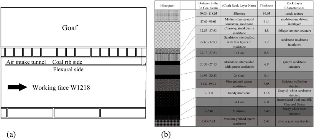
Figure 1. Working face layout and geological conditions. (A) Layout of the ventilation tunnel and working face of the W1218 Open-off Cut. (B) Geological conditions of the No. 3 coal seam.
According to geological surveys, the immediate roof of the No. 3 coal seam is primarily composed of mudstone, with local intercalations of siltstone and sandstone, varying in thickness from 0 to 12 m. The strata are characterized by well-developed fissures, loose and expansive rock mass, and high water absorption, resulting in poor surrounding rock properties. The immediate roof is made up of sandstone, with an average thickness of 8.2 m, containing some argillaceous materials. The floor is mainly composed of sandy mudstone, with a maximum thickness of 2.4 m and local inclusions of siltstone, while the lower part consists of high-strength sandstone. From shallow to deep, the surrounding rock exhibits a transition from weak strata to hard strata, with alternating layers of weak and hard rock, forming a complex structural profile. Although the immediate roof has relatively high strength, it is prone to softening under the influence of groundwater, which reduces the stability of the roof and poses a threat to the safety of the roadway surrounding rock. Figure 1B shows the geological conditions of the coal seams in the mining area.
The cross-sectional shape of the W1218 intake air roadway is rectangular, with a total length of 1954 m, a clear width of 4.8 m, and a clear height of 4 m. The roadway is supported using a combined anchoring, mesh, and cable support system, as shown in Figure 2.
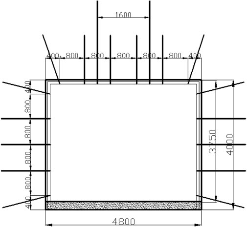
Figure 2. Cross-section support diagram of the W1218 ventilation tunnel.
Currently, the support parameters for the W1218 intake air roadway are as follows:
The sidewall support parameters are as follows: Each sidewall is equipped with five Φ22 × 2400 mm left-handed, non-ribbed anchor bolts, arranged symmetrically along the centerline of the roadway with a spacing of 800 mm × 800 mm. The anchor plates are high-strength, curved plates with dimensions of 170 × 170 × 12 mm. Both the sidewall roof and floor anchor bolts are installed 400 mm from the roof and are set at a 20° angle to the horizontal. A single reinforcement ladder beam, 3500 mm in length, is used for the sidewall support. The mesh is made of 10# steel wire, with a mesh size of 50 × 50 mm, and the side mesh dimensions are 3,600 × 900 mm.
The roof support parameters are as follows: Six Φ22 × 2,400 mm left-handed, non-ribbed anchor bolts are arranged with a spacing of 800 × 800 mm. The roof is supported by double-reinforced ladder beams made from Φ14 round steel, each 4,500 mm in length. The roof mesh has a mesh size of 50 × 50 mm, with dimensions of 5,400 × 900 mm. The roof cable anchors are spaced 1,600 × 1800 mm apart, each 6.2 m in length, with two anchors per row, symmetrically arranged along the centerline of the roadway roof.
The testing is conducted at the W1218 working face intake air roadway, with the testing area selected from two regions, C and D, as shown in Figure 3. Region C represents the coal rib of the goaf, and Region D represents the flexible support rib. The testing area is located 41.5–52.5 m behind the initial working face. Along the back of the working face (goaf), 14 measurement points are set, with the distance from each point to the first measurement point and point numbers ranging from B31 to B314. Region D contains anchor bolts constructed by the flexible support system. Measurement points are set at 1.6-m intervals along the back of the working face (goaf), with a total of 17 measurement points, numbered from B41 to B417. The selected measurement points in both regions correspond to sidewall anchor bolts. In the selected testing area, six testing cross-sections are arranged, as shown in Figure 3. The distances from the initial working face for cross-sections 1, 2, 3, and 4 are 21.2 m, 23 m, 28.8 m, and 30.5 m, respectively.
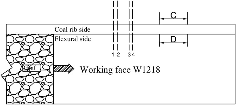
Figure 3. Layout of the testing area in the goaf of the W1218 working face.
Using the anchor bolt non-destructive testing system (Figure 4A), the changes in axial force of the anchor bolts in Regions C and D will be monitored. The objective is to analyze the variation pattern of sidewall anchor bolt forces. As the working face advances, continuous monitoring of the axial force of the anchor bolts in the measurement points of Regions C and D will be conducted, and the impact of the anchor bolt forces on the stability of the goaf will be analyzed. The axial force data from the anchor bolts in both regions will be compared with that of anchor bolts in stable areas, in order to assess the effectiveness of the flexible support system.
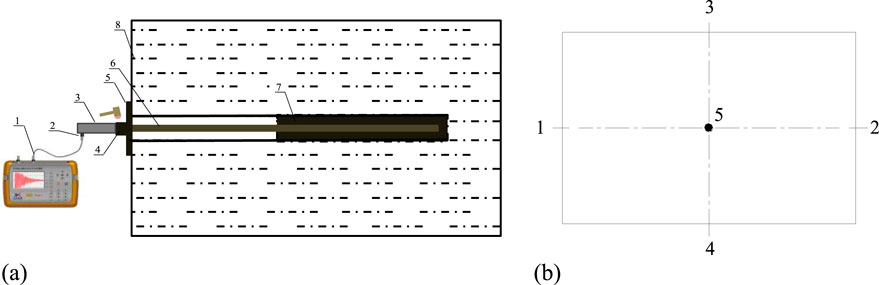
Figure 4. Non-destructive testing of anchor bolts and displacement monitoring cross-section. (A) Anchor rod non-destructive testing equipment and methods (1 - Bolt non-destructive testing instrument, 2 - Signal sensor, 3 - Sensor connection device, 4 - Fastening nut, 5 - Bolt tray, 6 - Bolt, 7 - Anchorage resin). (B) Monitoring section of the surface displacement of the tunnel surrounding rock.
Surface displacement monitoring of the roadway will be carried out using a cross-point layout for monitoring cross-sections, as shown in Figure 4B. Each cross-section will have three to five measurement points to monitor the displacement of the surrounding rock, including lateral squeezing of the two sidewalls, roof subsidence, convergence of the roof and floor, and bulging of the floor. The measurements will be taken using displacement gauges, convergence meters, or steel rulers.
According to the testing requirements, before the test, a section of rebar with a length of 200–300 mm and a diameter of 14–16 mm will be welded to the rear end of each measurement point, protruding 20 mm from the surface of the roadway. Then, a measurement ring will be installed onto the measurement point. The steel ruler handle of the convergence meter will be opened, and the hook at the end of the ruler will be pulled out and placed into the measurement point hole. After pulling the convergence meter to the other end, the hook of the ruler frame will be hung into the measurement point hole. The appropriate scale hole will be selected, the scale pin will be inserted into the hole, and the scale will be fixed to the coupling frame using the scale clips. Next, the fastening screws will be loosened, and the length of the sliding sleeve will be adjusted to apply initial tension to the steel ruler before tightening the fastening screws. The adjustment nut will be rotated until the white line in the spring force measurement window aligns with the markings on the window. Finally, the length of the steel tape ruler along the baseline of the coupling frame will be recorded, and the digital reading will be noted. For each baseline, the reading will be taken five times, and the average value will be used.
Through the non-destructive testing of anchor bolts, the axial force of the coal rib (Region C) and flexible support (Region D) anchor bolts in the goaf at different advancing distances of the working face were obtained, as shown in Figure 5.
(1) Variation of Goaf Anchor Bolt Axial Force with Advancing Distance of the Working Face
① During the advancement of the working face, the axial force of the anchor bolts in the rear goaf is significantly affected. As the advancing distance increases, the axial force on the coal rib and flexible support anchor bolts gradually increases. Furthermore, this increasing trend is independent of the location of the anchor bolts.
② A comparative analysis of the two sets of curves reveals that over 85% of the anchor bolts in the coal rib have an axial force greater than 6 tons. Among them, more than 50% have an axial force greater than 8 tons, and 25% of the anchor bolts have an axial force greater than 10 tons. In contrast, over 85% of the anchor bolts in the flexible support have an axial force of 5 tons or less, with most concentrated in the 2–4 ton range. Therefore, it can be seen that the flexible support creates a significant stress difference between the two sides of the goaf, which affects the stability of the goaf.
(2) Analysis of the Axial Force Difference Between the Two Sides of Goaf Anchor Bolts
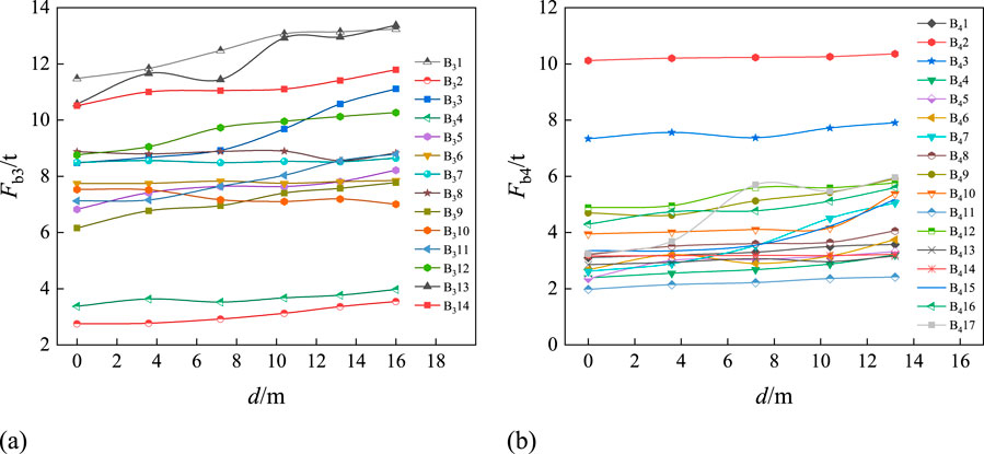
Figure 5. Variation curve of axial force in the goaf anchor rod with the advancement of the working face. (A) Coal side. (B) Flexible membrane side.
As shown in Figure 6, with the increase in the advancing distance, the axial force of the coal rib and flexible support anchor bolts in the goaf gradually increases, and the increase is approximately linear. The relationship between the two can be expressed as:
In this case, k represents the slope of the line, indicating the degree of influence that the advancement of the working face has on the axial force of the anchor bolts; δ represents the intercept of the line, indicating the initial axial force of the anchor bolts during the first test.
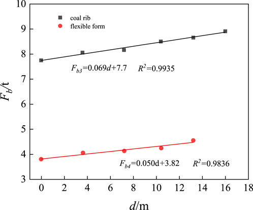
Figure 6. Variation curve of the average stress in the anchor rod with the advancement of the working face.
Figure 6 shows the variation curves of the average stress of the coal rib and flexible support anchor bolts in the goaf with the advancing distance. From the figure, we can observe the following:
① The average axial force of the coal rib anchor bolts is greater than that of the flexible support anchor bolts. For example, when d = 0, the former is 2.04 times larger than the latter, and when d = 10.4, it is 1.91 times larger;
② From the relationship formula between the average axial force of the coal rib and flexible support anchor bolts with the advancement of the working face, we can see that the slope of the coal rib anchor bolt axial force variation is 0.69, which is greater than that of the flexible support anchor bolts. This indicates that the mining activity of the working face has a greater impact on the coal rib;
③ Comparing the average axial force of the anchor bolts in the stable zone, it is observed that the average axial force of the coal rib anchor bolts is always greater than that of the stable zone anchor bolts during the advancement of the working face, whereas the average axial force of the flexible support anchor bolts is significantly smaller. This suggests that the coal rib undergoes more deformation in the goaf and is more prone to instability during its service life. In contrast, the flexible support experiences less deformation, providing good support, but there is significant waste in support efficiency.
One side of the goaf is the solid coal rib, while the other side consists of backfill. As the mining face advances, the overlying strata typically fracture into regular block shapes, forming a structure similar to a “masonry beam,” which is primarily formed by the mutual compression between the rock blocks. On the goaf side, the rock mass is divided and reorganized into three key blocks—A, B, and C—which are crucial for maintaining the stability of the goaf. As shown in Figure 7A, the distribution and interrelationships of the three key blocks (A, B, and C) are illustrated.
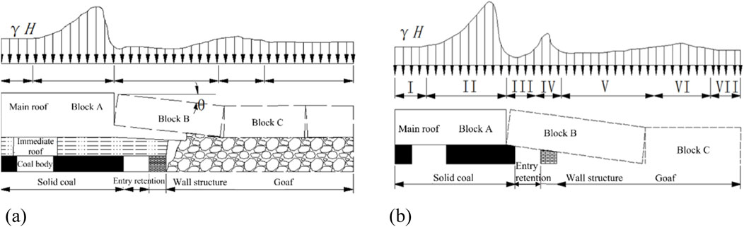
Figure 7. Stress distribution of surrounding rock and roof in retained roadway. (A) Surrounding rock stress in the left lane under soft roof conditions. (B) Roof stress distribution in the left lane under thick and hard roof conditions.
Under the mining conditions of a weak direct roof layer, as the mining face advances, the overlying strata gradually collapse. The collapsed gangue serves as a buffer layer for key blocks B and C, providing support, allowing key block B to form a stable “arch structure” with key blocks A and C at a small rotation angle (θ). This structure extends from the coal rib into the goaf, forming five stress zones, where the surrounding rock is in a low-stress zone, effectively protecting it. In contrast, under the condition of a thick and hard roof, due to the higher strength and thickness of the roof, its collapse process and periodic pressure are different from those of a weak roof layer. This results in new structural characteristics, placing higher demands on the stability of the goaf. Therefore, attention must be paid to its impact on mining to ensure safe operation.
According to the masonry beam theory, the following can be derived:
in the equation, h represents the thickness of the hard direct roof, and m represents the mining height.
Under the condition of a thick and hard roof, the roof forms a stable masonry beam structure, and the length of key block B can be determined either through field measurements or based on the ultimate span. Based on site observations, a stress model has been established (as shown in Figure 7B). As the mining face advances, key block B gradually exerts stress on the surrounding rock until it makes contact with the bottom and stabilizes. Since the gangue near the goaf side cannot provide buffering, key block B is supported by the floor, forming seven stress zones, with the wall area being a stress concentration zone. This may increase the instability and deformation risks of the surrounding rock. Moreover, the significant deformation of the backfill exerts additional pressure on the support system.
A large number of engineering practices have shown (Lian et al., 2023; Yuan et al., 2023) that the surrounding rock structure of the goaf differs significantly from that of a typical goaf, primarily in terms of stability and support requirements. When the overlying strata and the sidewall coal body are supported by a combined anchor-net-sling system, a cantilever beam structure often forms on one side of the goaf (as shown in Figure 8A). Due to the lack of solid support, the rock mass is suspended on the anchor-net-sling system, resulting in stress concentration at the root. Although this structure can partially support the rock strata, it also increases stress concentration in the surrounding rock, which may impact the stability of the goaf.
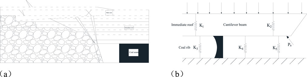
Figure 8. Schematic diagram of the cantilever beam structure and the mechanical model of the goaf. (A) Cantilever structure. (B) Mechanical model of gob-side entry retainingcantilever structure.
The stability of the cantilever beam structure is influenced by multiple factors, including the surrounding rock structure of the roadway, the strength of the backfill support body, and the strength of the coal rib. These factors interact with each other to determine the load-bearing capacity and stability of the cantilever beam. The length of the cantilever beam is closely related to the strength of the coal rib and the support resistance (as shown in Figure 8B). When the coal rib strength is high and the support resistance is large, the cantilever beam is shorter and more stable. Conversely, when the coal rib strength is low or the support is insufficient, the cantilever beam may extend, increasing the risk of instability.
The cantilever beam structure is subjected to various forces, including the overlying strata load, rock mass weight (K1), rock mass bearing capacity (K2), coal rib support force (K3), sidewall support resistance (K5), hydraulic prop bearing capacity (K4), and the tension force from the roof anchor cables (Pa). As shown in Figure 11, the mechanical model of the goaf is a cantilever beam structure, with one end supported by the fallen gob and the other end supported by the coal rib. The strength of the sidewall support is a key factor influencing stability. In the absence of sidewall support, a “decompression zone” forms in the goaf, and the cantilever beam structure may cause the coal rib to fracture due to rotational subsidence. If the sidewall support is insufficient, the roof may sink and delaminate, leading to potential fracture of the cantilever beam. However, when the support strength is high, roof fissures decrease, the stability of the cantilever beam improves, and the cantilever beam structure shifts towards the goaf.
A large body of theory and practice suggests (Fan et al., 2020; Luo et al., 2018) that the design of roadway retention should first explore the structural characteristics and failure patterns of the overlying strata in the mined-out area. Under the influence of intense movements in the overlying rock layers above the working face, roof failure triggers significant mining pressure phenomena and deformation. The key layer theory has proven effective in studying roof stability, and the failure and movement of the primary roof have the most significant impact on the mined-out area. Therefore, it is essential to study the fracture, movement, and stability patterns of the primary roof to understand its impact on the stability of the surrounding rock structure. As the mining face advances, the roof continuously collapses. Upon initial pressure, an “O-X” fracture forms, and after periodic fracturing, rock blocks form a masonry beam structure, ultimately evolving into an arcuate triangular block structure. Figure 9A illustrates the fracture patterns of the primary roof.
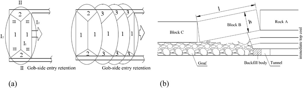
Figure 9. Failure modes of the main roof and roof in the goaf area. (A) Basic roof failure modes in the goaf. (B) Collapse mode of the roof rock in the goaf.
Compared to traditional tunnels, mined-out areas have unique characteristics. They are significantly influenced by mining-induced dynamic pressure, with long lag periods, large additional stresses, and severe surrounding rock damage, making it difficult to maintain stability. Studying the activity patterns of the roof in mined-out areas essentially involves analyzing the failure modes of the overlying rock. The surrounding rock activity is primarily influenced by the movement patterns of the primary roof above the mining face.
As shown in Figure 9B, after the advancement of the mining face, the overlying rock mass in the mined-out area gradually fractures. With the coal seam extraction, mining-induced effects cause irregular caving and subsidence of the immediate roof, leading to delamination of the primary roof. After the caving of the immediate roof, the rock mass fractures, rotates, or bends and subsides, ultimately forming a hinged structure composed of rock mass A, block B, and block C (see Figure 9B). The degree of filling of the waste rock in the mined-out area and the fracture pattern of the primary roof determine the movement behavior of the primary roof. Once the collapse of the overlying rock mass stabilizes, the edge or lower part of block B becomes the location of the mined-out area. Therefore, block B is a key factor influencing the stability of the mined-out area.
To deeply analyze the relationship between anchor rod axial force and stratum deformation, as well as the deformation characteristics of the goaf area under dynamic pressure, we conducted systematic deformation monitoring of the coal ribs and roof in the W1218 working face goaf area. As the working face progresses, the displacement changes of the tunnel surrounding rock at different monitoring points are shown in Figure 10.
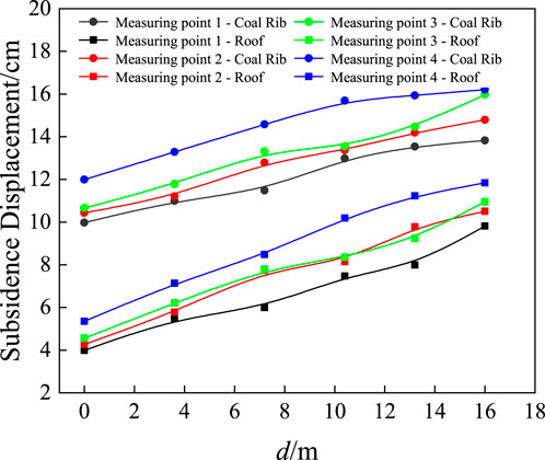
Figure 10. Variation of tunnel surrounding rock deformation with the advancement of the working face at different measuring points.
Figure 10 shows that as the monitoring points move further from the working face, the deformation of the tunnel surrounding rock gradually increases. The deformation on the coal rib side is significantly greater than the roof subsidence, with the difference ranging from 3 to 6 cm. In the later monitoring stages, the roof subsidence exceeds 10 cm, and the coal rib deformation exceeds 14 cm, with the deformation rate slowing down. As the distance from the working face increases, the surrounding rock deformation tends to stabilize due to the gradual stabilization of the overlying rock layer, reducing its impact on the surrounding rock. The changes in anchor rod axial force closely follow the deformation pattern of the surrounding rock, exhibiting significant coordinated variation, which provides important reference for support design and stability analysis.
Based on the construction of the W1218 working face goaf, a numerical calculation model was established (see Figure 11). The model dimensions are 200 m × 120 m × 60 m, and the physical and mechanical parameters of the surrounding rock are shown in Table 1. Figure 11A is the front view of the 3D mechanical model, where the shaded area represents the coal seam, and the goaf is located on both sides of the working face. A uniform load P is applied to simulate the effect of the overlying rock, with horizontal displacement constrained. The top boundary is set as a free surface. Figure 11B is the I-I plane section, where the slanted dashed line area represents the mining area, and steel-reinforced concrete support is injected according to the calculation scheme.
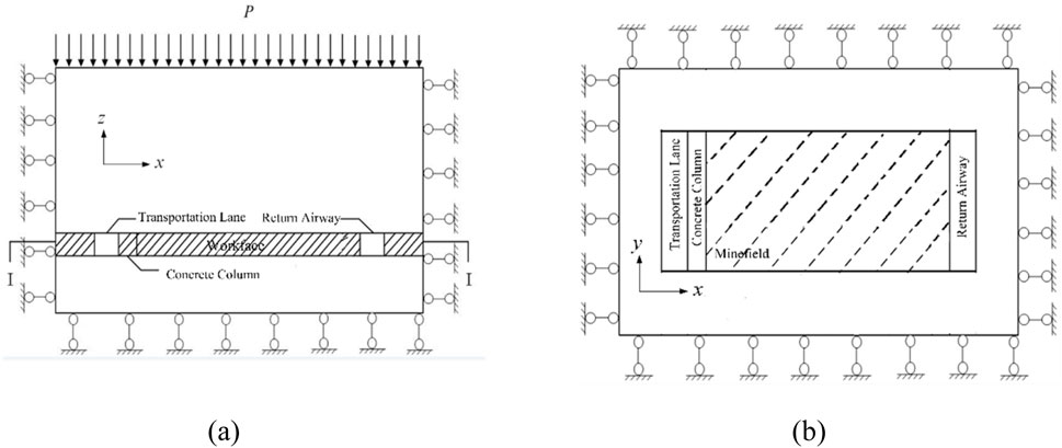
Figure 11. Numerical simulation calculation model. (A) Front view. (B) I-I Section view.

Table 1. Physical and Mechanical Parameters of Coal Seam and its Overlying and Underlying Rock Layers.
This numerical simulation mainly calculates the changes in the surrounding rock stress and deformation characteristics, as well as the anchor bolt force characteristics along the goaf tunnel, as the mining face advances. The numerical calculation scheme follows the actual site arrangement as described in Section 2.2.
Figure 12 show the vertical stress distribution and deformation characteristics of the surrounding rock in the roadway before mining, respectively. From Figure 12A, it can be observed that after the excavation of the goaf, the surrounding rock stress is redistributed and gradually reaches a new equilibrium state. The compressive stress on the goaf roof decreases, while the compressive stress on both sides of the coal pillars increases significantly, leading to stress concentration and a wide-ranging effect. Under high stress, deformation and failure, such as compression, shear, and crack propagation, occur at the edges of the goaf coal body, causing a reduction in bearing capacity, and ultimately forming a low-stress unloading zone.
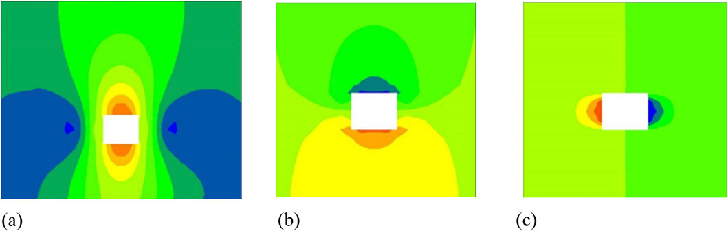
Figure 12. Stress and deformation characteristics of surrounding rock in roadways. (A) Stress Contour Map of Tunnel Surrounding Rock. (B) Vertical displacement contour map of the tunnel surrounding rock. (C) Horizontal displacement contour map of the tunnel surrounding rock.
After the excavation of the goaf, the stress within the rock mass is redistributed and gradually reaches a new equilibrium state. As seen in Figures 12B, C, with the excavation of the goaf, the compressive stress on the roof decreases, while the compressive stress on both sides of the coal pillars increases significantly, leading to stress concentration and a wide-ranging impact. Under such high-stress conditions, the coal body at the edges of the goaf may undergo varying degrees of deformation and damage, reducing its bearing capacity, and ultimately forming a low-stress unloading zone.
After the excavation of the goaf, the stress in the surrounding rock is redistributed, mainly because the balanced stress field is disrupted. The excavation of the goaf causes the rock mass to lose partial support, leading to stress concentration. Due to the different stresses acting on the roof, floor, and coal pillars, the rock mass moves toward the low-stress area, resulting in deformation and displacement. The convergence of the roof and floor is relatively small, while the convergence at the middle of the two pillars is larger, mainly because the two-pillar areas are subject to concentrated stress and the rock layers are weaker. As shown in Figures 12B, C, the convergence of the roof and floor is 4.3 cm, while the convergence at the middle of the two pillars is 15.2 cm, reflecting the different responses of the surrounding rock under stress redistribution.
During the mining recovery process, as the coal body gradually disappears, significant changes occur in the stress distribution along the edges of the mined-out area. Figure 13 shows the vertical stress distribution of the benchmark section of the mined-out area when the working face advances to 40 m. From the figure, it is clear that the mined-out area has had a significant impact on the surrounding rock stress within a 20-m range, causing a noticeable change in the stress conditions of this region. This redistribution of stress may further affect the stability of the surrounding rock.
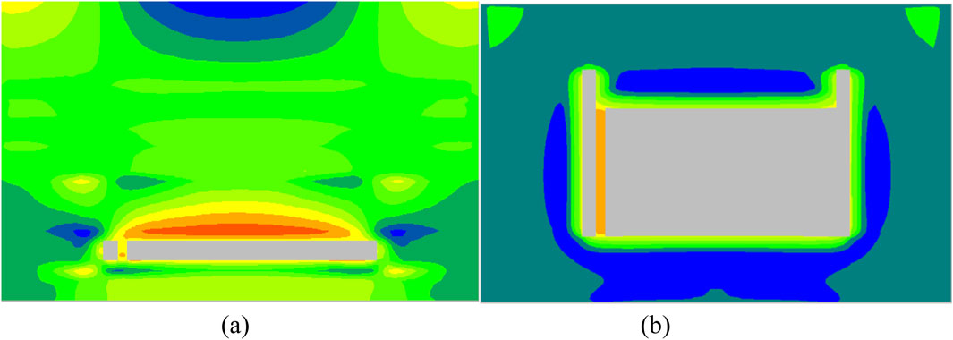
Figure 13. Vertical stress contour map before the advancement of the working face. (A) Front view. (B) Top view.
Figure 14 shows the dynamic characteristics of the vertical stress distribution on the benchmark surface as the working face advances. With the progression of the working face, the stress distribution in the tunnel surrounding rock undergoes significant changes. On the coal rib side, due to the compressibility of the coal body, as the mined-out area expands, the coal body bears larger compressive stresses and deforms, resulting in stress accumulation and release. The vertical stress initially increases and then decreases. On the soft support side, the concrete wall has low deformability and cannot release stress through deformation, leading to continuous accumulation of compressive stress, which eventually exceeds the stress on the coal rib side. This difference reflects the different stress response mechanisms of the materials on both sides under external pressure.

Figure 14. Vertical stress distribution on the reference surface at different advancing distances. (A) d = 3.6 m (B) d = 7.2 m (C) d = 10.4 m (D) d = 13.2 m.
By extracting the axial forces of rock bolts at the reference plane, the variation law of axial forces at different advancing distances was analyzed, and the corresponding curves were plotted (as shown in Figure 15). As seen from the figure, with the advance of the working face, the axial forces of rock bolts at all positions generally increase. The axial forces of the bolts in the coal rib and the roof show a linear growth trend, while the axial force in the soft-cushion rib initially increases and then tends to stabilize. Further analysis of the average axial forces of bolts at different positions (as shown in Figure 15D) shows that as the advancing distance increases, the average axial forces in the coal rib, roof, and soft-cushion rib increase by 34.52% (from 8.96 t to 12.05 t), 31.36% (from 5.68 t to 7.46 t), and 9.38% (from 3.52 t to 3.85 t), respectively. Among these, the axial force of bolts in the coal rib is significantly higher than in the roof and soft-cushion rib, and at the same advancing distance, the axial force in the coal rib is about three times that in the soft-cushion rib.
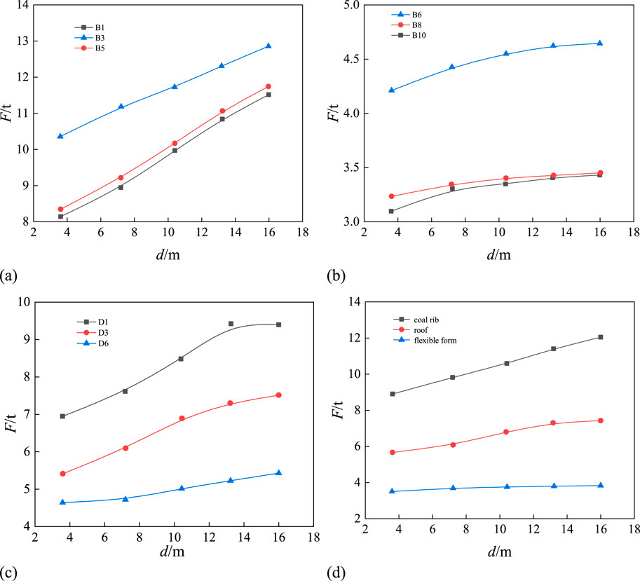
Figure 15. Variation curve of anchor rod axial force with advancement distance. (A) Coal side. (B) Flexible membrane side. (C) Roof. (D) Comparison of average axial force.
During the advancement of the working face, the changes in the axial forces of the rock bolts reflect the response mechanism of the surrounding rock under dynamic loading. The axial forces of the rock bolts in the coal rib and roof show a linear increase, mainly due to the expansion of the mined-out area, which gradually increases the vertical stress on the surrounding rock of the coal rib and roof. This forces the bolts to provide greater support to resist the deformation of the surrounding rock. Particularly in the coal rib, due to its higher compressibility, significant deformation occurs under dynamic pressure, leading to a rapid increase in the axial force of the bolts. In contrast, the axial force in the soft-cushion rib initially increases quickly but then stabilizes, indicating that the soft-cushion concrete wall has a higher stiffness and lower deformability, limiting the deformation of the surrounding rock. Once the axial force reaches a certain value, it no longer increases significantly. The different stress distribution and deformation characteristics reflect the differences in the pressure experienced by the coal rib and the soft-cushion rib during the advance of the working face, as well as their different support requirements for the bolts.
During the advancement of the working face, the deformation of surrounding rock is the fundamental cause of changes in surrounding rock stress and anchor rod axial force. Figures 16, 17 show the deformation cloud maps of the surrounding rock in the horizontal and vertical directions, respectively, as the working face progresses. By comparing the deformation of the coal rib and soft rock rib, it can be observed that the deformation amount and extent of the coal rib are both greater than those of the soft rock rib.
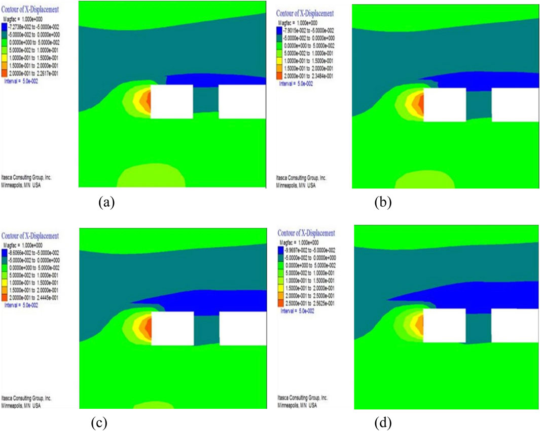
Figure 16. Horizontal (X) direction deformation contour map of the surrounding rock after the advancement of the working face. (A) d =3.6 m (B) d = 7.2 m (C) d = 10.4 m (D) d = 13.2 m.
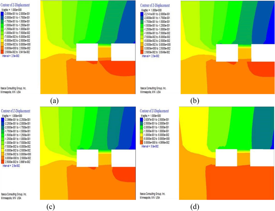
Figure 17. Vertical (Z) direction deformation contour map of the surrounding rock after the advancement of the working face. (A) d =3.6 m (B) d = 7.2 m (C) d = 10.4 m (D) d = 13.2 m.
By analyzing the maximum deformation of the coal rib, roof, and soft rock, the deformation variation curve of the surrounding rock with the progression of the working face is obtained (see Figure 18). From the figure, it is clear that as the working face advances, the deformation of the surrounding rock increases linearly. During the progression of the working face from 3.6 m to 13.2 m, the deformation of the coal rib increased by 13.31% (from 22.62 cm to 25.63 cm), the roof increased by 13.72% (from 12.53 cm to 14.25 cm), while the deformation of the soft rock rib only increased by 2.26% (from 2.21 cm to 2.26 cm). This variation is mainly influenced by the expansion of the mining area and the physical properties of the surrounding rock. The coal rib has a large compressibility and lower stiffness, resulting in more significant deformation, while the stiffness of the soft rock material is relatively high, leading to almost no deformation. As a result, it cannot release the accumulated stress through deformation, and although the anchor rod axial force is smaller, the internal stress of the soft rock rib is higher.
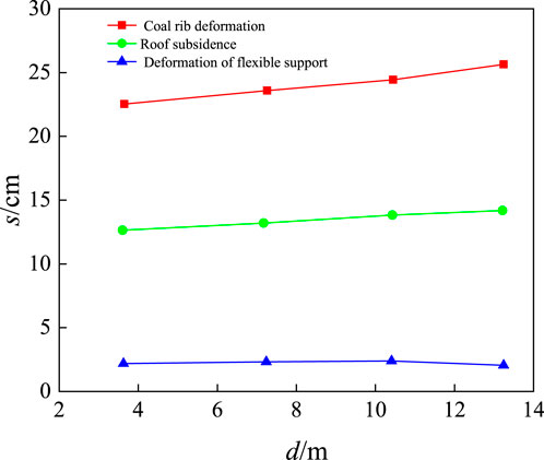
Figure 18. Variation curve of tunnel surrounding rock deformation with the advancement of the working face.
To further analyze the impact of the advancement of the working face on the axial force of anchor bolts at different locations along the roadway, anchor bolts B31, B33, B311 in the coal rib and B41, B45, B411 in the soft support side were selected for numerical simulation and field measurement comparison (see Figure 19). From the figure, it can be seen that with the advancement of the working face, both the axial forces of the coal rib anchor bolts and the soft support side anchor bolts gradually increase, but the axial force and its increase in the coal rib bolts are significantly higher than those in the soft support side bolts.Moreover, the comparison between the numerical simulation results and the measured data shows that, except for the initial section of bolt B41, the measured axial forces are generally higher than the numerical simulation values. The numerical simulation data display a linear growth trend, while the measured data show a clear nonlinear variation. Despite this, the overall trend of change in the numerical simulation and the measured data is consistent, effectively reflecting the actual variation characteristics of anchor bolt forces.
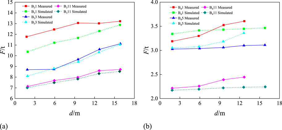
Figure 19. Comparison of changes in anchor rod axial force. (A) Coal side. (B) Flexible membrane side.
The axial force of anchor bolts is closely related to the mechanical properties of the surrounding rock. During the advancement of the working face, the stress state around the mined-out area undergoes significant changes, leading to an increase in the axial force of the anchor bolts. The differences in the forces on the coal rib anchor bolts and the soft support anchor bolts are primarily due to the differing properties and structures of the surrounding rock they support. Coal rib anchor bolts are usually located in stress concentration zones, where they bear higher forces. Particularly when the working face is near, the surrounding rock experiences large compressive and shear stresses, causing a rapid increase in the axial force of the anchor bolts. In contrast, the stress distribution in the regions supported by soft support anchor bolts is more uniform, leading to slower and smaller increases in axial force. In numerical simulations, to simplify calculations, the mechanical properties, structure, and deformation process of the surrounding rock and mined-out area are often simplified, potentially overlooking key factors such as the distribution of rock fractures, mechanical heterogeneity, and the randomness of dynamic loads. These factors result in the actual axial force distribution of anchor bolts being nonlinear and random, with measured data typically being higher than simulated results, and the variation trend being more complex. Additionally, the dynamic loads generated during the advancement of the working face (e.g., mining-induced stresses) have a significant impact on the stress state of the anchor bolts. Dynamic loads usually manifest as transient stress waves, causing the anchor bolts to experience sudden increases in stress over short periods. Numerical simulations typically focus on steady-state or quasi-steady-state stress changes, making it difficult to capture these transient effects. As a result, the simulation results tend to show linear growth, which underestimates the actual stress changes.
According to the testing plan, combined with numerical simulation and field measurement results, the curves of the lateral convergence of both sides and roof subsidence with advancing distance were obtained, as shown in Figure 20.
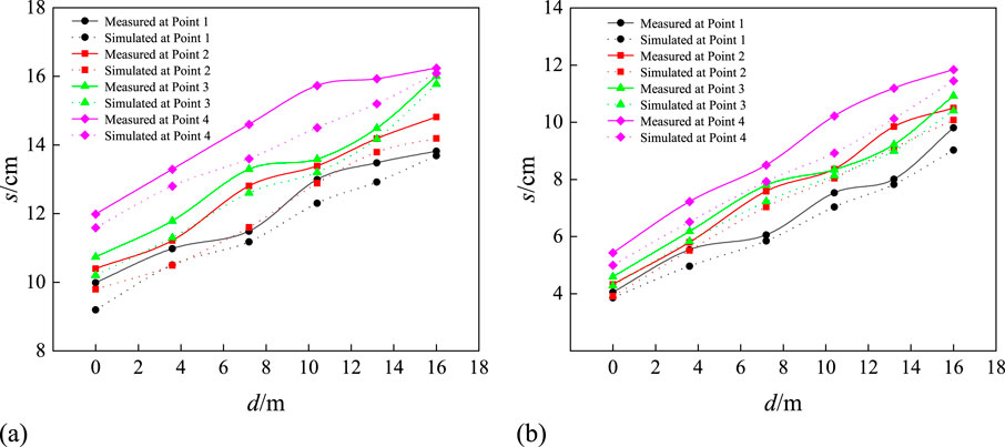
Figure 20. Comparison of tunnel surrounding rock deformation characteristics. (A) Amount of convergence of both sides. (B) Amount of roof subsidence.
The numerical simulation results indicate that as the working face advances, the lateral convergence of both sides and roof subsidence increase linearly. As the working face progresses, the lateral convergence at the four observation points increased by 4.5 cm, 4.4 cm, 5.6 cm, and 4.5 cm, respectively, while the roof subsidence increased by 5.6 cm, 6.2 cm, 6.1 cm, and 6.4 cm, respectively. This shows that as the advancing distance increases, the rate of increase in roof subsidence gradually becomes larger. In addition, for the same advancing distance, the lateral convergence of both sides is greater than the roof subsidence, primarily due to the greater compressive deformation of the coal rib.
By comparing the numerical simulation results with the field measurement data, it was found that the deformation characteristics of the surrounding rock and the changes in anchor rod axial force exhibit a high degree of similarity. The numerical simulation shows that the lateral convergence of both sides and roof subsidence increase linearly as the working face advances. This is mainly based on the assumption that the surrounding rock behaves as an elastoplastic material, and that the stress field around the mined-out area changes uniformly with the advancement of the working face. In the simulation, the surrounding rock material is typically simplified as a homogeneous, continuous medium, which causes stress transfer and deformation responses to exhibit a regular linear relationship, leading to the lateral convergence and roof subsidence increasing linearly with the advancing distance. However, in actual engineering, the surrounding rock often displays more complex mechanical behavior, such as uneven stress distribution, crack development, and dynamic response, which causes the actual deformation characteristics to deviate from the simulation results. The deformation process becomes more nonlinear and irregular.
As the working face advances, the surrounding rock not only experiences stress concentration from the roof and both sides, but also undergoes uneven failure and deformation, particularly in regions where stress is concentrated, such as the coal ribs and the roof. These deformations cause the formation of cracks within the rock mass, significantly affecting the stiffness and stability of the surrounding rock, which in turn exacerbates the deformation. As a result, the measured results typically show larger deformation values than the numerical simulation, and this difference gradually increases with the advancing distance. Especially in the coal ribs, the coal seam is relatively soft and brittle, so under compression, it is prone to larger plastic deformations, which leads to a significantly greater lateral convergence than roof subsidence. This is particularly noticeable in practical engineering because the coal ribs are more likely to undergo compressive failure, resulting in larger displacements. Numerical simulations, however, often simplify the assumptions about the surrounding rock, failing to fully account for the effects of fragmentation and discretization on deformation. These simulations usually only capture the elastoplastic deformation of the surrounding rock. Furthermore, in the numerical simulation, the roof subsidence gradually increases with the advancing distance, reflecting the gradual loss of load-bearing capacity of the roof under the support system’s influence. Once the working face advances to a certain distance, the cantilever beam effect of the roof weakens, reducing the support effect and leading to an increase in subsidence. In contrast, the measured data may reveal local delamination or fractures in the roof, phenomena that are often difficult to capture comprehensively in numerical simulations.
Through field measurements and numerical simulation analysis, it can be observed that as the working face advances, the anchor bolt axial force changes in the stable zone and flexible support zone are minimal, but the surrounding rock deformation exhibits asymmetric characteristics. The anchor bolt support on the flexible side is often wasted, while the axial force on the coal rib side is larger, and the surrounding rock deformation is more pronounced. Therefore, the support plan should focus on strengthening the coal rib and side roof support, while reducing the anchor bolt strength on the flexible side to control harmful deformation. Based on prior research, a non-destructive testing optimization design method for anchor bolt support in the goaf is proposed, which includes five steps: preliminary design, monitoring and detection, modeling, verification, and re-optimization. This method combines field data with numerical simulations to optimize anchor bolt force analysis and the support scheme, ensuring engineering requirements while saving costs.
The core of the asymmetric support design lies in adopting differentiated support measures based on the actual stress and deformation characteristics of the surrounding rock. It mainly includes three aspects: Firstly, drawing on the concept of low-density, high-strength support, reduce the bolt density on the flexible side of the ribs while increasing the bolt pre-tension to enhance the support strength, provided that the engineering requirements are met; the bolt density on the coal rib side remains unchanged, but the support strength is increased. Secondly, regarding the asymmetric deformation of the goaf and the stress condition of the roof bolts, the bolts on the flexible side of the roof experience less stress, while those on the coal rib side experience more, indicating that the roof on the coal rib side is the key to instability and failure. Therefore, the density of roof bolts on the flexible side can be reduced along the centerline of the tunnel, while increasing the pre-tension to effectively control the surrounding rock deformation and reduce the support cost. Finally, based on the distribution characteristic that “coal rib deformation is greater than roof deformation, which is greater than the flexible side deformation,” the pre-tension of the coal rib bolts should be increased to strengthen the support on the coal rib side and suppress harmful deformations. Based on the above strategies, the optimized method for asymmetric support can be summarized as follows: Using the tunnel centerline as a reference, reduce the bolt density on the flexible side of the rib and roof, appropriately increase the pre-tension and support strength to save costs; meanwhile, maintain the support density on the coal rib side unchanged, increase the pre-tension of the bolts, strengthen the support on the coal rib side, and control deformations. The specific support parameters of the optimization plan are shown in Figure 21:
① The coal rib bolts are of type Φ22 × 2400 mm left-handed non-threaded ribbed bolts, arranged symmetrically along the tunnel centerline, with five bolts per side. The three middle bolts are arranged vertically to the coal rib, and two bolts at the rib corners are arranged at a 30° angle to the horizontal direction. The spacing between the bolts is 800 × 900 mm, with an initial design pre-tension force of 40 KN. The flexible side bolts are of type Φ22 × 2,400 mm left-handed non-threaded ribbed bolts, arranged symmetrically along the tunnel centerline, with four bolts per side. The two middle bolts are arranged vertically to the coal rib, and two bolts at the rib corners are arranged at a 30° angle to the horizontal direction. The spacing between the bolts is 1,000 × 900 mm, with an initial design pre-tension force of 55 KN.
② The roof bolts are of type Φ22 × 2,400 mm left-handed non-threaded ribbed bolts, with six bolts arranged per cross-section. Based on the tunnel centerline as the reference, the spacing of the bolts on the coal rib side of the roof is 800 × 900 mm, and the spacing on the flexible side of the roof is 1,000 × 900 mm. The four middle bolts are installed vertically to the roof, and the two bolts at the rib corners are arranged at a 30° angle to the vertical direction. The initial design pre-tension force is 35 KN. The roof anchor cables are of type 2 Φ22 × 5,200 mm 1 × 7 strand high-strength low-relaxation steel strands, arranged with a spacing of 2,700 × 1,800 mm, perpendicular to the tunnel roof. The initial design pre-tension force is 85 KN.
③ The anchor plate is a curved high-strength plate with dimensions of 170 × 170 × 12 mm. The steel ladder beams are made from Φ14 round steel. On the coal rib side, the anchor bolt uses a single-bar ladder beam with a length of 3400 mm. On the flexible side, the anchor bolt uses a single-bar ladder beam with a length of 3200 mm. The roof anchor bolt uses a double-bar ladder beam with a length of 4,600 mm, and the roof anchor cable uses a double-bar ladder beam with a length of 2900 mm. The mesh specifications are as follows: both the roof and the two ribs use #10 iron wire metal mesh, with a mesh size of 50 × 50 mm. The dimensions of the roof mesh are 4,600 × 1,000 mm, the coal rib mesh is 3,400 × 1,000 mm, and the flexible side mesh is 3,200 × 1,000 mm.
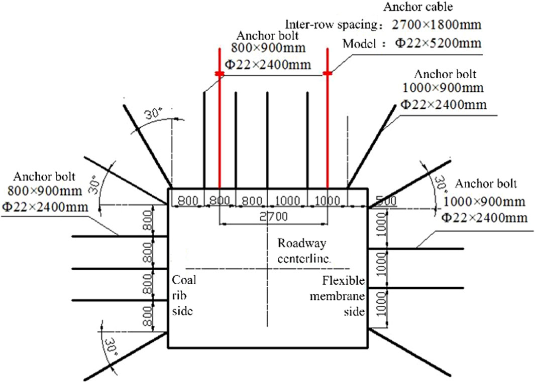
Figure 21. Cross-section support diagram of the optimized solution for the E1310 goaf.
To verify the support effect of the optimized support scheme, numerical simulations are conducted using Flac3d software to analyze the support effects of the anchor bolts in the stable zone in front of the mining face and the flexible model support zone behind the mining face. The surrounding rock deformation and plastic zone distribution of the two optimization schemes are compared in order to further optimize the tunnel support parameters.
According to the measurement results, compared to the original support, the optimized solution has reduced the roof subsidence, floor heave, and sidewall convergence by 16.51% (from 22.4 mm to 18.7 mm), 7.76% (from 11.6 mm to 10.7 mm), and 4.45% (from 98.7 mm to 94.3 mm), respectively. This indicates that although the support density of the optimized scheme is reduced, the surrounding rock deformation is more effectively controlled by increasing the anchor pre-tension and support strength. The main mechanism behind this is that the optimized scheme more precisely matches the stress characteristics of the surrounding rock. By reducing the support density on the flexible side and increasing the anchor pre-tension, the initial support effect is enhanced, effectively restraining the rock deformation. Meanwhile, strengthening the support strength at key locations such as the coal rib and roof increases the support for areas with significant deformation, preventing the expansion of local failures. As a result, the overall displacement and deformation of the surrounding rock are reduced.
According to the measurement results, the optimized support scheme demonstrates significant advantages in controlling surrounding rock deformation compared to the original support scheme. Under the optimized scheme, the roof subsidence decreased by 11.57% (from 108.9 mm to 96.3 mm), the floor heave decreased by 3.45% (from 31.9 mm to 30.8 mm), and the coal wall deformation decreased by 5.46% (from 62.3 mm to 58.9 mm). These results indicate that, although the support density has been reduced, the optimized scheme more effectively suppressed the rock mass deformation by enhancing the support strength.
The traditional support scheme ensures rock mass stability through higher support density, but this often leads to material wastage and increased costs. The optimized scheme, on the other hand, adjusts the support density based on rock mass deformation characteristics. For areas with smaller deformation, such as the flexible support side, reducing the support density does not affect overall stability. At the same time, increasing the anchor pre-tension enhances the support strength, allowing the system to provide adequate stiffness and load-bearing capacity even at lower densities, effectively controlling initial deformation and improving resistance to later large deformations. For critical areas such as the coal rib and roof, the optimized scheme strengthens the coal rib side support, distributing concentrated stress and preventing local failure. Additionally, it moderately strengthens the roof support to reduce subsidence and avoid excessive deformation, ensuring the overall stability of the goaf.
Based on the above analysis, the optimized support scheme is now adopted for the E1310 working face goaf, and the monitoring and detection of anchor rod forces and roadway surrounding rock deformation are conducted. Additionally, a comparative analysis of the supporting cost of the surrounding rock before and after optimization will be performed. Considering the actual site conditions and the ease of construction, the top plate support form in the optimized scheme will be further optimized before being applied to the actual engineering.
Figure 22 shows the support cross-section of the E1310 goaf. The specific support parameters are as follows:
(1) The coal rib anchor is a Φ22 × 2400 mm left-handed, ribless anchor. It is symmetrically arranged along the centerline of the roadway, with five anchors per side. The middle three anchors are arranged perpendicular to the coal rib, and the two anchors at the ribs are arranged at a 30° angle to the horizontal direction. The spacing between anchors is 800 × 900 mm, with a designed initial prestress of 40 kN. The flexible seam side anchors are also Φ22 × 2400 mm left-handed, ribless anchors. They are arranged symmetrically along the centerline of the roadway, with four anchors per side. The middle two anchors are arranged perpendicular to the coal rib, and the two anchors at the ribs are arranged at a 30° angle to the horizontal direction. The spacing between anchors is 1,000 × 900 mm, with a designed initial prestress of 55 kN.
(2) The roof anchors are Φ22 × 2400 mm left-handed, ribless anchors. Six anchors are arranged per section, with a spacing of 900 × 900 mm. The middle four anchors are arranged perpendicular to the roof, and the two anchors at the ribs are arranged at a 30° angle to the vertical direction. The designed initial prestress is 35 kN. The roof anchor cables are two Φ22 × 5200 mm 1 × 7 high-stress low-relaxation steel strands. They are arranged perpendicular to the roof of the roadway, with a spacing of 2,700 × 1800 mm. The designed initial prestress is 85 kN.
(3) The anchor bearing plates are high-strength curved plates with dimensions of 170 × 170 × 12 mm. The steel ladder beams are made of Φ14 round steel. For the coal side anchors, a single-reinforced ladder beam of 3400 mm in length is used; for the flexible side anchors, a single-reinforced ladder beam of 3,200 mm in length is used. The roof anchors use double-reinforced ladder beams of 4,700 mm in length, and the roof anchor cables use double-reinforced ladder beams of 2,900 mm in length. The anchor mesh specifications are as follows: both the roof and both sides of the roadway use 10# iron wire mesh with a mesh size of 50 × 50 mm. The roof mesh dimensions are 4,700 × 1,000 mm, the coal side mesh dimensions are 3,400 × 1,000 mm, and the flexible side mesh dimensions are 3,200 × 1,000 mm.
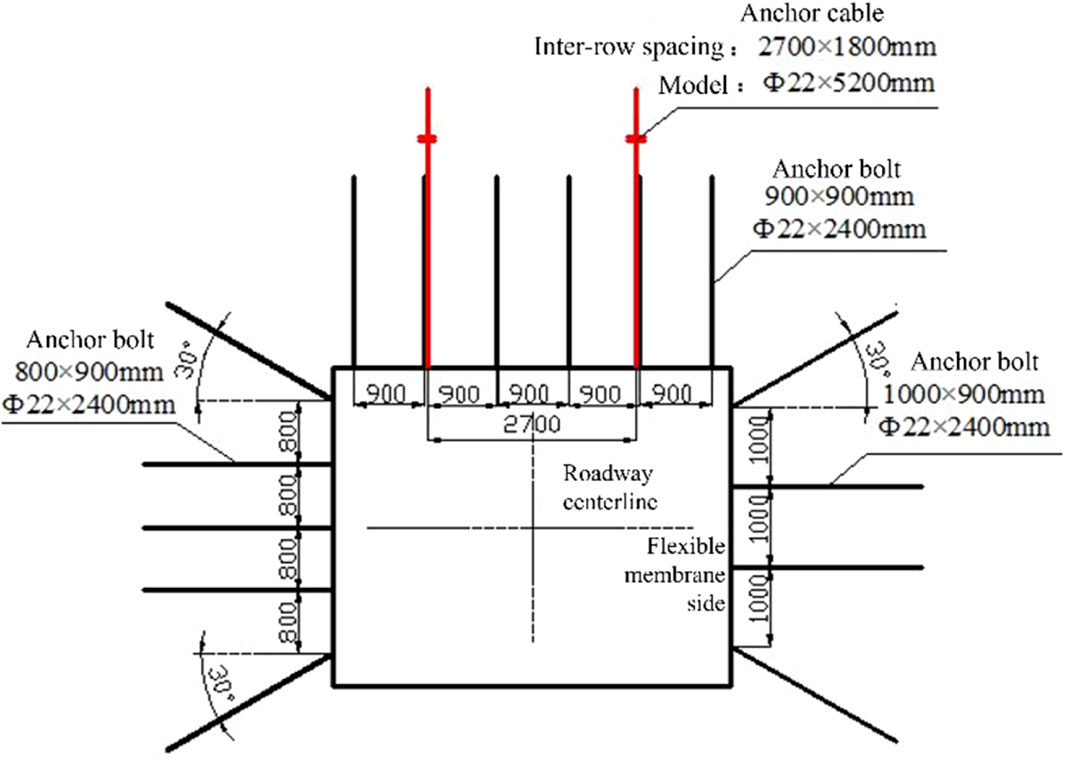
Figure 22. Cross-section support diagram of the E1310 goaf.
After the application of the optimized scheme, since the working face has not yet been mined, it is currently only possible to detect and monitor the anchor rod stress and surrounding rock deformation in the stable period of the goaf to verify the support effect of the optimized scheme. In this detection, four anchor rods were randomly selected from the same cross-section of the goaf, and their anchorage lengths and stress conditions were subjected to non-destructive testing. The following are the specific detection results.
In the E1310 goaf area, the bolt length detection results are as follows: for the roof bolts, the free section length is 700 mm, the anchored section length is 1,670 mm, the total length is 2,370 mm, and the total length error is 0.1%; for the coal wall bolts, the free section length is 1,200 mm, the anchored section length is 1,120 mm, the total length is 2,320 mm, and the total length error is 0.3%; for the flexible form sidewall bolts, the free section length is 1,530 mm, the anchored section length is 750 mm, the total length is 2,280 mm, and the total length error is 5.0%; for another set of coal wall bolts, the free section length is 1,150 mm, the anchored section length is 1,150 mm, the total length is 2,300 mm, and the total length error is 4.2%. According to the testing results, the anchorage length of the anchor rods is approximately 1,160 mm, indicating that the construction quality of the tested anchor rods is good.
As shown in Table 2, the axial force of the roof anchor rods in the E1310 goaf is 5.87 tons, the axial force of the coal side anchor rods is approximately 7.2 tons, and the axial force of the soft rock side anchor rods is 7.84 tons. All these values are significantly lower than the anchor rod’s ultimate bearing capacity of 15 tons, indicating that the anchor rods effectively fulfill their anchoring function. Furthermore, they retain a substantial bearing capacity for the recovery phase, essentially ensuring the overall safety and stability of the goaf.
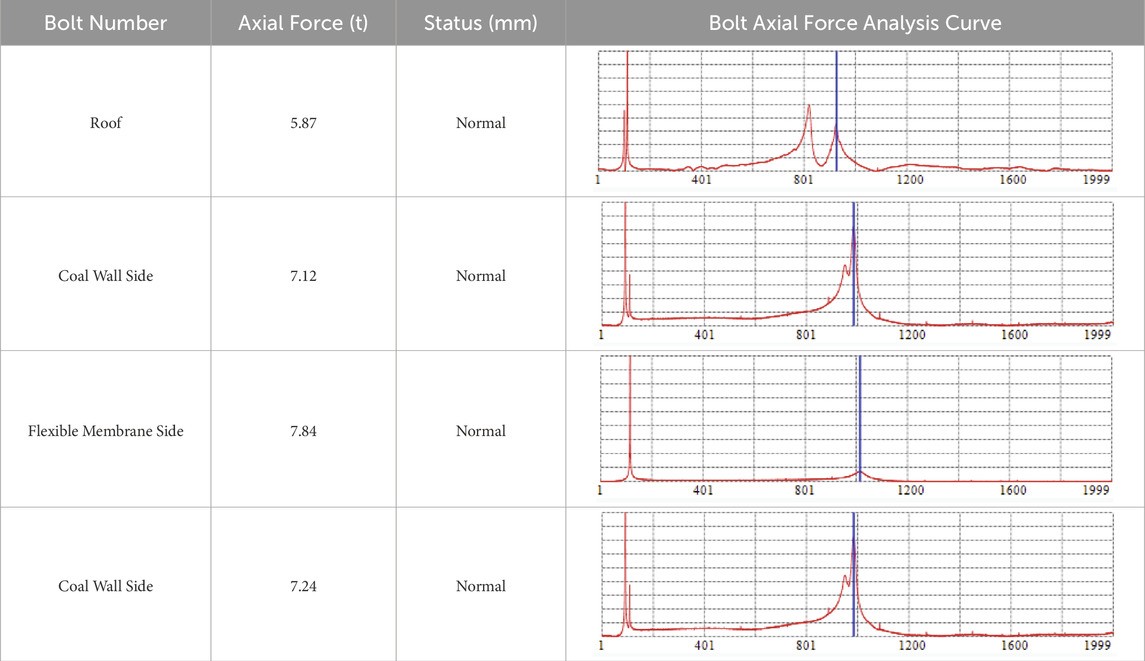
Table 2. Anchor rod axial force detection results.
To evaluate the support effect in the goaf, a measurement point was placed 200 m in front of the working face in the stable area. The top plate subsidence, floor heave, and rib convergence of the goaf were monitored. The surface displacement versus time curve is shown in Figure 23.
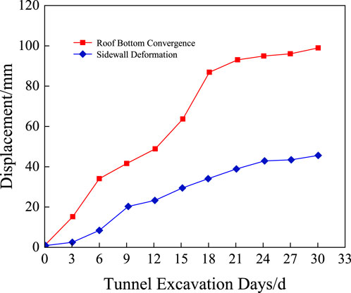
Figure 23. Surface displacement of the E1310 goaf.
From Figure 23, it can be seen that under the optimized support scheme, as the excavation time of the goaf increases, the convergence of the top and bottom plates and the ribs gradually increases, but the rate of increase slows down over time. After approximately 18 days, the surrounding rock deformation tends to stabilize, with the rib convergence amount reaching 98.6 mm and the top and bottom plate convergence amount reaching 45.3 mm. The deformation characteristics show that the rib deformation is more significant than the top plate, indicating that the disturbance stress in the goaf has a greater impact on the ribs. By analyzing the data, it can be concluded that the optimized scheme effectively reduced the surrounding rock deformation, particularly in terms of rib and top plate convergence, both of which are controlled within acceptable limits. This scheme performs well in controlling deformation and mitigating stress disturbance, with a reasonable configuration of support density and strength, thus reducing potential risks and meeting the engineering requirements. Overall, the optimized scheme has enhanced the stability of the goaf, provided an economically efficient support solution, and offers a reliable safeguard for the implementation of subsequent engineering projects.
This study combines the FLAC3D finite difference method and bolt non-destructive testing technology to thoroughly analyze the asymmetric distribution characteristics of surrounding rock in the mined-out area and proposes a non-symmetric support optimization design method. Unlike existing literature, which mainly focuses on the stability analysis of surrounding rock under static loading, this study considers the stress differences and deformation characteristics of the rock under dynamic loading conditions and presents a dynamic non-symmetric support design based on different support regions. This approach expands the traditional support design perspective and better addresses the heterogeneity of surrounding rock under dynamic loads.
In contrast to previous studies that assume the uniformity of support systems, this study, through numerical simulations and engineering data, reveals that the coal rib area is more prone to instability, while the flexible membrane support area experiences over-support and waste. This finding provides a more refined support solution for practical engineering and advances the development of support design theory.
However, there is still a discrepancy between the numerical simulation results and actual measurement data, mainly due to complex factors like rock fractures and breakage not being fully reflected in the simulations. This issue is similar to those found in existing literature, indicating that current numerical models cannot completely capture the complex geological conditions in the field. Future studies could incorporate more complex material models and dynamic loading models to improve simulation accuracy.
Overall, this study provides a new theoretical framework for mine support design through dynamic loading effects and non-symmetric support design, which is particularly meaningful for complex geological conditions. However, the discrepancies between simulations and measurements suggest that future research should further improve model accuracy and optimize support design methods by incorporating higher-precision experimental and simulation approaches.
Based on the key stratum theory, a preliminary study of the surrounding rock deformation characteristics in the mined-out area was conducted. Taking a mining area in Shanxi as the engineering background, the FLAC3D finite difference method and bolt non-destructive testing were used to further analyze the asymmetric distribution characteristics of the surrounding rock. On the basis of previous research, a non-destructive testing support optimization design method for anchor bolts in the mined-out area was developed. Through simulation experiments and verification in practical engineering, the following conclusions were drawn:
(1) Under the conditions of soft and weak roof plate and thick and hard roof plate, the difference in the stress on the overburden rock along the air stayed roadway leads to different types of stress distribution zones, which results in different effects on the filling body. It was found that in the stabilized zone in front of the working face, the roadway anchors beyond 30 m from the working face were less affected by the overtopping support pressure, and there was an obvious support waste phenomenon. In the soft film support area behind the mining face, the average axial force of the coal gang anchors is larger than that of the soft film anchors, and the force of both of them has a nearly linear relationship with the advancing distance of the working face. Compared with the stabilization zone, the coal gangs are more likely to be destabilized during the service period of staying along the air, while the over-support of the flexible membrane support is a waste of surplus.
(2) With the advancement of the working face, the stress and deformation of the roadway surrounding rock gradually increase, due to the existence of stress difference phenomenon, the roadway surrounding rock shows that the vertical stress of the coal gang is smaller than that of the soft mold concrete gang, but the deformation of the coal gang is larger than that of the soft mold gang in terms of volume and amplitude. The axial force of anchor rods at different spatial locations increases with the advancement of the working face. Although the trend of numerical simulation and measured data is consistent, the complex factors in the actual engineering, such as rock fragmentation and fissure generation, cannot be fully reflected in the numerical simulation, resulting in the measured values are generally larger than the simulated values.
(3) Combined with the asymmetric deformation characteristics of the surrounding rock along the open channel, the design concept of “non-symmetric support” is proposed, which mainly includes three aspects: reduce the density of anchor rods in the gang side of the flexible film and improve its support strength, increase the preload force of anchor rods in the coal gang side to control the deformation of the coal gang, and reduce the density and improve the support strength of the anchor rods in the roof plate of the flexible film side under the premise of meeting the engineering requirements. Support strength.
(4) Based on the previous study, a set of optimization design method for non-destructive testing of anchor rods along the hollow stay, i.e., “preliminary design - testing and monitoring - modeling - verification - application and re-optimization” is summarized and put forward, which is successfully applied to the support design of the hollow stay in the E1310 working face, and analyzed by simulation. The results show that the optimized solution can effectively control the deformation of the roadway.
The original contributions presented in the study are included in the article/supplementary material, further inquiries can be directed to the corresponding author.
KX: Writing–original draft. YC: Writing–original draft, Writing–review and editing. ML: Writing–original draft. YZ: Writing–original draft. PZ: Writing–original draft. TC: Writing–original draft.
The author(s) declare that financial support was received for the research, authorship, and/or publication of this article. This work was financially supported by the National Key R&D Program of China (2023YFC3804204), the Ordos major science and technology program (select the best candidates to undertake key research projects) (JBGS-2023-003), the Xinjiang Uygur Autonomous Region Science and Technology Major Program (No. 2023A01002).
Authors KX and PZ were employed by China Energy Group Zhunge’er Energy Co., Ltd.
The remaining authors declare that the research was conducted in the absence of any commercial or financial relationships that could be construed as a potential conflict of interest.
The author(s) declare that no Generative AI was used in the creation of this manuscript.
All claims expressed in this article are solely those of the authors and do not necessarily represent those of their affiliated organizations, or those of the publisher, the editors and the reviewers. Any product that may be evaluated in this article, or claim that may be made by its manufacturer, is not guaranteed or endorsed by the publisher.
Aliabadian, Z., Sharafisafa, M., Mortazavi, A., and Maarefvand, P. (2014). Wave and fracture propagation in continuum and faulted rock masses: distinct element modeling. Arabian J. Geosciences 7 (12), 5021–5035. doi:10.1007/s12517-013-1155-3
An, H., Liu, H., and Han, H. (2020). Hybrid finite-discrete element modelling of rock fracture during conventional compressive and tensile strength tests under quasi-static and dynamic loading conditions. Lat. Am. J. Solids Struct. 17 (6). doi:10.1590/1679-78256123
Aydan, O. (2019). Dynamic response of support systems during excavation of underground openings. J. Rock Mech. Geotechnical Eng. 11 (5), 954–964. doi:10.1016/j.jrmge.2019.06.002
Bartoli, G., Betti, M., Girardi, M., Padovani, C., Pellegrini, D., and Zini, G. (2022). Dynamic monitoring of a tunnel-like masonry structure using wireless sensor networks. Proc. Institution Civ. Engineers-Structures Build. 176 (10), 727–738. doi:10.1680/jstbu.21.00082
Berger, S., Ben-Dor, G., and Sadot, O. (2016). Experimental and numerical investigation of shock wave attenuation by dynamic barriers. J. Fluids Engineering-Transactions ASME 138 (3). doi:10.1115/1.4031375
Fan, J., Guo, Z., Qiao, X., Tao, Z., and Wang, F. (2020). Constant resistance and yielding support technology for large deformations of surrounding rocks in the minxian tunnel. Adv. Civ. Eng. 2020, 2020. doi:10.1155/2020/8850686
Hou, R., Cui, Q., Guo, Y., Shi, Y., and Fu, J. (2024). A new elasto-visco-plastic damage model and numerical simulation method used for time-dependent behavior prediction of deep tunnel. Comput. Geotechnics 168, 106129. doi:10.1016/j.compgeo.2024.106129
Isaka, B. L. A., Ranjith, P. G., Rathnaweera, T. D., Perera, M., and Kumari, W. (2019). Influence of long-term operation of supercritical carbon dioxide based enhanced geothermal system on mineralogical and microstructurally-induced mechanical alteration of surrounding rock mass. Renew. Energy 136, 428–441. doi:10.1016/j.renene.2018.12.104
Kovacevic, M. S., Bacic, M., Gavin, K., and Stipanovic, I. (2021). Assessment of long-term deformation of a tunnel in soft rock by utilizing particle swarm optimized neural network. Tunn. Undergr. Space Technol., 110. doi:10.1016/j.tust.2021.103838
Kumar, P., and Shrivastava, A. K. (2022). Development of a testing facility to determine the stress-deformation behaviour of tunnels. J. Environ. Prot. Ecol. 23 (3), 946–956.
Li, G., Hu, Z., Wang, D., Wang, L., Wang, Y., Zhao, L., et al. (2024). Instability mechanisms of slope in open-pit coal mines: from physical and numerical modeling. Int. J. Min. Sci. Technol. 34 (11), 1509–1528. doi:10.1016/j.ijmst.2024.10.003
Lian, X., Li, C., Li, J., and Wu, L. (2023). Law of strata pressure behavior of surrounding rock in nearby goaf roadway for extra-thick coal seams of Datong mine area. Front. Earth Sci. 10. doi:10.3389/feart.2022.1015378
Luo, J., Mi, D., Ye, Q., Deng, S., Zeng, F., and Zeng, Y. (2018). “The analysis of creep characteristics of the surrounding rock of the carbonaceous rock tunnel based on Singh-Mitchell model,” in 2017 3RD international conference on environmental science and material application (ESMA2017).
Ma, D., Wu, Y., Ma, X., Hu, D., and Zhou, H. (2023b). A preliminary experimental and numerical study on the applicability of liquid CO2 fracturing in sparse sandstone. Rock Mech. Rock Eng. 56 (10), 7315–7332. doi:10.1007/s00603-023-03427-8
Ma, D., Wu, Y., Ma, X., Hu, X., Dong, W., Li, D., et al. (2024). Fracture behavior of sandstone with partial filling flaw under mixed-mode loading: three-point bending tests and discrete element method. J. Rock Mech. Geotechnical Eng. 17, 291–308. doi:10.1016/j.jrmge.2023.12.034
Ma, D., Wu, Y., Yin, J., Lu, J., Hu, D., and Zhou, H. (2023a). Effect of initial pore pressure on the hydraulic fracturing of tight sandstone: an experimental study. Geomechanics Geophys. Geo-Energy Geo-Resources 9 (1), 15. doi:10.1007/s40948-023-00547-x
Maes, K., Salens, W., Feremans, G., Segher, K., and François, S. (2022). Anomaly detection in long-term tunnel deformation monitoring. Eng. Struct., 250. doi:10.1016/j.engstruct.2021.113383
Mishra, S., Kumar, A., Rao, K. S., and Gupta, N. (2021). Experimental and numerical investigation of the dynamic response of tunnel in soft rocks. Structures 29, 2162–2173. doi:10.1016/j.istruc.2020.08.055
Nizametdinov, F. K., Baryshnikov, V. D., Zhanatuly, E., Nagibin, A. A., Tuyakbai, A. S., Nizametdinov, N. F., et al. (2021). Selection and justification of design variables for strength properties of rocks in slope stability analysis for open pits. J. Min. Sci. 57 (3), 386–392. doi:10.1134/s1062739121030042
Paternesi, A., Schweiger, H. F., and Scarpelli, G. (2017). Parameter calibration and numerical analysis of twin shallow tunnels. Rock Mech. Rock Eng. 50 (5), 1243–1262. doi:10.1007/s00603-016-1152-4
Sahoo, J. P., and Gowtham, G. (2023). Stability evaluation of circular tunnels in cohesive frictional soil under earthquake loading using the modified pseudo-dynamic approach. Soil Dyn. Earthq. Eng., 166. doi:10.1016/j.soildyn.2022.107740
Sellappan, P., Wang, E., Santos, C. J. E., Lambros, J., and Kriven, W. M. (2015). Wave propagation through alumina-porous alumina laminates. J. Eur. Ceram. Soc. 35 (1), 197–210. doi:10.1016/j.jeurceramsoc.2014.08.013
Shadabi, S., Parvizi, M., Moghadam, M. R., and Mohammad-Alizadeh Samani, E. (2022). Attenuation potential of geofoam as cover material in Cut and cover tunnels during earthquakes. J. Earthq. Eng. 26 (14), 7194–7221. doi:10.1080/13632469.2021.1961935
Shirinabadi, R., and Moosavi, E. (2016). Twin tunnel behavior under static and dynamic loads of Shiraz metro, Iran. J. Min. Sci. 52 (3), 461–472. doi:10.1134/s1062739116030669
Stolz, A., and Ruiz-Ripoll, M. L. (2016). Experimental and computational characterization of dynamic loading and structural resistance of tunnels in blast scenarios. Fire Technol. 52 (5), 1595–1618. doi:10.1007/s10694-015-0496-8
Strauss, A., Bien, J., Neuner, H., Harmening, C., Seywald, C., Österreicher, M., et al. (2020). Sensing and monitoring in tunnels testing and monitoring methods for the assessment of tunnels. Struct. Concr. 21 (4), 1356–1376. doi:10.1002/suco.201900444
Wang, S., Li, X., Yao, J., Liu, Y., Wei, J., and Ren, T. (2019). Corrigendum to “Experimental study of flow field structure of interrupted pulsed water jet and breakage of hard rock”. Int. J. Rock Mech. Min. Sci. 116, 122. doi:10.1016/j.ijrmms.2019.02.001
Wu, H., Fan, A., Zheng, Z., Wang, M., Li, S., Zhang, B., et al. (2023). Dynamic mechanical properties and failure behaviors of brittle rock materials with a tunnel-shaped opening subjected to impact loads. J. Mater. Res. Technology-JMR&T 25, 3285–3297. doi:10.1016/j.jmrt.2023.06.156
Wu, J., Jing, H., Gao, Y., Meng, Q., Yin, Q., and Du, Y. (2022). Effects of carbon nanotube dosage and aggregate size distribution on mechanical property and microstructure of cemented rockfill. Cem. and Concr. Compos., 127. doi:10.1016/j.cemconcomp.2022.104408
Wu, J., Jing, H., Yin, Q., Yu, L., Meng, B., and Li, S. (2020). Strength prediction model considering material, ultrasonic and stress of cemented waste rock backfill for recycling gangue. J. Clean. Prod. 276, 123189. doi:10.1016/j.jclepro.2020.123189
Wu, J., Wong, H. S., Zhang, H., Yin, Q., Jing, H., and Ma, D. (2024). Improvement of cemented rockfill by premixing low-alkalinity activator and fly ash for recycling gangue and partially replacing cement. Cem. and Concr. Compos., 145. doi:10.1016/j.cemconcomp.2023.105345
Wu, W., and Gong, F. (2023). Dynamic tensile strength weakening effect of pretension stressed red sandstone under impact load. J. Central South Univ. 30 (10), 3349–3360. doi:10.1007/s11771-023-5420-7
Xu, R., Dou, B., Zhao, Y., Peng, W., and Li, Z. (2024). Numerical investigation on the influence of secondary flaw lengths on the mechanical characteristics and cracking behaviour of red sandstone containing orthogonal cross flaws. Int. J. Numer. Anal. Methods Geomechanics 48 (10), 2592–2614. doi:10.1002/nag.3743
Yang, R., Ma, T., Kang, Y., Du, H., Xie, S., and Ma, D. (2025). A fractal model for gas-water relative permeability in inorganic shale considering water occurrence state. Fuel, 381. doi:10.1016/j.fuel.2024.133664
Keywords: goaf surrounding rock, dynamic pressure impact, coordinated control, goaf surrounding rock deformation, stability analysis
Citation: Xu K, Chen Y, Li M, Zhang Y, Zhang P and Chen T (2025) Research on the mechanism of deformation and instability of surrounding rock in goaf under dynamic loading and the mechanism of active coordinated control. Front. Earth Sci. 13:1535868. doi: 10.3389/feart.2025.1535868
Received: 28 November 2024; Accepted: 12 February 2025;
Published: 05 March 2025.
Edited by:
Weiqiang Chen, Rice University, United StatesReviewed by:
Qingbiao Guo, Anhui University, ChinaCopyright © 2025 Xu, Chen, Li, Zhang, Zhang and Chen. This is an open-access article distributed under the terms of the Creative Commons Attribution License (CC BY). The use, distribution or reproduction in other forums is permitted, provided the original author(s) and the copyright owner(s) are credited and that the original publication in this journal is cited, in accordance with accepted academic practice. No use, distribution or reproduction is permitted which does not comply with these terms.
*Correspondence: Yanlong Chen, Y2hlbnlhbmxvbmdAY3VtdC5lZHUuY24=
Disclaimer: All claims expressed in this article are solely those of the authors and do not necessarily represent those of their affiliated organizations, or those of the publisher, the editors and the reviewers. Any product that may be evaluated in this article or claim that may be made by its manufacturer is not guaranteed or endorsed by the publisher.
Research integrity at Frontiers
Learn more about the work of our research integrity team to safeguard the quality of each article we publish.