 Di Wu1
 Yang Yi
94% of researchers rate our articles as excellent or good
Learn more about the work of our research integrity team to safeguard the quality of each article we publish.
Find out more
ORIGINAL RESEARCH article
Front. Earth Sci., 19 February 2025
Sec. Geohazards and Georisks
Volume 13 - 2025 | https://doi.org/10.3389/feart.2025.1523076
This article is part of the Research TopicPrevention, Mitigation, and Relief of Compound and Chained Natural Hazards Volume IIView all 14 articles
Introduction: Karst subgrade collapse has the characteristics of suddenness and concealment, which poses a major challenge to the stability of infrastructure.
Methods: A scale model test was designed to investigate the effects of different reinforcing conditions and different loading modes on the load transfer and distribute of reinforced cushions, with emphasis on monitoring the vertical pressure, internal fill and surface displacements in the subsided area and the stable area during the collapse process.
Results: The results show that during subsidence, vertical stresses decrease in the subsidence area and increase in the stable area. The load affects the soil arch effect, with dynamic loads having a greater impact on soil stability compared to static load and unloaded conditions. Geotextile reinforcement enhances the soil arch and tensile membrane effects, reducing vertical displacement by 5.58%–10.95% under dynamic loads and by 34.76%–66.56% under static load and unloaded.
Discussion: This research provides theoretical and experimental support for geotextile reinforcement design in karst subsidence, helping to prevent karst collapse.
Karst subsidence is a problem that cannot be ignored when developing roads, railways, motorways and other engineering projects in karst areas. Karst subgrade collapse often occurs without warning, with sudden and hidden characteristics, seriously affecting the safety of human life and property in karst areas, and hindering regional engineering construction and economic development (Guo et al., 2020; Jiang et al., 2024; Yao et al., 2023; Shi et al., 2019). Previous studies have shown that the occurrence of karst collapse is influenced by various factors, including soil characteristics, external loads, changes in geological conditions, and alterations to the water environment (Li et al., 2023; Gao et al., 2023; Yin et al., 2018; Al Heib et al., 2021). Consequently, to ensure the safety of engineering projects in karst areas, researchers must carefully consider the mechanisms, specific causes, and treatment methods of karst collapse.
At present, the research into the causes and mechanisms of karst collapse is primarily driven by indoor model tests or numerical simulation methods. Baryakh and Fedoseev (2011) used the discrete element method to analyze the correlation between the final span and depth of the karst cave, and simulated the process of karst collapse using iterative methods. Wang et al. (2022) proposed an equivalent numerical simulation method for karst collapse, and the calculation results show that the karst collapse of the overlying sand layer has a significant impact on the surrounding strata and engineering structures. Islam et al. (2024) analyzed the impact of karst collapse on railway disasters and found that the presence of karst caves in railway embankments significantly increased vertical dynamic displacement, especially in soil layers, which increased by 72%. In some cases, karst areas are not only subjected to static loads, but also to dynamic loads, such as vehicle loads, earthquake and vibrations generated by the process of produce and construct. Bi et al. (2020) carried out the test under cyclic loading, and study the displacement and morphology of soil arch during collapse, found that vertical stress redistributed to stable areas and resulted in a triangular soil arch morphology. Jiang et al. (2015) found that the influence depth of vehicle load on soil can reach 10 m, and the longitudinal tensile stress can increase by 15 times. Wen et al. (2025) conducted a series of physical model experiments and numerical simulations of karst collapse. Their findings revealed that the width of karst channels exerts a substantial influence on the velocity and magnitude of collapse, and the presence of dynamic loads was found to exacerbate these effects. It can be seen that karst collapse is a highly destructive process, with an occurrence mechanism that is extremely complex and difficult to monitor. Research on karst collapse is predominantly limited to single cases, i.e., unloaded and static loads are considered, with a paucity of research on the influence of dynamic loads on karst collapse. Due to the varying loading conditions, the formation of karst subsidence and the corresponding treatment effect also vary. It is imperative to devise a novel experimental methodology to elucidate the mechanism of karst subsidence under unloaded, static and dynamic loads.
The use of geosynthetics to prevent karst subgrade collapse offers significant advantages over traditional methods such as backfill compaction method and grouting method, which are often associated with issues like secondary collapse, high costs, and substantial environmental impacts (Hou et al., 2024; Zheng et al., 2024; Wu D. et al., 2022; Zheng et al., 2023). Based on the results of experimental and numerical simulation studies, many scholars have conducted in-depth studies on the mechanism of geotextiles reinforced cushion under collapse as well as the design method. Rui et al. (2021) investigated the earth pressure distribution and surface subsidence through multi-group model tests, revealing that differential subsidence leads to an increase in upper earth pressure and a decrease in lower earth pressure, with the maximum surface subsidence occurring at the center and increasing as the collapse width expands. Wu Y. et al. (2022) classified the load evolution process into four stages, and proposed a simplified foundation reaction curve. Pham et al. (2018) analyzed the load transfer mechanism based on the experimental results, focusing on the effect of geometric and physical parameters on load transfer, and obtained the conclusion that the vertical stress of soil increases after collapse and decreases with the increase of the distance from the center of collapse. Eskişar et al. (2012) showed the arch formation process of soil arches intuitively and efficiently through CT scanning and investigated the load transfer mechanism of the reinforced subgrade with geogrids. Villard and Laurent (2008) examined the relative sliding between reinforcement and soil, and the corresponding increase in reinforcement stress under a uniformly distributed load applied to the upper portion of the reinforced cushion layer, leading to an improved design approach for reinforced subgrades. It can be acknowledged that the presence of differential subsidence in karst collapse leads to an earth arching effect, where part of the load in the collapsed area is able to be transferred to the stable area. The present study demonstrates that the load transfer above the geosynthetics-reinforced bedding is predominantly concentrated in the subsided area, particularly in the case of multi-layer reinforcement. However, the load sharing and transfer efficiency for the stable area remains to be elucidated, underscoring the necessity for a more profound investigation into the load transfer mechanism of geosynthetics reinforcement.
In this paper, the effects of varying reinforcement (reinforced and unreinforced) and loading modes (unloaded, static and dynamic) on the performance of geotextiles in karst subsidence treatment was investigated by means of scaled-down models, focusing on monitoring the vertical stresses, internal and surface displacements of the fill in subsided and stable areas, as well as the distribution of the loads, and the efficiency of the load transfer in the subsided areas during the collapse process.
The external framework of this scale model test box is welded by square tube and steel plate, and the dimensions of the test chamber are as follows, The test chamber has dimensions of 1,500 mm in length (L), 1,000 mm in width (W), and 1,000 mm in height (H), as shown in Figure 1A. With 18 mm thick density board to separate the test box into two parts, the actual test space dimensions are, L*W*H = 1,500 mm*500 mm*600 mm. The subsided area is 200 mm wide, while the stable areas on both sides measure 650 mm in width. The sinking plate is securely attached through screws and a lifter flange connector, with axial movement controlled by a three-phase motor to simulate subgrade collapse. An electro-hydraulic servo fatigue testing machine with a total stroke of 200 mm is used, with a test frequency range of 0.001–50 Hz and a dynamic/static test force measurement range of 2.0–500 kN, as shown in Figure 1B. Once the load has been applied, a square plate is positioned on the surface of the soil. The top indenter of the testing machine then makes direct contact with the plate, ensuring that the load applied to the soil is uniform. Under static loading conditions, the top indenter applies continuous downward pressure, whereas under dynamic loading, the indenter exerts intermittent pressure at a specified frequency. This setup is designed to simulate various causes of loading during karst collapse and to investigate the load sharing and transfer efficiency of the soil under different loading conditions.
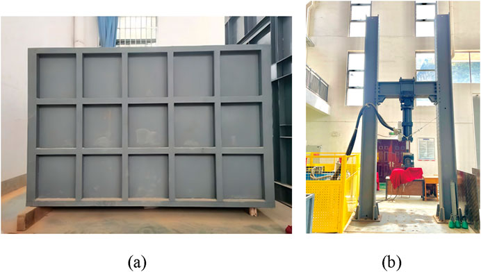
Figure 1. Test equipment. (A) Test chamber, (B) Electro-hydraulic servo fatigue testing machine.
The test fill soil was made of Guilin Lijiang River sand, which was sieved with 2 mm sieve after natural drying and indoor drying, and the effective particle size of sand and soil was obtained by sieving method is d10 = 0.08 mm, the median particle size is d30 = 0.13 mm, and the limiting particle size is d60 = 0.22 mm, and its coefficient of inhomogeneity is Cu = 2.75, and coefficient of curvature is Cc = 0.96, which was poorly graded silt, and the gradation curve was as shown in Figure 2.
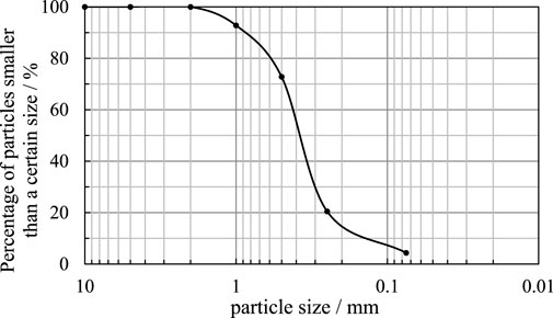
Figure 2. Particle grading curve of test sand.
The filament woven geotextile was selected as the reinforcing material for the test. The total length of the test geotextile reinforcement is 800 mm, the anchorage length on both sides is 300 mm, and the width is 500 mm. Other technical specifications of the geotextile are shown in Table 1 below.

Table 1. Geotextile mechanical properties.
This test simulates the collapse event at a site on Guilin Road, Heping District, Tianjin, with a collapse length of about 3 m, a width of about 1 m, and a depth of about 2 m. Based on similarity theory, the geometrical similarity constant Cl = 5, so the model similarity ratio of 1:5 is selected (Pai and Wu, 2021). The similarity constants for physical quantities such as gravity acceleration, cohesion, and other related parameters are presented in Table 2. The design of geotextiles to prevent karst subgrade collapse was carried out under the condition of 200 mm collapse width, 500-mm fill height and 1.5 times anchorage length. The primary focus of this study was to examine the effects of different reinforced conditions (reinforced, unreinforced) and different loading modes (unloaded, static, dynamic) on the load transfer and sharing of reinforced cushion. Key parameters monitored included vertical stresses in both subsided and stable areas, as well as displacements within the soil and at its surface. The study also analyzed how reinforced and unreinforced conditions affect the subgrade under both static and dynamic loading, with particular attention to the distribution of vertical stresses and vertical displacements. The static load applied was 2.5 kN, while the dynamic load consisted of a sinusoidal wave with an amplitude of 2 kN, a frequency of 5 Hz, and a repetition rate of 1,000 cycles (Gao, 2021).
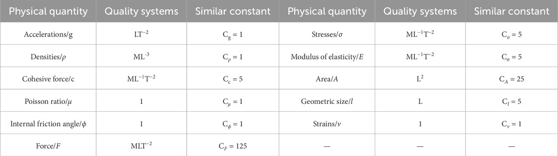
Table 2. Model test similarity constants.
Vertical stresses were monitored by a strain micro-earth pressure box, internal displacements were recorded with MEMS sensors, and surface displacements of the fill were measured with a displacement sensor. The MEMS sensors employ high-performance microprocessors to monitor internal displacement of soil, utilizing dynamic solution algorithms and Kalman filter techniques for data processing (Han et al., 2023). The earth pressure box, displacement sensor, and MEMS sensor were integrated with a strain gauge system and connected to a computer for real-time data acquisition. Data was collected at a frequency of one sample per second through dedicated data acquisition and analysis software. The equipment is shown in Figure 3.
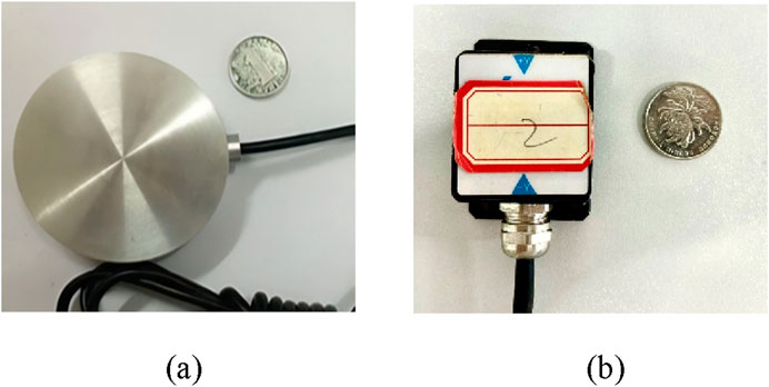
Figure 3. Measurement equipment. (A) Micro earth pressure box, (B) MEMS sensor.
The reinforced and unreinforced conditions in model test are shown in Figure 4. The test simulated the karst collapse process through the lower fall of the movable plate structure in the lower part of the model box. In the reinforced condition, 70 mm of sand was utilized to the soil, followed by the placement of a geotextile measuring 800 mm in length and 500 mm in width. This geotextile was then filled with 30 mm in thick of sand and compacted, resulting in an overall thickness of 60 mm for the reinforced bedding (Zhang et al., 2021). In contrast, under unreinforced test conditions, no geotextile was employed. The monitoring devices were installed in the same position in both cases, with the earth pressure box positioned at 100 mm and the three MEMS sensors installed at 350 mm at positions designated as D4, D3 and D2 to monitor the internal displacement of the soil. After the completion of the fill, three displacement gauges were installed on the fill surface at locations noted as D7, D6 and D5 to monitor subsidence on the fill surface.
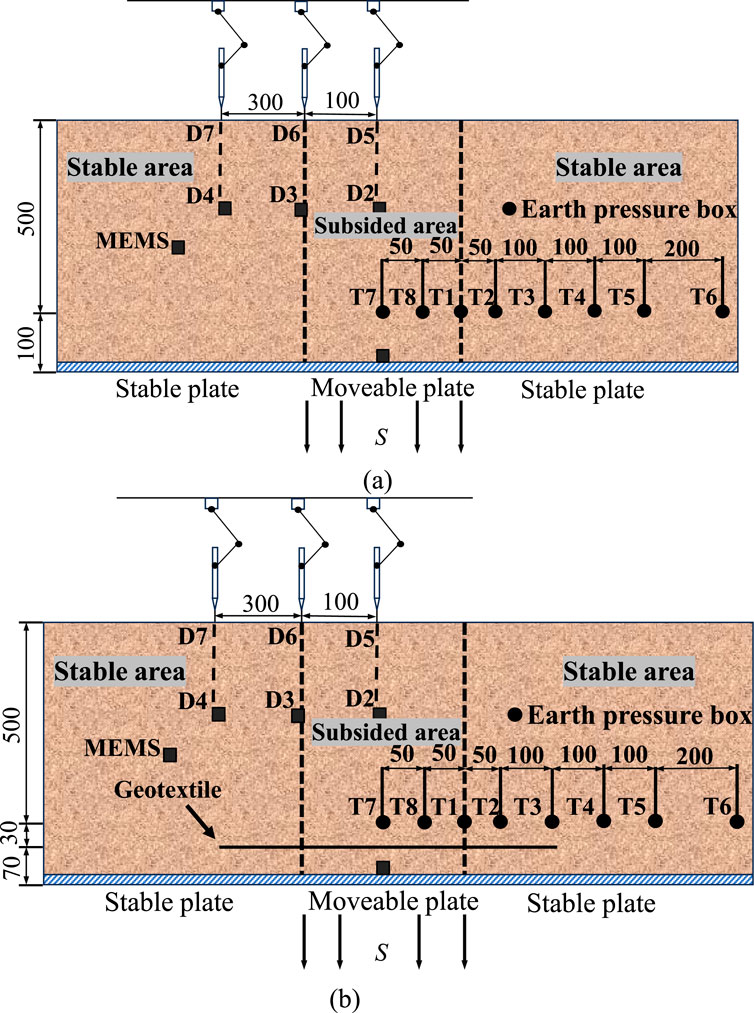
Figure 4. Arrangement of measuring instruments (mm). (A) Unreinforced condition. (B) Reinforcement condition.
Figure 5 demonstrates the vertical stress distribution on the reinforced cushion at the end of subsidence (Chen et al., 2020). The end-of-subsidence phase of the test is defined as the relative subsidence d = subsidence/collapse width*100% = 10%. The vertical stresses of the fill soil in the subsided area and the stable area are not uniformly distributed. Instead, there is a tendency for the center of the subsided area to have a larger vertical stress, while the edges have a smaller vertical stress. As the distance from the collapse center increases, the vertical stress of the fill soil in the stable area initially rises steeply, then declines steeply, and finally levels off. The decrease of vertical stress shows roughly exponential trend.
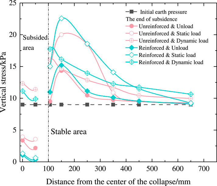
Figure 5. Vertical stress distribution on reinforced cushion.
A comparison of the vertical stress distribution under dynamic and static loading reveals distinct differences. In the subsided area, the vertical stress under dynamic loading is higher than that under static loading, while in the stable area, the vertical stress under static loading is greater. For example, at measurement point T8 in subsided area, the vertical stress is 3.57 kPa under static load and 11.40 kPa under dynamic load, with a difference of 68.68%. Conversely, at point T2 in the stable area, the maximum vertical stress under static loading is 20 kPa, while under dynamic loading, it is 16.06 kPa at point T1, showing a 19.7% difference. This discrepancy can be attributed to the shorter application time of dynamic loads compared to static loads, which results in a more immediate impact. Additionally, dynamic loading exacerbates the instability of the fill, causing adjacent soil particles to shift towards the subsided area. Consequently, dynamic loading exerts a more pronounced weakening effect on the geotechnical arch mechanism in the collapse zone than static loading.
The variation in vertical stress with subsidence at locations T7 and T8 in the subsided areas, and T1 and T2 in the stable areas under unreinforced conditions is shown in Figure 6. In the figure, the grey squares represent the initial earth pressure, the pink solid circles indicate the unloaded condition, the hollow circles correspond to static loading, and the central crosses denote dynamic loading. As seen in Figures 6A, B, the vertical stresses at positions T7 and T8 in static load and unload conditions initially decrease during the early stages of subsidence, falling below the initial earth pressure. In contrast, under dynamic loading, the vertical stresses at these locations exceed the initial earth pressure. For example, at measurement point T7, the initial earth pressure was 9 kPa. At the onset of subsidence, the vertical stress decreased to 3.37 kPa under the unloaded condition, 3.93 kPa under static loading, and increased to 12.34 kPa under dynamic loading. This behavior can be attributed to the interaction between the fill at the edge of the subsided area and the stable fill on both sides. During subsidence, part of the vertical stress is transferred into friction with the edges. Additionally, the primary stress within the fill is redirected due to the constraints imposed by the edges, resulting in a more significant reduction in earth pressure near the edge compared to the center of the subsidence area (Chen et al., 2019).
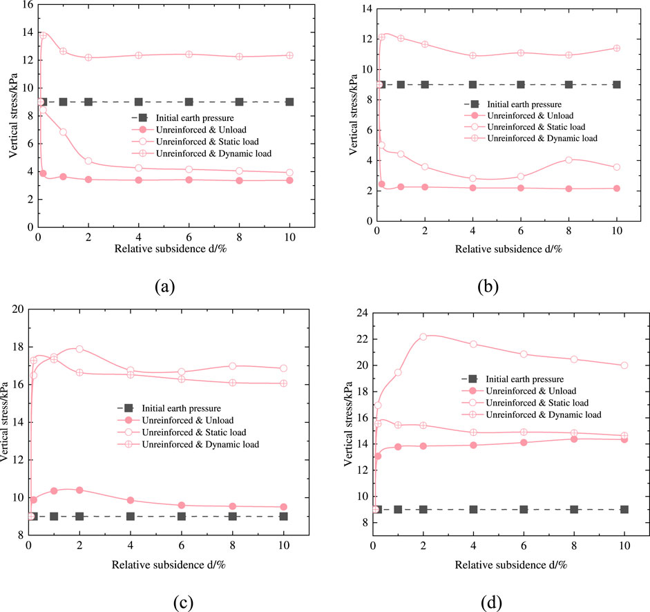
Figure 6. Vertical stresses in unreinforced condition. (A) Position T7 (B) Position T8 (C) Position T1 (D) Position T2.
From Figures 6C, D, the vertical stresses at T1 and T2 in the stable area are greater than the initial earth pressure, with vertical stresses under static loading being greater than those under dynamic loading. Take T1 as an example, its initial earth pressure is 9 kPa, the vertical stress rises to 10.39 kPa and then slowly decreases to 9.50 kPa under unloaded condition, first rises to 17.88 kPa and then decreases to 16.86 kPa under static loaded condition, and rises to 17.33 kPa and then slowly decreases to 16.06 kPa under dynamic loaded condition. These observations indicate that, under static loading, the soil arch effect rapidly distributes the load from the onset of loading, enhancing load transfer. In contrast, under dynamic loading, the soil arch effect is weakened, preventing effective load sharing, including the self-weight of the fill. As a result, the vertical stress under dynamic loading initially increases and then decreases. Additionally, the primary locations of load transfer differ between static and dynamic loading conditions.
Figure 7 presents the vertical stress curves of the subsided areas T7 and T8 and the stable areas T1 and T2 with relative subsidence under the reinforced condition at the end of subsidence. Under the reinforced condition, the vertical stress change curves of each position in the subsided area and stable area have basically the same trend as that of the vertical stress curve in the unreinforced condition. In the subsided area, for example, at point T7, the vertical stresses under unload, static, and dynamic load are 1.06kPa, 1.31kPa, and 11.14kPa, respectively. The reductions in vertical stress without reinforcement for the three loading scenarios is 68.55%, 69.21% and 9.72% respectively. In the stable area, for example, at point T1, the vertical stresses under unload, static load, and dynamic load are 10.98kPa, 18.02kPa, and 17.74kPa, respectively. The vertical stresses increased by 15.09%, 6.88% and 10.46% respectively.
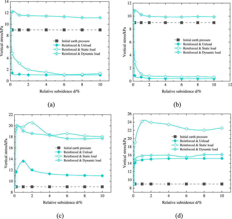
Figure 7. Vertical stresses under reinforced condition. (A) Position T7 (B) Position T8 (C) Position T1 (D) Position T2.
By analyzing Figures 6, 7, it is evident that under unloaded and static loading conditions, load sharing and transfer in the stable area primarily occur at location T2. However, the introduction of dynamic loading disrupts this balance. Under dynamic loading, the soil arch effect is weakened, and the tensile membrane effect comes into play, causing the load transfer in the stable area to shift from T2 to T1. Additionally, when considering the impact of reinforcement, a significant change in the vertical stress distribution is observed. Under the reinforced condition, the vertical stresses at T7 and T8 in the subsided area are smaller than those in the unreinforced condition, and the vertical stresses at T1 and T2 in the stable area are larger than those in the unreinforced condition, which indicates that the reinforcement of geotextiles can reduce the load on the unstable soil in the subsided area and enhance the stability of the soil. Furthermore, the tensile membrane effect facilitates effective load transfer to the stable area.
Figure 8 illustrates the vertical displacements of the fill surface and the midsection of the fill under various reinforcement conditions and loading scenarios at the end of subsidence (relative subsidence d = 10%). As shown in Figure 8, at the end of subsidence, the vertical displacement of the fill soil within the subsided area and the fill soil in the stable area near a certain range of the subsided area is larger, the vertical displacement of the fill soil in other areas of the stable area is obviously reduced, and the vertical displacement of the fill soil without loading and under static loading is nearly zero.
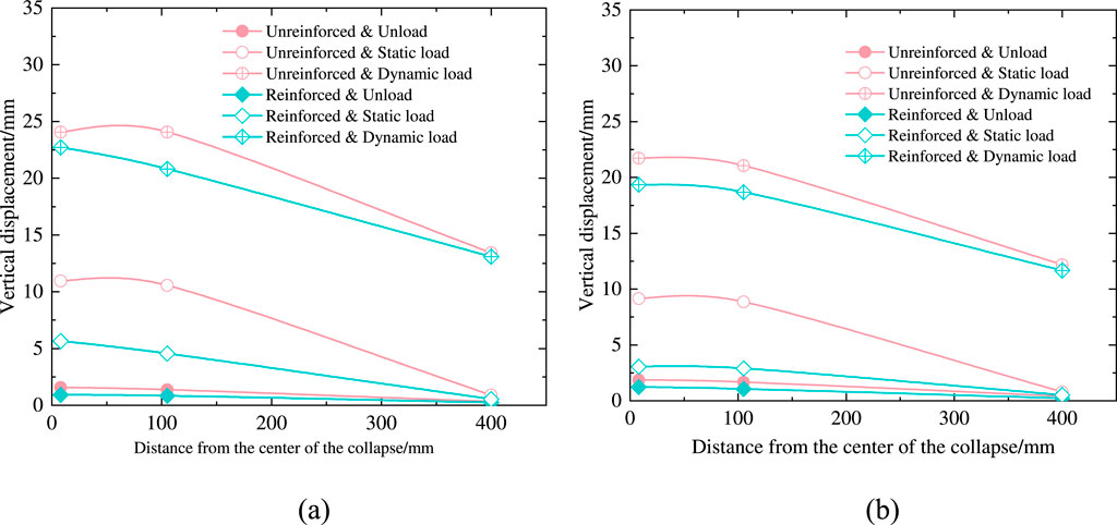
Figure 8. Vertical displacements at different fill heights. (A) Vertical displacement of soil surface (B) Vertical displacement in the middle of the soil.
Under unloaded condition, the vertical displacement of the soil under the unreinforced and reinforced conditions exhibits a trend where the displacement is larger at the midsection of the soil compared to the surface. Furthermore, the displacement increases with decreasing height within the soil. Under both static and dynamic loading conditions, the vertical displacement of the soil, for both unreinforced and reinforced conditions, is greater at the surface than at the midsection, indicating that the loads are primarily applied to the soil surface. The vertical displacement of the fill soil under loading is most pronounced at the surface and in the surrounding areas of the applied load, with dynamic loading resulting in notably higher displacements compared to static loading. Additionally, it is evident that the geotextile-reinforced cushion significantly restricts vertical displacement. Compared to the unreinforced condition, the vertical displacement at all measured locations is substantially reduced under the reinforced condition.
Figure 9 shows the vertical displacement of the fill at the surface and the center of the fill soil under different loading conditions. The vertical displacement is greatest under dynamic loading, followed by static loading, with the smallest displacement observed under unloaded conditions. In the relative subsidence range of 0%–1%, the vertical displacement at each measurement point increases approximately linearly with relative subsidence. In the 1%–10% relative subsidence range, the vertical displacement under dynamic loading continues to increase roughly linearly with subsidence, though at different rates. Conversely, under both unloaded and static loading conditions, the vertical displacement increases with subsidence, but the change is less pronounced. The vertical displacement of D2 is measured at 24.07 mm in the case of an unreinforced-dynamic load, and 22.73 mm in the case of a reinforced-dynamic load, exhibiting a reduction ratio of 5.58%. The vertical displacement of D5 is 21.73 mm in the case of unreinforced-dynamic load and 19.35 mm in the case of reinforced-dynamic load, resulting in a reduction ratio of 10.95%. It is evident that soil damage is more severe under dynamic load conditions and geotextile reinforcement can also reduce the vertical displacement of the soil. Compared with the unloaded and static load case, the reduction in vertical displacement is not as apparent. The vertical displacement of the soil under the reinforced condition is smaller than that under the unreinforced condition in difference load conditions, indicating that the reinforcement of geotextiles can effectively limit the soil and reduce the vertical displacement of the soil.
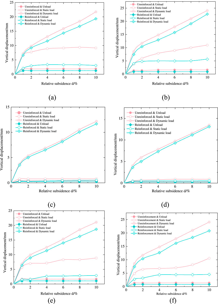
Figure 9. Vertical displacements of the fill surface and the location of each measurement point in the center. (A) Position D2 (B) Position D5 (C) Position D4 (D) Position D7 (E) Position D3 (F) Position D6.
In order to quantify the load transfer efficiency by the soil arch effect and the tensile membrane effect, the load transfer efficiency is introduced, which is obtained by the ratio of the load increment in the stable area to the initial earth pressure (Wu et al., 2021), as shown in Equation 1.
where σ0 denotes the vertical stress (kPa) at each location in the stable area and σ denotes the initial earth pressure (kPa).
The load transfer efficiencies obtained from the calculation of the vertical stresses at the beginning of subsidence (0.2% relative subsidence) and the end of subsidence (10% relative subsidence) phases in the selected stable areas T1 and T2 locations are shown in Table 3.

Table 3. Load sharing and transfer efficiency in the stable area under different conditions.
As shown in Table 3, the load sharing and transfer efficiency under reinforced conditions is higher than that under unreinforced conditions. The maximum efficiency is observed under the reinforced-static loading condition, with a value of 150.89%, while the minimum efficiency occurs under the unreinforced-unloaded condition, at 5.56%.
Under unreinforced conditions, the load transfer efficiency is solely attributed to the soil arch effect. In contrast, under reinforced conditions, the load transfer efficiency consists of two components: the soil arch effect and the tensile membrane effect. When disregarding the limiting influence of geotextile reinforcement on the soil arch effect, the load transfer efficiency due to the tensile membrane effect is represented by Equation 2 (Van Eekelen et al., 2013).
Where n is the load transfer efficiency under reinforced condition, nT is the soil arch effect load transfer efficiency under reinforced condition and nL is the membrane effect load transfer efficiency.
Table 4 presents a comparison of the load sharing effect of the soil arch effect and the load transfer efficiency of the tensile membrane effect. As shown in Table 4, the load sharing efficiency of soil arch effect is basically greater than the load transfer efficiency of fabric tensile membrane effect, which indicates that the load sharing and transfer mainly rely on the stress redistribution under the action of soil arch effect, and the tensile membrane effect of fabric also plays its role in load transfer, but it is much smaller than that of soil arch effect.
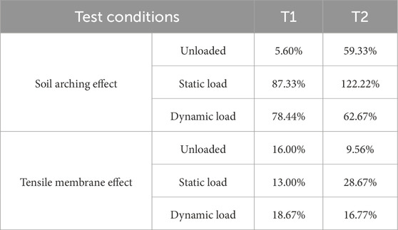
Table 4. Load sharing and transfer efficiency of soil arching effect and tensile membrane effect.
Based on a practical case study of a subgrade collapse project, six model test schemes were designed to investigate the load transfer and sharing performance of reinforced cushions under various reinforcement and loading conditions. The main conclusions are as follows.
(1) During the subsidence process, vertical stresses in the subsided area decrease, while those in the stable area increase. The load applied influences the soil arch effect, with dynamic loads having a more significant impact on soil stability in the subsided area compared to unloaded and static loading conditions. It is recommended to use higher reinforcement strengths in karst areas subjected to dynamic loads.
(2) The synergy between the soil arch effect and the tensile membrane effect, resulting from geotextile reinforcement, leads to a reduction in vertical soil displacement. Under dynamic loading, vertical displacement is reduced by 5.58%–10.95%, while under unloaded and static loading conditions, displacement is reduced by 34.76%–66.56%. These findings demonstrate that geotextiles are highly effective in treating karst subsidence when the anchorage length is 1.5 times the width of the subsided area.
(3) This study provides both theoretical insights and experimental data to support the design of geotextile reinforcement in karst subsided areas, contributing to the effective prevention of karst collapse.
The original contributions presented in the study are included in the article/supplementary material, further inquiries can be directed to the corresponding authors.
DW: Conceptualization, Investigation, Methodology, Writing–original draft, Writing–review and editing. YYi: Formal Analysis, Software, Writing–original draft, Writing–review and editing. QC: Data curation, Investigation, Software, Writing–original draft, Writing–review and editing. JnW: Formal Analysis, Investigation, Project administration, Writing–review and editing. YYa: Methodology, Writing–review and editing. JaW: Data curation, Formal Analysis, Investigation, Methodology, Writing–review and editing. RA: Software, Supervision, Writing–review and editing.
The author(s) declare that financial support was received for the research, authorship, and/or publication of this article. Financial support for this work is gratefully acknowledged from the Natural Science Foundation of China Grant No. 42067044 and Guangxi Science and Technology Major Program Grant No. AB23026028. All the supports are greatly appreciated.
The authors declare that the research was conducted in the absence of any commercial or financial relationships that could be construed as a potential conflict of interest.
The author(s) declare that no Generative AI was used in the creation of this manuscript.
All claims expressed in this article are solely those of the authors and do not necessarily represent those of their affiliated organizations, or those of the publisher, the editors and the reviewers. Any product that may be evaluated in this article, or claim that may be made by its manufacturer, is not guaranteed or endorsed by the publisher.
Al Heib, M., Hassoun, M., Emeriault, F., Villard, P., and Farhat, A. (2021). Predicting subsidence of cohesive and granular soil layers reinforced by geosynthetic. Environ. Earth Sci. 80, 70. doi:10.1007/s12665-020-09350-3
Baryakh, A. A., and Fedoseev, A. K. (2011). Sinkhole Formation mechanism. Joumal Min. Sci. 47 (4), 404–412. doi:10.1134/S1062739147040022
Bi, Z., Gong, Q., Zhou, S., and Cheng, X. (2020). Experimental study of the evolution law of vertical soil arch under cyclic loading. Rock Soil Mech. 41 (03), 886–894+932. doi:10.16285/jrsm.2019.0483
Chen, F., Lin, Y., and Chen, S. (2020). Analytical solutions for geosynthetic-reinforced cohesive subgrade spanning trench voids. Geotext. Geomembranes 48 (6), 854–866. doi:10.1016/j.geotexmem.2020.06.004
Chen, Q., Guo, S., Xu, C., Liang, L., and Liu, X. (2019). Trapdoor model tests on loosening earth pressure and failure mode of loosening zone in sand. J. Central South Univ. Sci. Technol. 50 (01), 108–117. doi:10.11817/i.issn.1672-7207.2019.01.015
Eskişar, T., Otani, J., and Hironaka, J. (2012). Visualization of soil arching on reinforced embankment with rigid pile foundation using X-ray CT. Geotext. Geomembranes 46 (5), 611–624. doi:10.1016/i.geotexmem.2011.12.002
Gao, C. (2021). Model tests of road subsidence progress with underground cavities caused by cyclic dynamic load. Hydrogeology Eng. Geol. 48 (01), 70–77. doi:10.16030/j.cnki.issn.1000-3665.202003002
Gao, X., Li, Z., Lin, J., Song, Y., Qing, S., Cui, X., et al. (2023). Grouting technology for surface soft soil in coastal tidal karst area and its application. J. Zhejiang Univ. Eng. Sci. 57 (03), 552–561. doi:10.3785/i.issn.1008-973X.2023.03.013
Guo, L., Wang, S., Sun, L., Kang, Z., and Zhao, C. (2020). Numerical simulation and experimental studies of karst caves collapse mechanism in fractured-vuggy reservoirs. Geofluids 2020, 1–21. doi:10.1155/2020/8817104
Han, S., Ni, C., and Lu, J. (2023). An optimal estimation approach for MEMS INS performance improvements based on single-FOG monitoring. IEEE Sensors J. 23, 7199–7206. doi:10.1109/JSEN.2023.3242962
Hou, J., Chu, C., Li, J., Copeland, T., Chen, J., and Nam, B. H. (2024). An analytical model of horizontal-vertical geogrid reinforced foundation. Ksce J. Civ. Eng. 28 (7), 2673–2680. doi:10.1007/s12205-024-0354-7
Islam, N., Linrong, X., Usman, A. B., Raza, B., Yongwei, L., and Shengxiang, L. (2024). Study on field and numerical analysis of karst collapse as railway hazard. Proc. Institution Civ. Eng. - Geotechnical Eng., 1–15. doi:10.1680/jgeen.24.00242
Jiang, H., Bian, X., Chen, Y., and Jiang, J. (2015). Full-scale accelerated testing for simulation of train moving loads in track-subgrade system of high-speed railways. China Civ. Eng. J. 48, 85–95. doi:10.15951/j.tmgcxb.2015.09.010
Jiang, X., Dai, J., Zheng, Z., Li, X. J., Ma, X., Zhou, W., et al. (2024). An overview on karst collapse mechanism in China. Carbonates Evaporites 39, 71. doi:10.1007/s13146-024-00986-x
Li, P., Wu, J., Zhou, W., and LaMoreaux, J. W. (2023). Karst collapse and its management. Hazard Hydrogeol., 105–141. doi:10.1007/978-3-031-48427-8_5
Pai, L., and Wu, H. (2021). Shaking table test study on dynamic responses of underpass tunnels under earthquake. Chin. J. Rock Mech. Eng. 40 (01), 88–100. doi:10.13722/j.cnki.jrme.2020.0353
Pham, M. T., Briancon, L., Dias, D., and Abdelouhab, A. (2018). Investigation of load transfer mechanisms in granular platforms reinforced by geosynthetics above cavities. Geotext. Geomembranes 46 (5), 611–624. doi:10.1016/j.geotexmem.2018.04.015
Rui, R., Zhai, Y., Xu, Y., and He, Q. (2021). Experimental investigations on influences of ground loss on earth pressure and settlement of adiecent underground retaining structures. Chin. J. Geotechnical Eng. 43 (04), 644–652. doi:10.11779/CJGE202104006
Shi, H., Li, Q., Zhang, Q., Yu, Y., Xing, Y., and Yu, K. (2019). Mechanism of shallow soil cave-type karst collapse induced by water inrush in underground engineering construction. J. Perform. Constr. Facil. 34 (1), 04019091. doi:10.1061/(asce)cf.1943-5509.0001353
Van Eekelen, S. J. M., Bezuijen, A., and Van Tol, A. F. (2013). An analytical model for arching in piled embankments. Geotext. Geomembranes 39, 78–102. doi:10.1016/j.geotexmem.2013.07.005
Villard, P., and Laurent, B. (2008). Design of geosynthetic reinforcements for platforms subjected to localized sinkholes. Can. Geotechnical J. 45 (02), 196–209. doi:10.1139/T07-083
Wang, X., Wang, S., Peng, X., Ma, T., and Chen, B. (2022). Equivalent numerical simulation method and application in karst-induced collapse of overlying sandy stratum. Eng. Fail. Anal. 137, 106280. doi:10.1016/j.engfailanal.2022.106280
Wen, H., Fang, Z., Tan, F., Qi, X., Zeng, H., and Tao, L. (2025). Disaster mechanisms of hourglass-type karst ground collapse. Carbonates Evaporites 40, 5. doi:10.1007/s13146-024-01041-5
Wu, D., Liang, Y., Yang, Y., and Wu, J. (2022a). Study of the subsidence width influence on the geotextile control of a subgrade collapse based on a half-symmetric model test. Appl. Sciences-Basel 12 (19), 9504. doi:10.3390/app12199504
Wu, D., Luo, C., Li, Y., Yang, Y., Liang, Y., and Wu, J. (2021). Application of a geotextile in the treatment of post-subsidence in karst areas. Appl. Sci. 11, 11826. doi:10.3390/app112411826
Wu, Y., Zhao, Y., Gong, Q., Zornberg, J. G., Zhou, S., and Wang, B. (2022b). Alternant active and passive trapdoor problem: from experimental investigation to mathematical modeling. Acta Geotech. 17 (7), 2971–2994. doi:10.1007/s11440-021-01426-Z
Yao, Y., Li, A., Zhou, B., Xiao, Z., and Chu, Y. (2023). Analysis on Key technologies of high - speed railway subgrade in karst foundation. J. Of Railw. Eng. Soc. 40 (08), 35–39. doi:10.16285/j.rsm.2021.0352
Yin, H., Shi, Y., Niu, H., Ma, C., Liu, G., Zhai, P., et al. (2018). Characteristics, detection, and prevention of karst sinkholes: a case study in Laiwu iron ore mine areas, Shandong Province, China. Environ. Earth Sci. 77, 136. doi:10.1007/s12665-018-7310-0
Zhang, L., Ou, Q., Zhao, M., Ding, X., and Liu, J. (2021). Numerical analysis on dynamic response characteristics of geosynthetic reinforced embankment under moving load. Rock Soil Mech. 42 (10), 2865–2874. doi:10.16285/jrsm.2021.0352
Zheng, G., Xia, B., Zhou, H., Yu, X., and Diao, Y. (2023). Influence of deep-cement-mixing column rows on the performance of geosynthetics-reinforced column-supported railway embankment. Transp. Geotech. 41, 101012. doi:10.1016/j.trgeo.2023.101012
Keywords: karst subgrade collapse, geotextiles, mode tests, static and dynamic loading, earth pressure
Citation: Wu D, Yi Y, Chen Q, Wu J, Yang Y, Wu J and Amin R (2025) Experimental study of geotextiles for karst subgrade collapse under static and dynamic loads. Front. Earth Sci. 13:1523076. doi: 10.3389/feart.2025.1523076
Received: 05 November 2024; Accepted: 27 January 2025;
Published: 19 February 2025.
Edited by:
Qi Yao, China Earthquake Administration, ChinaReviewed by:
Luyuan Huang, China Earthquake Administration, ChinaCopyright © 2025 Wu, Yi, Chen, Wu, Yang, Wu and Amin. This is an open-access article distributed under the terms of the Creative Commons Attribution License (CC BY). The use, distribution or reproduction in other forums is permitted, provided the original author(s) and the copyright owner(s) are credited and that the original publication in this journal is cited, in accordance with accepted academic practice. No use, distribution or reproduction is permitted which does not comply with these terms.
*Correspondence: Jing Wu, YmFpaHVhMjEyQDE2My5jb20=; Yanxin Yang, eWFueGlueWFuZ3N3anR1QGZveG1haWwuY29t
Disclaimer: All claims expressed in this article are solely those of the authors and do not necessarily represent those of their affiliated organizations, or those of the publisher, the editors and the reviewers. Any product that may be evaluated in this article or claim that may be made by its manufacturer is not guaranteed or endorsed by the publisher.
Research integrity at Frontiers
Learn more about the work of our research integrity team to safeguard the quality of each article we publish.