 Jiang Zhao1,2
 Wen-Ling Tian
 Sheng-Qi Yang
94% of researchers rate our articles as excellent or good
Learn more about the work of our research integrity team to safeguard the quality of each article we publish.
Find out more
ORIGINAL RESEARCH article
Front. Earth Sci., 16 April 2025
Sec. Solid Earth Geophysics
Volume 13 - 2025 | https://doi.org/10.3389/feart.2025.1477727
This article is part of the Research TopicExperimental and Numerical Simulations of Rock PhysicsView all 18 articles
To explore the deformation and failure mechanism of multi-arch tunnel without a middle pilot tunnel, taking the Sanyanjing tunnel of Qiuyan Expressway in Yunnan province as the research object. The stress evolution and the associated deformation and failure mechanisms of the surrounding rock, composed of class IV limestone, were studied using a physical model test during the excavation process. The results show that tangential stress attenuation occurs within a distance equal to the diameter of the tunnel wall, while stress concentration occurs beyond this range in the unsupported tunnel. However, the supporting structure, forms a stable pressure arch within the surrounding rock, which makes the elastic zone extend to the surrounding and deep of the tunnel. The surrounding rock at the top of the middle wall in the unsupported tunnel shows the trend of linear decrease of horizontal stress and rapid linear increase of vertical stress. Meanwhile, vertical stress remains relatively stable, whereas horizontal stress exhibits a pronounced “bias effect.” The tunnel invert and the outer arch foot are identified as vulnerable structural components, necessitating close attention to lining strength and construction quality.
•◆ The evolution process of radial stress and tangential stress of surrounding rock of tunnel during excavation is analyzed, and the influence of lining on the stability of surrounding rock during the construction of multi-arch tunnel without a middle pilot tunnel is revealed.
•◆ The strain field of surrounding rock in physical model test was obtained by using XTDIC three-dimensional digital speckle full-field strain measurement and analysis system.
A type of highly efficient tunnel, double-connected arch tunnel, is widely used in mountainous road projects, urban expressways, and engineering projects that require saving land and optimizing the layout of routes in China (Wu et al., 2020; Liu et al., 2022). At present, the middle pilot tunnel method is used mostly in the construction of double-arch tunnels (Ambika and Neelima, 2020), as shown in Figure 1a. Due to the steel arch, the position of the shared middle wall have twice the bias action, which laid the groundwork for the secondary ling cracking of the double-arch tunnel (Zhang et al., 2019), thus the method without a middle pilot tunnel was proposed (Min, et al., 2020; Sui et al., 2021), as shown in Figure 1b. Compared with the traditional tunnel with middle pilot and the three-tunnel method, this method has the advantages of high construction efficiency, low cost, environmental friendliness, and strong safety (Tang et al., 2022).
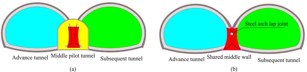
Figure 1. Two construction methods for double-connected arch tunnels. (a) Conventional double-arch tunnel. (b) Double-arch tunnel without a middle pilot tunnel (Jiang et al., 2021).
The construction technology without pilot tunnel represents a development trend in the construction of multi-arch tunnel, and the construction technology has gradually matured (Bi et al., 2024). It is used in the construction of some tunnels such as the Baiyun Mountain double-arch tunnel, Beijing Tianwaitian underground shopping mall, Huangyan high-speed Yangquangou Tunnel (Jian et al., 2024). When this kind of tunnel structure is adopted, the rock and soil body in the upper part of one tunnel is excavated firstly, and then the lower rock and soil excavation is carried out near the middle partition wall, and the rock and soil excavation in the middle partition wall area is completed simultaneously. Then the temporary support is arranged, followed by the casting of the partition wall is carried out. After the completion of the middle partition wall, the other side of the tunnel will be excavated, and the temporary support structure will be removed in time. The core of non-center pilot tunnel construction is to use appropriate temporary support methods to ensure the stability of the middle partition wall in the construction process. Therefore, in the face of different strata and geological conditions, it is usually required to use a variety of pre-strengthening technical methods such as advanced small conduit and advanced anchor rod to stabilize (Zeng et al., 2019).
Physical model tests in a laboratory using a small-scale model are a common method to investigate the stability of large-scale geotechnical engineering, which is an intuitive and efficient research method (Xiao et al., 2005; Meguid et al., 2008; Wang et al., 2023). Physical model testing originated in Italy in the 1960s, then Heuer and Hendron et al. (1971) selected an underground cavern as the research entity and conducted a series of model tests to discuss the excavation process under static load, focusing on the changes of the mechanical properties of the surrounding rock of the underground cavern with time under different conditions with or without lining structure and with different rock integrity (including intact rock mass and fractured rock mass). Fumagalli conducted an in-depth study of the Vajont arch dam through a series of model tests, covering from the elastic response of materials to plastic deformation to the ultimate failure of the structure (Fumagalli, 1979; Sterpi and Cividini, 2004 conducted a series of physical simulation experiments on shallow-buried tunnels under soft soil layers, supplemented by two-dimensional and three-dimensional finite element numerical simulation analysis. Based on a series of tunnel physical model experiments carried out in the environment of soft soil layer, Meguid et al. (2008) conducted an in-depth discussion on the deformation and fracture mechanism of soft soil induced during tunnel excavation. Xie et al. (2022) conducted model tests and numerical simulations to study the time-varying response regularity of surrounding rock construction mechanics in a double-arch tunnel without a middle pilot tunnel.
After years of research, Chinese scholars have made a series of achievements in the field of physical model test (Li et al., 2016; Liu et al., 2006; Lin et al., 2021, 2024). Since 1973, team of Gu has carried out model test research on anchor support and reinforcement mechanism research on prestressed anchor cable with underground caverns. It is the first in China to propose and successfully implement the test scheme of tunnel model under plane strain conditions and the innovative test scheme of “loading first, excavating later”. This greatly enhanced the consistency of model test results with real engineering situations, and thus achieved a series of important academic achievements (Gu et al., 1994). Based on the engineering background of Baziling bifurcated tunnel, Li and Zhang et al. (2007) conducted a series of large-scale physical model tests for the transition from small arch section to large arch section and from multiple arch section to small clear distance section, and deeply explored the law of stress and displacement variation around the bifurcated tunnel, as well as the failure mechanism of surrounding rock of the bifurcated tunnel. Li et al. (2012) relying on the Changcheng multi-arch tunnel project as the engineering background, focused on the changes in the mechanical characteristics of the surrounding rock during the construction of the extremely shallow buried multi-arch tunnel, and used physical model test methods to simulate the tunnel excavation process. He et al. (2018) made an in-depth analysis of the mechanical properties and failure processes of the surrounding rock and lining of the asymmetric multi-arch tunnel under different load conditions by using a large-scale experimental device. Li et al. (2021) set up a large three-dimensional physical model of the Letuan tunnel in Binlai high-speed, and conducted an overload test on the ultra-large tunnel, and studied its stress and displacement changes and the overall stability of surrounding rock. Jiang et al. (2021) designed a large-scale shaking model with 1:20 scale to study the dynamic characteristics of double-arch tunnel slope under earthquake action.
In recent years, many scholars have carried out numerous model tests of multi-arch tunnels relying on various large-scale loading equipment and new measurement technologies. Most of these studies adopt the middle pilot tunnel method, where the tunnel structure is primarily characterized by an integral middle wall and a compound middle wall. However, there has been relatively little systematic research on model tests of multi-arch tunnels without a middle pilot tunnel. Therefore, a physical model test and XTDIC three-dimensional digital speckle full-field strain measurement and analysis system were used to explore the stress evolution and the associated deformation and failure mechanisms of the surrounding rock, and the vulnerable structural components can be identified, which provided theoretical support for similar projects.
The Sanyanjing tunnel, located at 1.5 km north of Nuoyi Village, Yanshan, is part of the 3rd section of Yunnan Qiuyan Expressway. The maximum buried depth of the tunnel is 64 m. The surrounding rock of this tunnel area is dominated by red clay and medium-weathered limestone, with weak to medium water richness. The length of the Ⅳ level surrounding rock section accounts for 55% of the tunnel length (210 m), as shown in Figure 2a. The tunnel is designed as a multi-arch tunnel without a middle pilot tunnel, and the cross-section of the tunnel lining is shown in Figure 2b.
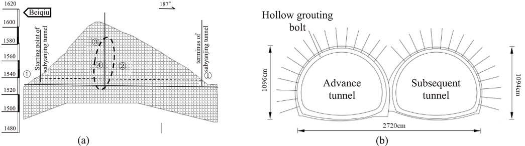
Figure 2. The (a) longitudinal section diagram and (b) Cross section diagram of the Sanyanjing tunnel.
The key of a geotechnical model tests depends on whether it can be based on engineering and geological conditions and the three fundamental theorems of similarity (Lin et al., 2020), ensuring that the prototype and model systems achieve mechanical similarity within the elastic range. In practical operation, although it is necessary to meet the requirements of the equilibrium equation, geometric equation, physical equation, boundary conditions, and compatibility conditions, the limitations of the experimental equipment scale and the complexity and variability of geological conditions and stress environments often make it difficult to ensure all the mechanical parameters of similar materials satisfied the requirements of the similarity ratio. Based on previous research, geotechnical prototype and model can achieve most of the experimental objectives by satisfying the similarity of stress and geometry, and the Equation 1 needs to be satisfied:
where, P represents the external load on the rock mass, MPa; E represents the elastic modulus of rock, GPa; L represents the geometric size of the tunnel, m; R represents the strength of the surrounding rock, MPa; σ represents the stress of the surrounding rock, MPa; ε represents the deformation of the surrounding rock; γ represents the material weight of the surrounding rock, kN/m3; δ represents the deformation of the surrounding rock, m; and μ represents the Poisson’s ratio of the surrounding rock.
Considering the test equipment and tunnel size, the test similarity ratio was determined: the geometric similarity ratio is 70, the material weight similarity ratio is 1.2, and the similarity ratios of the tensile strength, elastic modulus and uniaxial compression is 84. According to the physical and mechanical parameters of limestone in the engineering geological exploration report, the parameters of the surrounding rock and similar materials are compared as shown in Table 1.
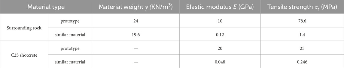
Table 1. Mechanical parameters of prototype surrounding rock and model similar materials.
The vertical principal stress (
Then, the vertical principal stress (
where,
At present, many scholars have conducted relevant studies on limestone similar materials. However, due to different grades and qualities of cementing materials, as well as differences in particle size and grading of aggregates, direct use of the existing ratio may lead to large test errors. According to the mechanical properties of the limestone with high hardness and brittleness, and as close as possible to the geological environment of the original rock, and referring to the research results of model test on similar materials by Wu et al. (2013), the similar materials were determined. The similar materials for surrounding rock were prepared using 325-grade composite Portland cement and building gypsum as cement, and river sand with particle size less than 2 mm as aggregate. Based on the results of similar materials under uniaxial compression, as shown in Figure 2, the elastic modulus increases from 95.5 MPa to 235.26 MPa, and peak strength increases from 1.03 MPa to 2.52 MPa with increasing cement content. The group of similar materials that best meets the requirements has a mass ratio of river sand, gypsum, cement and water is 100:6:9:11.5. The main consideration of the bolt is to meet the geometric similarity requirements while allowing some deviation in stiffness similarity. Therefore, aluminum wire with a diameter of 2 mm and a length of 43 mm was used to simulate the bolt body, and iron sheet with a size of 10 mm × 10 mm was used to simulate the bolt tray, as shown in Figure 3a. Referring to the research of model tests of multi-arch tunnel by Tian et al. (2013), the initial tunnel support was constituted by water, gypsum and barite powder, and the mass ratio of them is 0.65:1:0.06.
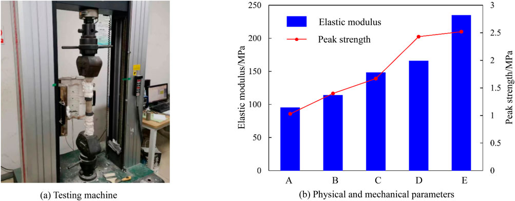
Figure 3. Results of similar materials for the surrounding rock under uniaxial compression. (a) Testing machine (b) Physical and mechanical parameters.
Given the challenge of simultaneously employing excavation and support methods to simulate the construction of a multi-arch tunnel without a middle pilot tunnel, this experiment utilizes the internal mold casting technique to create the tunnel support structure. Additionally, anchor bolts are strategically placed at corresponding positions, and after being positioned at their designated burial points using the embedment method, the rock mass material is cast together. The production process of the shotcrete anchor supporting structure primarily involves utilizing a high-strength foam board to create a mold, pre-arranging the anchor bolt in its designated position, and subsequently pouring layers of evenly mixed gypsum mixture into the mold. Each layer is vibration on a shaking table to ensure material consistency. Following a 2-day curing period following the pouring, the resulting shotcrete anchor supporting structure, formed by releasing the mold is depicted in Figure 4b. Before the test, the left and right apertures were joined together using a gypsum mixture in the same proportions to create a cohesive structure, thereby simulating the overlapping effect between the advanced tunnel and the subsequent tunnel.
Figure 4. Similar material for the support material. (a) anchor bolt, (b) Spray anchor support structure.
The monitoring system is composed of strain bricks, static strain data acquisition instruments and digital photographic measurement system. The static strain acquisition system (Figure 5) includes a strain brick and a static strain data acquisition instrument. Polyurethane was selected as the matrix of strain brick, cut into a cube with a side length of 15 mm. Two resistance strain gauges (BF120-5AA) were pasted in the center of any surface to form a 90° strain flower, and the surface was coated with silicone rubber for protection. By connecting the strain gauge with the static strain data acquisition instrument, the horizontal and vertical strain values of the measuring points in the surrounding rock during tunnel excavation can be monitored, and the horizontal and vertical stresses of the measuring points can be calculated according to the elastic mechanics equation:
where,
Figure 5. Static strain acquisition system, which can be monitored the stress variation during loading process. (a) strain brick, (b) DH3818 strain data acquisition instrument.
According to the size of the model box and the purpose of the experiment, 27 strain gauges were arranged. Of these 4 were arranged in the crown, waist, and inverted arch of the tunnel in the same manner, and 3 were arranged at the top of the intercalation, enabling the monitoring of the strain state of the surrounding rock within twice the diameter of the tunnel. The position of the measurement points is shown in Figure 6, where A-F represent the 6 strain measurement zones on both sides of the tunnel, and 4 measurement points are arranged at increasing distances from the tunnel wall in each measurement zone.
Figure 6. Schematic diagram of measurement point layout (unit: millimeters).
The digital photogrammetry method is widely used in the study of rock deformation and destruction. The XTDIC three-dimensional digital speckle field strain measurement and analysis system (Figure 7) was used to analyses the strain and displacement of the tunnel surface, consisting of a camera system and a software analysis system. The equipment can achieve a maximum capture rate of 1,000 frames/s and can measure effective strains ranging from 0.01% to 1,000%. The captured photos were imported into the software analysis system, where digital image correlation algorithms were used to identify speckle points on the object surface. Based on the algorithm, the evolution of the rock strain field could be obtained, reflecting the progressive instability and failure process of the rock.
Figure 7. XTDIC digital image correlation system, which can be monitored the strain field during the whole failure process. (a) Picture pick-up system, (b) Analysis system.
The model test was conducted independently in a model box composed of channel steel, high-strength bolts, and acrylic plates. And, the sides of the physical model were constrained by the side panels. Therefore, the horizontal field stress can be generated by the Poisson effect under axial loading process. The size of the model test box was 140 cm × 30 cm×120 cm (length × width × height), and an observation window was reserved on one side of the box with a size of 50 cm × 30 cm. The side panels were connected with high-strength bolts, facilitating the adhesion of anti-friction paper and ensuring sufficient box strength. An independent pressure plate was used at the top, allowing the upper load to be uniformly applied to the upper surface of the model. Figure 8 shows the schematic diagram of each component of the model box. The main purpose of this test was to study the deformation and failure mechanism of surrounding rock. The influence of tunnel longitudinal excavation footage on the stability of the surrounding rock was not considered, so the plane strain model test with this model box can meet the test requirements. According to the Saint-Venant principle, to eliminate the influence of boundary effect on the model test, the distance between the tunnel entrance and the model boundary should be more than twice the hole diameter. In the test, the length of the physical model specimen poured is 140 cm, the total width of the left and right holes of the tunnel supporting model is 38 cm, and the ratio of model length to hole diameter is about 4:1, which can eliminate the influence of boundary effect.
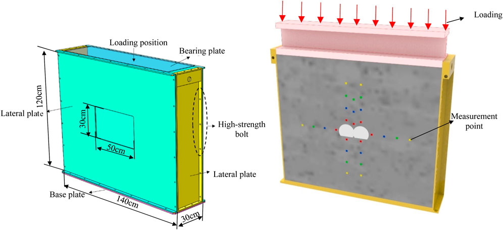
Figure 8. Model Test System, composed of channel steel, high-strength bolts, and acrylic plates.
The physical model was constructed by layered pouring. The main production steps are as follows: (1) Paste tin foil on the inside of the mold to make anti-friction paper, and mark the layer thickness of each layer of material, the buried point of strain brick and the position of supporting structure on one side of the anti-friction paper; (2) prepared the material referring to the Section 2.2.1, and stirred with a mixer for 15–20 min; (3) Layering and tamping the material from bottom to top, and then gouging to avoid obvious layering; (4) The measuring device and shotcrete anchor support model were buried at the marked points, and the location of the anchor rod needs to be compactor with a small rammer.
The model test adopts the test method of first loading and then excavation. First, the vertical stress is loaded step by step to 17.90 kPa, corresponding to an 8 kN force exerted by the jack, with each stage increment being 2 kN. Then the pressure is stabilized for about 2 h until the strain data is relatively stable. Subsequently, the left cavity was excavated sectional. The test excavation took 6 cm as a footage driving cycle until the tunnel was cut through. After each section of excavation, the pressure was maintained for about 30 min. After the completion of tunnel excavation, the pressure of the model was stabilized for 2 h, and then the overload test was carried out through the stress control mode. Each stage of load increments of 8 kN is loaded every 5 min until no further loading is possible or the tunnel collapses.
To facilitate the analysis and comparison of the cumulative quantity and dynamic quantity during stress adjustment, the stress release ratio (
where, σ0 and σ1 are the initial stress value and real-time stress value of the measuring point, respectively. n indicates the number of measurement points.
During tunnel excavation, the change of tangential stress reflects the internal adjustment of surrounding rock to resist the deformation caused by unloading (Nagessa et al., 2024). From Figure 9, tangential stress decreases overall, with different locations exhibiting varying magnitudes and rates of stress release throughout the excavation process. The stress release ratio of the left hole (about 68%) is higher than that of the right hole (about 46%), but the variation between the maximum and minimum stress release ratios is greater in the right hole. The reason for this phenomenon is that the advanced tunnel excavation can be regarded as a conventional single tunnel excavation, which disrupts the geo-stress balance of the top and bottom rock mass of the composite tunnel, causing the initial adjustment of stresses. Therefore, the secondary release of stresses caused by the subsequent tunnel excavation is lower than that of the advanced tunnel excavation. Moreover, due to the small spacing between the two tunnel sections, the stress environment and redistribution process in the subsequent tunnel are more complex, resulting in greater variability in stress attenuation across different locations within the tunnel. This ultimately leads to a relatively larger difference in the stress release ratio of the subsequent tunnel.
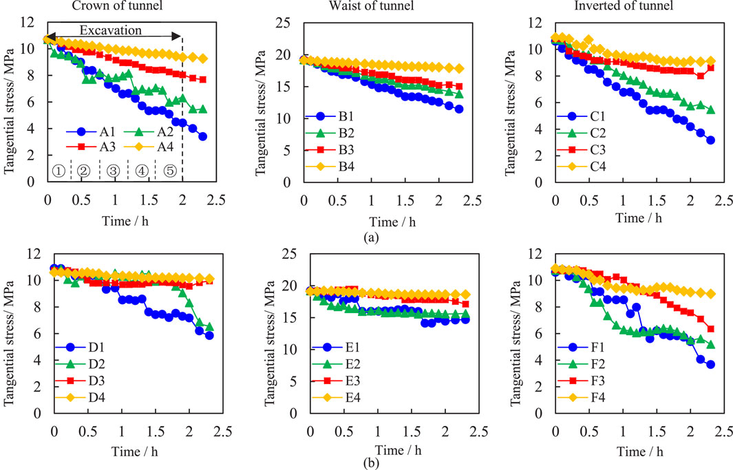
Figure 9. Tangential stress evolution of unsupported tunnel during the loading process. (a) Advance tunnel, (b) Subsequent tunnel.
It also can be seen that the stress attenuation of the 4 measuring points located at the invert of the two holes is obvious, and the measuring points of the surrounding rock are all in the plastic zone. Whereas, the tangential stress at the waist and crown of the two holes either remains undisturbed or exhibits minimal linear attenuation. This shows that the stability and self-adjustment ability of surrounding rock at invert are poor during tunnel excavation. In contrast, at the waist and crown, the surrounding rock is extruded with each other under the influence of excavation and unloading, which imparts a certain degree of self-stabilizing ability. However, due to the lack of external support, no stable and reliable pressure arch is formed, and the tangential stress of the surrounding rock is still released obviously near the inner wall of the tunnel.
Figure 10 shows the tangential stress evolution of supported tunnel, compared with Figure 9 it can be seen that the evolution of tangential stress is different on the unsupported and supported tunnel on the whole. The different evolutionary pattern arises from the pre-embedding of sprayed anchor support structures prior, with completion of the support structure following tunnel excavation. This approach effectively constrains rock mass deformation and mitigates excavation disturbance influence. Consequently, both left and right tunnels exhibit comparable stress evolution patterns. Additionally, due to the proximity of the tunnel-surrounding rock mass to the surface, despite limited support structure, it experiences swelling deformation. As a result, a stress attenuation zone of 9 cm in diameter near the tunnel wall while a stress concentration zone emerges at its farther end, creating a stable pressure arch bearing area.
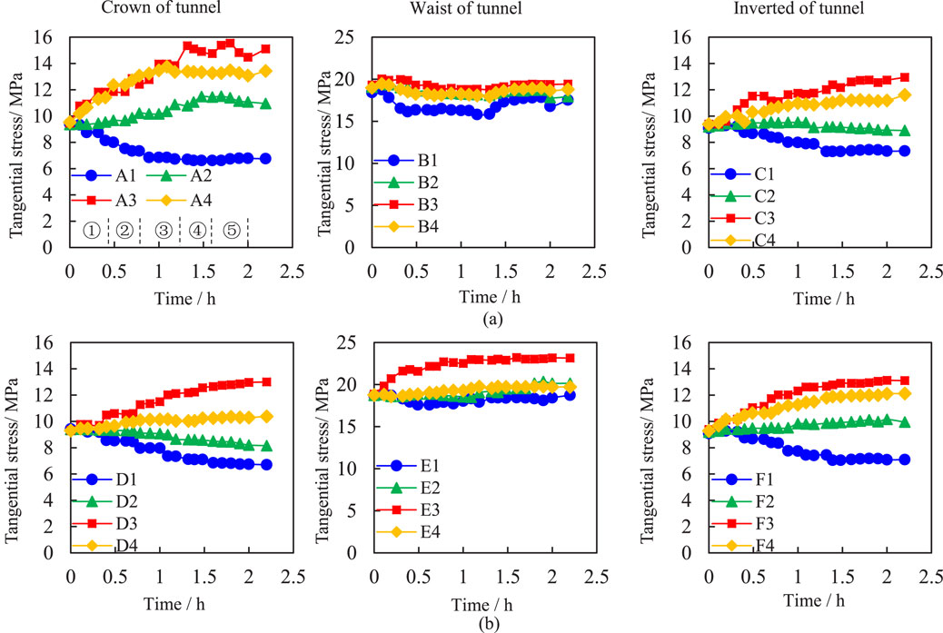
Figure 10. Tangential stress evolution of supported tunnel during the loading process. (a) Advanced tunnel, (b) Subsequent tunnel.
After the initial excavation, the tangential stress of A3 and A4 gradually increased to 11.8 kPa and 11.4 kPa, respectively, while the stress of other measuring points remained unchanged. After the second and third excavation, the tangential stress release ratio of measuring points A1 and D1 reaches 27.2% and 15.4%, respectively, resulting in obvious stepped attenuation. In the subsequent excavation stages, the tangential stress of measuring point No. 1 remained relatively stable. The stress evolution at measuring point No.2 of the two holes showed the greatest difference. The tangential stress at measuring point A2 increased to 10.2 kPa and the stress release ratio was −8.7%, while the tangential stress at measuring point D2 decreased to 9.1 kPa and the stress release ratio was 2.9%. This indicates that the surrounding rock at the advanced hole had formed a pressure arch and had the bearing capacity, but the surrounding rock at the subsequent hole was still in the plastic zone. The tangential stress at measuring points A3 and D3 continuously increased with excavation, reaching 13.8 kPa and 12.1 kPa, and the stress release ratios are −46.4% and −30%, respectively. Among the 4 measuring points, the tangential stress concentration phenomenon of surrounding rock is the most obvious, and the tangential stress release ratios at A4 and D4 measuring points are −40% and −7.8%, respectively. The tangential stress at these points was lower than that at No. 3 measuring point. It can be concluded that the surrounding rock of the measuring point A3 is in the core area of the elastic zone, the measuring point A4 is out of the core area of elastic zone, and the tangential stress of the measuring point D4 remained in the zone without significant fluctuation during the whole excavation process. After the fourth and fifth excavation, the tangential stress at measuring point A3 increased incrementally, while at measuring point D3, it increased linearly. The tangential stress of surrounding rock at other measuring points is relatively stable or changes slightly along the original trend, and the influence of excavation disturbance is not obvious.
The process of tangential stress redistribution of surrounding rock at the waist is relatively simple. The supporting structure significantly improves the stability of surrounding rock at the waist, with excavation disturbance having minimal impact on the tangential stress in this area. It can be seen that the tangential stress of the advanced hole presents a regular “step” increase with the step of excavation, while that of the subsequent hole is relatively insignificant. The three initial steps of excavation have a significant impact on the crown and waist of the tunnel. In the tangential stress concentration area, the stress release ratio changes greatly; in the tangential stress attenuation area, the supporting structure simultaneously reduces its decay ratio. The surrounding rock can fully realize its self-stability and load-bearing capacity in a long time.
As shown in Figure 11, the adoption of shotcrete anchor support resulted in a significant reduction in the average tangential stress release ratio of the rock mass. The tangential stress release ratios of the crown, waist, and invert of the left tunnel were −22.4%, 2.77%, and −9.92%, respectively, while those of the right tunnel were −2.28%, −8.9%, and −14.18%. Compared with the tangential stress release average ratio of the rock mass without support, the reduction in the same location of the two tunnel sections with support was similar. However, the average tangential stress release ratio in the left tunnel was lower when the two sections were compared with each other, indicating that the range of the rock mass pressure arch in the advanced tunnel was larger, and the self-stability and bearing capacity of the rock mass were stronger.
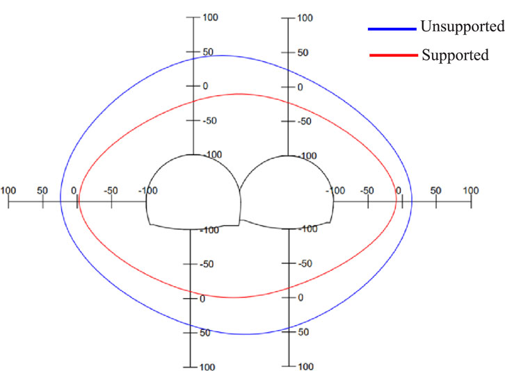
Figure 11. Comparison of stress release average ratio in surrounding rock before and after support.
Overall, the stress in the subsequent tunnel tends to decay, whereas the stress in the advanced tunnel tends to concentrate. This phenomenon can also be explained by the characteristics of this construction method. When the multi-arch tunnel is constructed without a central guide tunnel, it is excavated and formed in two stages, leading to a two-phase stress release in the surrounding rock due to the absence of additional supporting structures. In the process of excavation, the surrounding rock of the subsequent tunnel experiences continuous disturbance, so the overall stress release ratio of the advanced tunnel is usually higher than that of the subsequent tunnel. If the embedded support structure is used, stress redistribution will occur at the top and bottom of the surrounding rock of the subsequent tunnel during the excavation stage of the advanced tunnel, and the elastic zone will be formed in the surrounding rock within a certain range, resulting in the stress concentration in the first tunnel.
The multi-arch tunnel differs from the separate tunnel or the small clear distance tunnel in that it relies on the middle wall to bear most of the surrounding rock load. Therefore, the stability of the middle wall is very important to the overall stability of the tunnel structure. Figure 12a shows the stress evolution at the middle wall of tunnel without support, it can be seen that the horizontal stress of measuring points M1 and M2 decreases linearly, with the stress decay rate remaining nearly constant during excavation. Finally, the horizontal stress of the two measuring points decreases to 5.4 kPa and 6.9 kPa, and the stress decay ratios are 43.1% and 26.5%, respectively. Due to the distance from the middle partition wall, the horizontal stress of measuring point M3 remains consistent with the original rock stress. The corresponding vertical stress of surrounding rock showed a completely opposite variation. The vertical stress of surrounding rock at the top of the middle wall increased linearly and the stress release rate remained relatively constant. Additionally, the change amplitude of the vertical stress was also significantly greater than that of the horizontal stress. Finally, the vertical stress at the measuring point M1 and M2 increased to 34.2 kPa and 29.8 kPa respectively. The stress release ratios are −86.3% and −62.1%, representing the largest stress variations among all measuring points, which led to a pronounced stress concentration phenomenon. Meanwhile, the stress of measuring point M3 is also relatively stable. This phenomenon can be explained by the Figure 13, the double-arch tunnel can be regarded as a large single hole with a large single-hole collapse arch at the top. Individually, the double-arch tunnel can be regarded as two independent single holes with two independent pressure arches at the top, resulting in a crossed pressure arch is formed at the top of the middle wall. At the same time, due to the high stress release rate of the tunnel surrounding rock in the test without support, the vertical compression state of the surrounding rock is more obvious and the stress increases greatly.
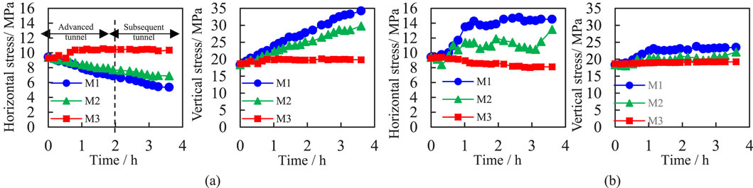
Figure 12. Stress evolution of surrounding rock at the top of the middle wall during the loading process. (a) Unsupported tunnel, (b) Supported tunnel.
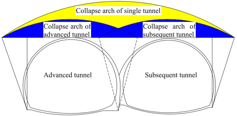
Figure 13. Schematic diagram of collapse arch for multi arch tunnel.
Figure 12b shows the stress evolution at the middle wall of tunnel with support, the shotcrete anchor support structure obviously changes the stress evolution at the top of the middle wall. The horizontal stress increases greatly during the whole excavation process of the two tunnel holes, and the stress release ratio is also difference obviously in each stage. The excavation disturbance of the left hole has a greater influence on the change of horizontal stress, while the horizontal stress of the right hole increases slightly during the excavation process. Finally, the stress at the measuring point M1 and M2 reach 14.5 kPa and 13.1 kPa, and the stress release ratios are −54.1% and −40.1%, respectively, while M3 measurement point is also still under the original rock stress due to the long distance. The variation trend of the vertical stress in the surrounding rock at the measuring point is the same as that in the test without support. The vertical stress at the measuring points M1 and M2 reach to 23.5 kPa and 22.1 kPa, and the stress release ratios are −28% and −20.4%, respectively. The original rock stress at the measuring point M3 is maintained, indicating that the variation of stress at the measuring point M1 and M2 is significantly reduced.
After the pressure was stabilized for 2 h after excavation, and 8 kN was pressed every 5 min according to the design scheme, continuing until the surrounding rock of the tunnel was completely compromised. In this process, the DIC measuring system was used to analyze the deformation and failure process of tunnel. As shown in Figure 14a, when the overload test is carried out in the unsupported tunnel, the upper surrounding rock of the back tunnel penetrates the advanced tunnel, and part of the surrounding rock of the middle wall has a counterclockwise rotational tendency in the plane, and the stable middle wall can transfer the displacement load to the bottom surrounding rock. At this stage, the left side of the surrounding rock of the middle wall is under compressive and the right side is under tensile, while the lower part is on the contrary. This leads to the tensile failure of the arch foot of the advanced tunnel and the vault of the subsequent tunnel in different programs. The failure develops rapidly at the initial stage of loading, but as the damage degree of the middle wall intensifies, the ability of transferring load is gradually lost, and the stress on the top of the two holes converges. Consequently, the crack propagation speed slows down, and the final failure mode can be seen in Figure 15a.
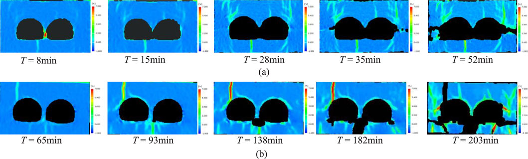
Figure 14. Strain field evolution in surrounding rock of tunnel. (a) unsupported tunnel, (b) supported tunnel.

Figure 15. Final failure of tunnel. (a) unsupported tunnel, (b) supported tunnel.
During the overload test of the support tunnel, as shown in Figure 14b, the damage degree of surrounding rock and support in the lower part of the tunnel is higher than that in the upper part of the tunnel. The deformation and failure of the tunnel are mainly due to that the surrounding rock at the bottom is subjected to tensile action, resulting in upward uplift deformation. The arch foot of the tunnel, located at the junction of the arch waist and invert, has low structural strength and exhibits significant stress concentration. When the compressive load of surrounding rock on the supporting structure exceeds its bearing capacity, the supporting structure will cause large deformation and even failure. The surrounding rock on both sides of the tunnel is squeezed into the bottom of the invert under the action of pressure, and shear failure occurs in the surrounding rock at the arch foot. This results in horizontal and vertical macroscopic cracks, and the final failure mode can be seen in Figure 15b.
To verify the validity of the model test, Figure 16 shows the comparison of the surrounding rock failure process of the unsupported tunnel model test and the numerical simulation results. It can be seen that as the vertical pressure at the top is applied, the failure process of the surrounding rock in the numerical simulation is similar to that of the model test, both showing severe damage in the middle wall area, with the surrounding rock first experiencing shear failure. As the pressure increases, the failure area expands from the free face at the arch waist to both sides. In the test, due to the lack of constraints on the observation surface, the surrounding rock surface begins to peel off. It can also be seen that the tunnel excavation face is significantly flattened, and the inverted arch is pressed to a horizontal position. With the further increase of the top pressure, the failure zone of the surrounding rock expands in the upper and lower directions outside the arch waist. It can also be seen from the test that a vertical through crack appears at the arch shoulder of the trailing tunnel, and with the loading, a large area of the surrounding rock eventually peels off at this location. In summary, the failure process of surrounding rock in the numerical simulation is in good agreement with the model test, which indicates the validity of the test.
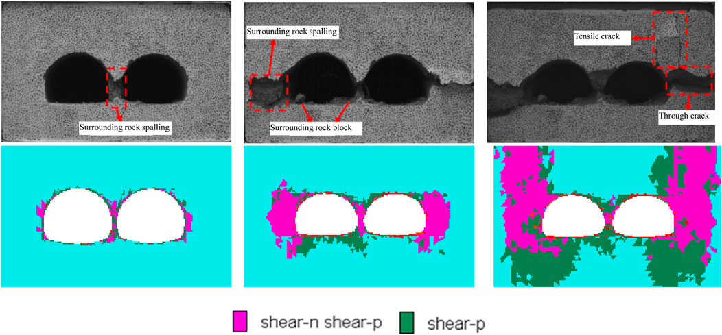
Figure 16. Comparison of model test and numerical simulation of surrounding rock damage process.
Scholars have conducted extensive experiments, theoretical analyses, and numerical simulations on the stability of surrounding rock in the double-arch tunnel without a middle pilot. Regarding non-symmetric double-arch tunnels, Min et al. (2020) explored the impact of voids behind the tunnel lining on the structural safety of the tunnel and investigated the real three-dimensional response of non-symmetric double-arch tunnels caused by voids. In terms of theoretical analysis, Sui et al. (2021) studied the continuous strain distribution of damaged linings in double-arch tunnels using distributed optical fiber sensing (DFOS) technology and analyzed their deformation patterns. Based on the fiber strain data, an inverse analysis method based on the curved beam theory to determine the deformation and stress state of the arch structure was proposed. In numerical research, Tang et al. (2022) verified the feasibility of the theoretical method through numerical analysis, studied the dynamic evolution and spatial distribution characteristics of surrounding rock pressure during tunnel excavation, and analyzed the influence of tunnel depth and surrounding rock properties on pressure distribution. However, the study on the fracture characteristics of surrounding rock and the influence of support on the excavation of the double-arch tunnel without a middle pilot is insufficient, so this work carried out the relevant research through the model test. The evolution process of radial stress and tangential stress of surrounding rock of tunnel during excavation was analyzed, and the influence of lining on the stability of surrounding rock during the construction of multi-arch tunnel without a middle pilot tunnel is revealed. And, the strain field of surrounding rock in physical model test was obtained by using XTDIC three-dimensional digital speckle full-field strain measurement and analysis system. Through the related research, the stress concentration location and corresponding fracture characteristics of the tunnel are determined, which can guide the design of support scheme.
In this paper, the model test of multi-arch tunnel without support and with shotcrete anchor support is designed to solve the engineering problem of multi-arch tunnel construction without a middle pilot tunnel under Class IV limestone stratum. Using the limestone similar materials and test equipment, the corresponding physical model tests were carried out, and the following conclusions are drawn:
(1) In the multi-step excavation of unsupported tunnel, the stress release ratio and damage degree in the advanced tunnel are higher. However, the stress redistribution process of the subsequent tunnel is more complex and more sensitive to the excavation response. The surrounding rock at the top of the middle wall shows the trend of linear decrease of horizontal stress and rapid linear increase of vertical stress, and the decay rate of both remains constant, reflecting the obvious anisotropic response characteristics.
(2) The supporting structure forms a stable pressure arch in the surrounding rock, extending the elastic zone both laterally and deeper into the tunnel. The variation of stress in the area of arch waist is relatively small. The stress at a distance of one tunnel diameter outside the tunnel wall decays rapidly, while a stress concentration area tends to form beyond this distance, where the stress release ratio is greater than in the stress decay area. The surrounding rock at the top of the middle wall remains relatively stable in the vertical direction, and presents obvious “bias effect” in the horizontal direction, and the stability of the surrounding rock of the middle wall is reduced by the excavation of the subsequent tunnel.
(3) When the overload test is carried out in the unsupported tunnel, the upper surrounding rock of the subsequent tunnel intrudes into the advanced tunnel, and some surrounding rock of the middle wall exhibits a counterclockwise rotational tendency in the plane. The damage degree of surrounding rock and support in the lower part of the tunnel is higher than that in the upper part of the tunnel with support.
However, the physical result is not verified by the field data and the numerical simulation result. Therefore, the numerical simulation should be done in future. And, the field data will be collected to verify the reasonability of the physical result.
The raw data supporting the conclusions of this article will be made available by the authors, without undue reservation.
JZ: Writing – original draft, Writing – review and editing, Investigation. W-LT: Writing – original draft, Writing – review and editing, Software. B-QZ: Writing – original draft, Investigation. S-QY: Writing – review and editing, Software.
The author(s) declare that no financial support was received for the research and/or publication of this article.
The authors declare that the research was conducted in the absence of any commercial or financial relationships that could be construed as a potential conflict of interest.
All claims expressed in this article are solely those of the authors and do not necessarily represent those of their affiliated organizations, or those of the publisher, the editors and the reviewers. Any product that may be evaluated in this article, or claim that may be made by its manufacturer, is not guaranteed or endorsed by the publisher.
Ambika, S., and Neelima, S. (2020). Understanding the impact of the arthquake on circular tunnels in different rock mass: a numerical approach. Innov. Infrastruct. So. 5 (8), 15–20.
Bi, T. J., Deng, Q., Tang, H., Jiang, C. Y., and Qin, Y. Q. (2024). Analytical solution of stress and displacement of double-arch tunnel without middle drift based on functions of complex variables. Rock Soil Mech. 45 (03), 777–787. doi:10.16285/j.rsm.2023.0380
Fumagalli, E. (1979). “Geomechanical models of dam foundation,” in Proceedings of the international colloquium on physical geomechanical models. Bergamo, Italy: ISRM.
Gu, J. C., Zheng, Q. P., Shen, J., and Ming, Z. Q. (1994). Model test study on the reinforcement effects of prestressed cable on homogenous rock mass. J. North China Inst. Water Conservancy Hydroelectr. Power 3, 69–76. doi:10.19760/j.ncwu.zk.1994.03.011
He, J., Zhang, C. P., Yang, G. B., and Wang, M. S. (2018). Experimental study on mechanical behavior of nonsymmetric multi-arch tunnel in sand-cobble ground. China Civ. Eng. J. 50 (4), 116–124. doi:10.15951/j.tmgcxb.2017.04.014
Heuer, R. E., and Hendron, A. J. (1971). “Geomechanical model study of the behavior of underground openings in rock subjected to static loads,” in Report 2. Tests on Unlined Openings in Intack Rock. ergebnisse der anatomie und entwicklungsgeschichte. doi:10.1063/1.468654
Jian, B. X., Tao, T. J., Song, S., Xie, C. J., Tian, X. C., Li, G. Q., et al. (2024). Damage and reliability analysis of double-arch tunnel without a middle pilot tunnel under blast load. Sci. Rep. 14, 9246. doi:10.1038/s41598-024-59681-5
Jiang, X., Liu, W., Yang, H., Shi, H. T., and Yu, L. (2021). Study on dynamic response characteristics of slope with double-arch tunnel under seismic action. Geotechnical Geol. Eng. 39 (8), 1349–1363. doi:10.1007/s10706-020-01562-5
Li, L. P., Shang, C. S., Chu, K. W., Zhou, Z. Q., Song, S. G., Liu, Z. H., et al. (2021). Large-scale geo-mechanical model tests for stability assessment of super-large cross-section tunnel. Tunn. Undergr. Sp. Tech. 109, 103756. doi:10.1016/j.tust.2020.103756
Li, S. C., Yuan, C., Feng, X. D., and Li, S. C. (2016). Mechanical behaviour of a large-span double-arch tunnel. Ksce J. Civ. Eng. 20 (7), 2737–2745. doi:10.1007/s12205-016-0456-y
Li, S. C., Yuan, C., Li, S. C., Feng, X. D., and Li, W. T. (2012). Model test study on mechanical behavior of extremely shallow double-arch tunnel during excavation. J. China Coal Soc. 37 (5), 713–718. doi:10.13225/j.cnki.jccs.2012.05.010
Lin, Q. B., Cao, P., Meng, J. J., Cao, R. H., and Zhao, Z. Y. (2020). Strength and failure characteristics of jointed rock mass with double circular holes under uniaxial compression: insights from discrete element method modelling. Theor. Appl. Fract. Mec. 109, 102692. doi:10.1016/j.tafmec.2020.102692
Lin, Q. B., Cao, P., Wen, G. P., Meng, J. J., Cao, R. H., and Zhao, Z. Y. (2021). Crack coalescence in rock-like specimens with two dissimilar layers and pre-existing double parallel joints under uniaxial compression. Int. J. Rock. Mech. Min. 139, 104621. doi:10.1016/j.ijrmms.2021.104621
Lin, Q. B., Zhang, S. C., Liu, H., and Shao, Z. L. (2024). Water saturation effects on the fracturing mechanism of sandstone excavating by TBM disc cutters. Arch. Civ. Mech. Eng. 24, 154. doi:10.1007/s43452-024-00964-z
Liu, B., Xu, F., Zhao, W. G., and Gao, Y. (2022). Review and prospect of model test system for tunnel engineering structure. Rock Soil Mech. 43 (S1), 452–468. doi:10.16285/j.rsm.2021.0737
Liu, T., Shen, M. R., Tao, L. B., He, Z. M., and Yuan, Y. (2006). Model test and 3D numerical simulation study on excavation of double-arch tunnel. Chin. J. Rock Mech. Eng. 25 (09), 1802–1808.
Meguid, M. A., Saada, O., Nunes, M. A., and Mattar, J. (2008). Physical modeling of tunnels in soft ground: a review. Tunn. Undergr. Sp. Tech. 23 (2), 185–198. doi:10.1016/j.tust.2007.02.003
Min, B., Zhang, C., Zhang, X., Wang, H. L., Li, P. F., and Zhang, D. L. (2020). Cracking performance of asymmetric double-arch tunnels due to the voids behind linings. Thin. Wall. Struc. 154, 106856. doi:10.1016/j.tws.2020.106856
Nagessa, Z. J., Siraj, M. A., and Eleyas, A. (2024). Numerical analysis of underground tunnel deformation: a case study of Midroc Lega-Dembi gold mine. Sci. Rep. 14, 7964. doi:10.1038/s41598-024-57621-x
Sterpi, D., and Cividini, A. (2004). A physical and numerical investigation on the stability of shallow tunnels in strain softening media. Rock Mech. Rock Eng. 37 (4), 277–298. doi:10.1007/s00603-003-0021-0
Sui, Y., Cheng, X. H., and Wei, J. X. (2021). Distributed fibre optic monitoring of damaged lining in double-arch tunnel and analysis of its deformation mode. Tunn. Undergr. Sp. Tech. 110, 103812. doi:10.1016/j.tust.2021.103812
Tang, H., Jiang, C. Y., Deng, Q., Bi, T. J., and Cha, Z. Y. (2022). Calculation of pressure on the shallow-buried double-arch tunnel without middle drift. Ksce J. Civ. Eng. 26 (11), 4805–4814. doi:10.1007/s12205-022-1958-4
Tian, L. G., Duan, Q. M., Xu, Q. W., and Cai, Y. C. (2013). Analysis and research on laboratory model test for twin-tunnel under unsymmetrical pressure. Chin. J. Undergr. Space Eng. 9 (1), 119–125.
Wang, C. S., Yong, R., Luo, Z. Y., Du, S. G., Karakus, M., and Huang, C. X. (2023). A novel method for determining the three-dimensional roughness of rock joints based on profile slices. Rock Mech. Rock Eng. 56, 4303–4327. doi:10.1007/s00603-023-03274-7
Wu, B., Lu, M., Huang, W., Lan, Y. B., Wu, Y. F., and Huang, Z. H. (2020). A case study on the construction optimization decision scheme of urban subway tunnel based on the TOPSIS method. Ksce J. Civ. Eng. 24 (11), 3488–3500. doi:10.1007/s12205-020-1290-9
Wu, B. T., Zhu, H. H., and Xu, Q. W. M. J. (2013). Experimental study of similar material for weak surrounding rock mass of class IV. Rock Soil Mech. 34 (S1), 109–116. doi:10.16285/j.rsm.2013.s1.044
Xiao, L. P., Zhao, Y. G., and Shen, Y. S. (2005). Model experimental study on style of structural internal force and stability of surrounding rock in double-arch tunnel. Chin. J. Rock Mech. Eng. 24 (23), 4346–4351.
Xie, G. J., Tao, T. J., and Rao, J. Y. (2022). Time-varying response analysis of surrounding rock construction mechanics of a double-arch tunnel without a middle pilot tunnel and suggestions for tunnel construction. Lithosphere 2022, 6306861. doi:10.2113/2022/6306861
Zeng, W. C., Zhou, Y. X., Zhai, J. L., and Xie, X. Y. (2019). Construction technology without middle drift and monitoring analysis of double-arch tunnel. Chin. J. Undergr. Space Eng. 15 (S1), 361–366.
Zhang, Q. Y., Li, S. C., Li, Y., and Wang, H. P. (2007). 3D geomechanical model test research on stability and supporting for surrounding rock mass of a large-scale diversion tunnel. Chin. J. Rock Mech. Eng. 26 (S2), 4051–4059.
Keywords: multi-arch tunnel, without a middle pilot tunnel, physical experiment, mechanical behavior, deformation and failure mechanism
Citation: Zhao J, Tian W-L, Zhang B-Q and Yang S-Q (2025) Experimental study on deformation and failure mechanism of the double-arch tunnel without a middle pilot. Front. Earth Sci. 13:1477727. doi: 10.3389/feart.2025.1477727
Received: 08 August 2024; Accepted: 03 April 2025;
Published: 16 April 2025.
Edited by:
Jeroen van Hunen, Durham University, United KingdomReviewed by:
Qibin Lin, University of South China, ChinaCopyright © 2025 Zhao, Tian, Zhang and Yang. This is an open-access article distributed under the terms of the Creative Commons Attribution License (CC BY). The use, distribution or reproduction in other forums is permitted, provided the original author(s) and the copyright owner(s) are credited and that the original publication in this journal is cited, in accordance with accepted academic practice. No use, distribution or reproduction is permitted which does not comply with these terms.
*Correspondence: Wen-Ling Tian, dGlhbndlbmxpbmczQDE2My5jb20=
Disclaimer: All claims expressed in this article are solely those of the authors and do not necessarily represent those of their affiliated organizations, or those of the publisher, the editors and the reviewers. Any product that may be evaluated in this article or claim that may be made by its manufacturer is not guaranteed or endorsed by the publisher.
Research integrity at Frontiers
Learn more about the work of our research integrity team to safeguard the quality of each article we publish.