- 1Disaster Reduction Center, China Institute of Water Resources and Hydropower Research, Beijing, China
- 2School of Computer and Information Engineering Tianjin Normal University, Tianjin, China
- 3State Key Laboratory of Simulation and Regulation of Water Cycle in River Basin, China Institute of Water Resources and Hydropower Research, Beijing, China
- 4Faculty of Geography, Tianjin Normal University, Tianjin, China
Introduction: This study investigates the backward erosion piping mechanism and its dependency on model size through both experiments and numerical simulations. The objective is to understand how different model dimensions affect the hydraulic gradients and piping behavior in dike systems.
Methods: Numerical simulations were performed using the finite element method (FEM), where the dike foundation was modeled in 3D and seepage flow was simulated under various hydraulic gradients. Physical experiments were also conducted using small-scale dike models to verify the numerical results and study the effects of model size.
Results and Discussion: The results show that in dikes without blanket layers, hydraulic gradients increase steadily as the piping channel develops, leading to upstream erosion and failure. In contrast, dikes with a blanket layer exhibit a stabilizing effect: the hydraulic gradient initially decreases before increasing, leading to a self-healing phenomenon that halts further channel progression. The study further reveals that the size effect—indicated by hydraulic gradients—diminishes with larger model dimensions and becomes negligible beyond a certain threshold. Additionally, the interaction between model width and depth significantly influences the progression of piping. These findings offer valuable insights for designing more resilient dike systems and improving flood protection strategies.
1 Introduction
Dike systems play a critical role in flood protection, yet they are persistently threatened by backward erosion piping—a process where seepage-induced soil particle removal leads to the formation and progression of subsurface channels. This phenomenon, if left unchecked, can cause catastrophic dike failures and widespread flooding, rising the water level, posing significant risks to communities and infrastructure (Qiu et al., 2024; Zhu et al., 2024). Previous studies, such as those by (Van Baars and Van Kempen, 2009), have emphasized the significant role of seepage and piping mechanisms in dike failures, highlighting that inadequate understanding of these processes can lead to catastrophic breaches. Their work underscores the critical need for effective mitigation strategies to address the challenges posed by backward erosion piping in flood protection systems. Similarly, Schmocker (2011) further contributes to this understanding by illustrating how dike material heterogeneity and foundation conditions are pivotal factors influencing the risk of erosion and failure. Additionally, The integration of geosynthetics into dike systems has been shown to significantly enhance resilience by controlling water-soil interactions, as highlighted by (Heibaum, 2014). Understanding these mechanisms is crucial for improving dike resilience and enhancing flood management strategies.
Furthermore, the structure of dike foundations plays a pivotal role in mitigating these risks. Dikes are typically built upon varying foundation types, which can influence the propagation of backward erosion piping. A key feature that significantly affects this process is the landside blanket layer—an impermeable or low-permeability layer that is placed between the dike core and the foundation. For dikes without this layer, once the piping channel begins, it tends to propagate unabated upstream, as there is no barrier to halt the erosion process. In contrast, the inclusion of a landside blanket layer provides a stabilizing effect. As shown by (Yao, 2014) and others, the presence of this layer initially reduces the hydraulic gradient at the piping tip, creating a self-stabilizing phenomenon that slows or even halts the channel’s progression temporarily. Over time, as the hydraulic gradient increases, the piping process resumes, but this phenomenon demonstrates a crucial difference in the erosion dynamics when compared to dikes without the blanket layer.
Numerous studies have investigated various aspects of backward erosion piping. For instance, Bersan et al. (2018) evaluate distributed temperature measurements for early detection of piping, linking hydraulic head variations to seepage-induced instability. On this basis, Akrami et al. (2021) provide insights into piping development in silty dike foundations, addressing mitigation through coarse sand barriers. Moreover, Bonelli (2013) analyze hydraulic head differentials as a trigger for backward erosion in dams and levees, offering a framework for geotechnical safety. Vandenboer et al. (2017) highlight the impact of leakage length on piping initiation and its implications for countermeasure effectiveness. Pol et al. (2019) analyze progression rates of backward erosion piping through laboratory experiments. Their study presents data from 45 controlled experiments and reliability analysis to refine models of erosion. Finally, Wewer et al. (2021) propose a transient backward erosion piping model using laminar flow transport equations. Gragnano et al. (2023) model innovative natural-based solutions for countering backward erosion piping, emphasizing sustainability. This study bridges experimental results and predictive modeling, enhancing understanding of piping initiation and development. These studies collectively enhance our understanding of the phenomenon, aiding in the development of more effective flood mitigation strategies.
However, there are few researches focusing on the size effect of the experiment models. A notable observation in backward erosion piping research is the profound impact of model size on the critical hydraulic head. Larger-scale models often exhibit lower critical heads, highlighting the scale dependency of piping phenomena. Further, the piping mechanism and the mode of channel propagation vary significantly across different foundation types, adding another layer of complexity to its study. For instance, Yao (2014) emphasized that the propagation patterns and critical conditions for piping differ in foundations with and without a landside impermeable blanket layer. In the absence of such a blanket layer, once a piping channel initiates, the erosion process continues relentlessly upstream without reaching equilibrium, ultimately leading to dike failure. This persistent propagation contrasts starkly with the equilibrium state often observed in experiments on foundations equipped with landside blanket layers, as reported by (Sellmeyer, 1988; Mao et al., 2004; Yao et al., 2007).
The three-dimensional finite element method (FEM) based on stable seepage theory provides new insights into the role of size-dependent mechanisms in the formation of piping, and elucidates the role of impermeable blanket layers in mitigating the backward erosion piping process. These simulations performed on homogeneous dike foundations both with and without landside impermeable blanket layers, have shed light on the size-dependent mechanisms driving piping. For example, Peng and Rice (2020) used FEM to analyze laboratory data, advancing our understanding of erosion mechanisms under controlled conditions. Similarly, Robbins et al. (2021) applied random FEM to model stochastic variations in piping progression, emphasizing the interplay between soil properties and hydraulic gradients. Wang et al. (2024) extended these approaches to temporal modeling, offering insights into the dynamic evolution of erosion pipes over time. The results underscore the interplay between dike geometry, seepage dynamics, and soil heterogeneity, which together govern the onset and progression of piping channels. These findings have significant implications for the design of resilient dike systems, especially in regions vulnerable to high seepage gradients.
While advancements in experimental and numerical methods have deepened our understanding of backward erosion piping, several questions remain unanswered. For example, what are the precise scaling laws governing the critical hydraulic head in large systems? How can foundational characteristics be optimized to resist persistent channel propagation in the absence of blanket layers? Addressing these questions is vital for developing effective countermeasures and predictive models for dike safety. The following sections delve into the experimental findings, computational analyses, and theoretical frameworks that collectively form the foundation of our current understanding of backward erosion piping.
2 Methods and implementation
2.1 Theoretical basis for numerical simulation of dike foundation piping
Understanding the theoretical framework underpinning numerical simulations is critical for accurately modeling backward erosion piping phenomena in dike foundations. Numerical simulations, particularly those employing the finite element method (FEM), offer a robust approach to analyze complex seepage and erosion interactions. These methods leverage governing equations of steady-state seepage and soil mechanics, incorporating factors such as anisotropic permeability and boundary conditions to replicate real-world conditions, the details are shown in the follows:
The continuous differential control equation of steady seepage in heterogeneous anisotropic porous media is:
The Factor
The boundary conditions for backward erosion piping in dike foundations consist of the water head and the flow boundary conditions. The water head boundary condition is as shown in Equation 2:
The flow boundary condition is:
The FEM Galerkin was used to discretize the governing Equation 1 and the equation can be derived as Equation 4:
where
The equivalent permeability
The factor λ is the friction factor of head loss of the piping channel,
2.2 Implementation of numerical simulation method for dike foundation piping
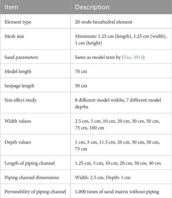
Firstly, the FEM is chosen for the numerical calculation based on the steady seepage theory, and the model is dispersed by 20-node hexahedral element, and appropriately increase the mesh around the pipe outlet and pipe channel to enhance the accuracy of the numerical simulation in regions where critical physical phenomena, such as erosion and seepage, are occurring. In this case, the pipe outlet and the developing piping channel are areas where high gradients in hydraulic head and rapid changes in flow can occur, making them more susceptible to errors when modeled with coarse meshes. The minimum mesh size is 1.25 cm in length, 1.25 cm in width, and 1 cm in height. Taking a model with a width and thickness of 50 cm as an example, based on the symmetry of the model, a model with half the width is taken for modeling calculation, that is, the model has a width of 25 cm and a depth of 50 cm, a total of 63,333 nodes, and 14,280 mesh cells are divided, as shown in Figure 1A.
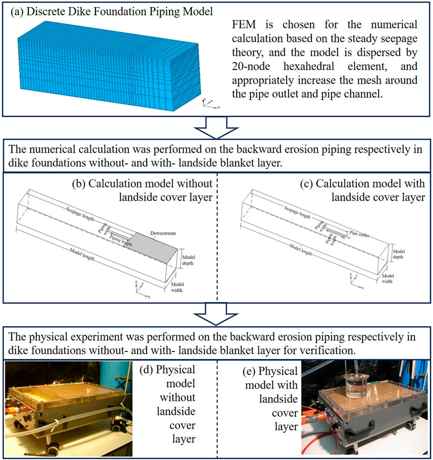
Figure 1. Research roadmap. (A) Discrete Dike Foundation Piping Model. (B) Calculation model without landside cover layer. (C) Calculation model with landside cover layer. (D) Physical model without landside cover layer. (E) Physical model with landside cover layer.
The numerical calculation was performed on the backward erosion piping respectively in dike foundations without- and with-landside blanket layer (Figures 1B, C). The parameters of sand are the same with the model tests by (Yao, 2014). 8 different model widths and 7 different model depths are set for the size effect study. The values of width are respectively 2.5 cm, 5 cm, 10 cm, 20 cm, 30 cm, 50 cm, 75 cm and 100 cm, and the values of depth are respectively 1 cm, 5 cm, 11.5 cm, 20 cm, 30 cm, 50 cm and 75 cm. The width and depth of piping channel are fixed 2.5 cm and 1 cm respectively. The seepage field of each size model with setting the length of piping channels as different present values under the fixed hydraulic head is analyzed. The permeability of the piping channel is simplified as 1,000 times of the sand matrix without piping (Liuqian et al., 2007). The numerical calculation model for dike foundation piping without- and with-landside cover (Figures 1B, C) have the same model length (70 cm), seepage length (50 cm) and the length of the piping channel taken as 1.25 cm, 5 cm, 10 cm, 20 cm, 30 cm and 40 cm. The summery of the model implementation is shown in Table 1.
The physical model is a closed box with dimensions of 0.5 m, 0.3 m, and 0.1 m in length, width, and height, respectively. The sample diameter length is controlled at 0.35 m. The body of the model slot is made of PVC board, and the top surface of the model slot is covered with organic glass board. The bottom of the organic glass board is coated with silicone gel (to increase the friction between the sand particles and the glass board, and to ensure close contact between the sand particles and the glass board with the elasticity of silicone gel). The glass board and the slot body are sealed with water stop strips and screws, as shown in Figure 1D.
The experimental model tank without landside cover layer has a closed top cover plate, which is blocked and fixed by upstream filter plates and downstream baffles. The upstream filter plate adopts a method of sandwiching geotextile between two layers of steel plates filled with small holes to ensure smooth water flow into the sand sample and prevent the sand sample from flowing into the upstream inlet part. The downstream baffle is slightly lower than the height of the sample to form a smaller slope on the downstream side of the sand sample, simulating the seepage outlet. The upstream inflow enters the sand sample through the opening on the right side of the model slot connected by a water pipe, passing through the upstream inflow part and the filter plate. The downstream outflow flows from the sloping seepage outlet to the downstream outflow part through the opening on the left side of the model box connected by a water pipe, as shown in Figures 1D,E.
The difference between the experimental model slot with landside cover layer and the model slot without landside cover layer lies in the design of the seepage outlet. For the model with a landside cover layer, a 6 mm diameter circular hole (Notice: the circular hole is an idealized representation, used for simplicity in the physical model. We have also emphasized the limitations of this approach and suggested that real-world leakage is more complex and irregular, influenced by factors such as soil heterogeneity, dike material defects, and variable hydraulic gradients) is pre-drilled in the centerline of the glass plate covering the top, 0.35 m from the upstream inlet, to simulate the outflow from a piping hole. The outflow of seepage water is designed to be retained by the upstream filter plate and the end of the model tank, with the tank being closed and the downstream side of the model tank sealed, allowing outflow only through the pre-drilled circular hole on the top. A transparent cylinder is installed above the hole, with a water pipe connected to the top of the cylinder, allowing seepage water to flow out through the hole, the cylinder, and the water pipe, as shown in Figure 1E.
Two piezometers are installed on the side of the model tank to reflect the variation process of the water head inside the embankment foundation and to verify any abnormalities in the water head during the experiment. A digital camera is fixed and suspended above the model tank, set to take timed automatic photos and store them on a server. The digital camera can capture the entire surface of the sand sample, allowing for continuous tracking of the development of piping channels on the sand surface. Additionally, another digital camera is available for capturing local piping phenomena at any time.
3 Result and discussion
For both homogeneous dike foundations with and without land cover layer, the distribution patterns of seepage fields under different model widths and thicknesses will be analyzed to reveal the variation in hydraulic gradient at the front end of the piping channel. This analysis aims to investigate the impact of model width and thickness on the embankment piping process and study the size effect of embankment piping models.
3.1 Backward erosion piping in dike foundations without landside blanket layer
In order to select reasonable boundary conditions, the influence of the upstream and downstream head difference on the hydraulic gradient of the pipe tip is analyzed. Select two models with different width and depth for analysis: (a) model with 30 cm width and 1 cm depth, (b) model with 50 cm width and 30 cm depth. Apply water head to the upstream and downstream of the models, gradually increasing the water head to simulate the development process of piping phenomenon. The water head gradually increases from 1 cm to 50 cm, with each increase being 1 cm. For the convenience of comparison, the hydraulic gradient of the pipe tip calculated at a water head of 1 cm is taken as the reference, and the ratio of the hydraulic gradient of the pipe tip calculated at different pipe channel lengths under each level of water head to the hydraulic gradient at 1 cm (hereinafter referred to as the relative hydraulic gradient of pipe tip) is compared with it.
Figure 2 shows the calculation results under different water head conditions. From the figure that under the same level of water head conditions, the relative hydraulic gradient of different lengths of pipe tip is the same, and this relative value increases linearly with the change of water head. Therefore, the distribution law of hydraulic gradient at the pipe tip under different head difference conditions is the same. Therefore, it is only necessary to study the distribution law of hydraulic gradient at the pipe tip under a certain head difference condition. This article takes the upstream and downstream head difference of 5 cm for calculation and analysis.
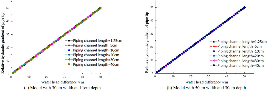
Figure 2. The relationship between hydraulic gradient and boundary conditions in the pipe tip. (A) Model with 30 cm width and 1 cm depth. (B) Model with 50 cm width and 30 cm depth.
The numerical calculations are performed on backward erosion piping in dike foundations without landside blanket layer with models of different widths and depths. The hydraulic gradients of the tip of the piping channel are acquired and their variation trends with the piping channel length increase are shown with different model widths and depths (Figure 3).
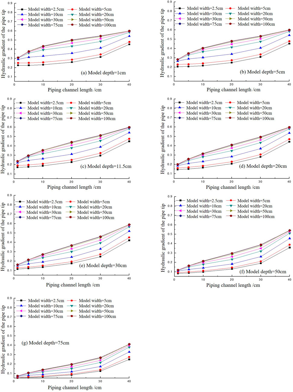
Figure 3. The variation of the hydraulic gradient with the pipe length increasing in different model widths and depths in dike foundations without landside blanket layer. (A) Model depth-1 cm. (B) Model depth-5 cm. (C) Model depth-11.5 cm. (D) Model depth 20 cm. (E) Model depth-30 cm. (F) Model depth-50 cm. (G) Model depth-75 cm.
Figure 3 shows the variation of the hydraulic gradient of the pipe tip with the length of the piping channel. As shown in Figure 3 that when the piping channel is relatively short, i.e., when the piping channel begins to form, the smaller the model width, the smaller the hydraulic gradient at the front of the piping channel. Therefore, under the same critical condition for the initial formation of the piping channel at the dike foundation, a model with a smaller width requires a higher head to reach the initial conditions for piping compared to a model with a larger width. It can also be seen that as the piping channel develops upstream and the length of the piping channel increases, the hydraulic gradient at the front of the piping channel increases under all width and depths conditions, showing a monotonous upward trend. Therefore, once the piping channel begins to form, the hydraulic gradient at the pip tip will continue to increase, indicating that once the piping channel forms, it cannot be stopped and will continue to develop upstream until scour damage occurs when it connects with the upstream. This also implies that under the model conditions, the initial gradient at the formation of the piping channel at the dike foundation represents the critical gradient for piping failure.
Additionally, in Figure 3, subfigures (a) to (g) illustrate an increase in model depth from 1 cm to 75 cm. Despite this variation, the patterns observed in each subfigure remain similar. This similarity suggests that, when the model width is kept constant, the gradient of the pipe tip also increases with the length of the piping channel. Consequently, both model width and model depth appear to have minimal impact on the observed phenomenon: once the pipe initiation occurs, it continues unabated until it reaches the upstream, as previously reported in model tests (Yao, 2014; Yao et al., 2013).
The observations from Figure 3 regarding the influence of model depth on the hydraulic gradient are further supported by the data presented in Figure 4, which examines the variation of the hydraulic gradient with model width and depth. In both cases, it is evident that the dimensions of the model, whether depth or width, play a similar role in determining the hydraulic gradient at the pipe tip.
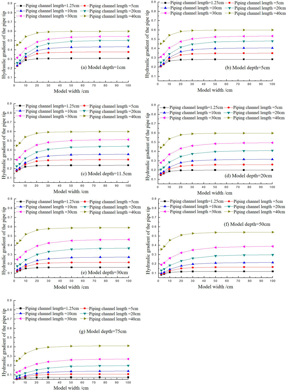
Figure 4. The variation of the hydraulic gradient of the pipe tip with the increase of model width and depth with different piping channel lengths. (A) Model depth=1 cm. (B) Model depth-5 cm. (C) Model depth-11.5 cm. (D) Model depth-20 cm. (E) Model depth-30 cm. (F) Model depth 50 cm. (G) Model depth-75 cm.
As shown in Figure 4, the variation trend of the hydraulic gradient of the piping face with model width under different piping channel lengths. From the graph, it can be observed that under the same piping channel length, when the model width is small, the hydraulic gradient on the pipe tip differs significantly for different model widths. As the model width increases, the difference gradually becomes smaller, and once the model width reaches a certain size, the hydraulic gradient on the piping face becomes nearly identical, approaching a constant value. This indicates that when the model width is small, the hydraulic gradient at the pipe tip has a significant impact, thus affecting the critical gradient for piping failure. Once the model width reaches a certain size, the difference diminishes as the model width increases, and the influence of model width on the piping development process can be considered negligible. The similar situation can be observed in all model depths in Figures 4A–G, indicating that the effect of model depths has the same pattern with model widths.
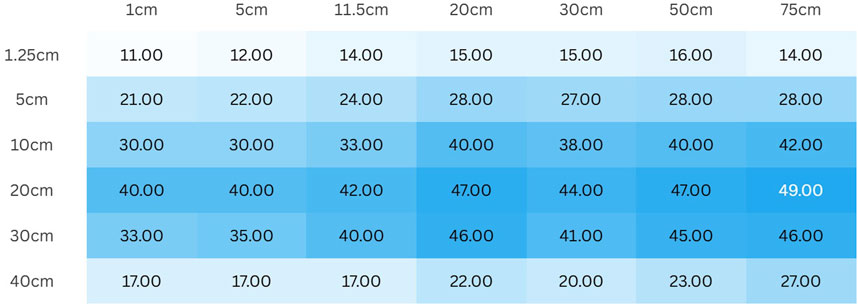
Based on the benchmark of calculating the hydraulic gradient at the pipe tip when the maximum model width is 100 cm, analyze the relative value of the hydraulic gradient
From Figure 5, it can be observed that the model width required to achieve the tolerance error is not a single value but is related to the model depths. The smaller the model depth, the smaller the model width required to achieve the tolerance error; conversely, the larger the model thickness, the larger the model width required to achieve the tolerance error.
Based on the benchmark of calculating the hydraulic gradient at the pipe tip when the maximum model depth is 75 cm, analyze the relative value of the hydraulic gradient
From Figure 6 reflects the depth of the model required to tolerate errors is not significantly related to the width of the model. The required model depth decreases with increasing pipeline channel length.
3.2 Backward erosion piping in dike foundations with landside blanket layer
In order to select reasonable boundary conditions, the influence of the upstream and downstream head difference on the hydraulic gradient of the pipe tip is analyzed. Select two models with different width and depth for analysis: (a) model with 100 cm width and 75 cm depth, (b) model with 100 cm width and 1 cm depth, (c) model with 2.5 cm width and 75 cm depth. Apply water head to the upstream and downstream of the models, gradually increasing the water head to simulate the development process of piping phenomenon. The water head gradually increases from 1 cm to 50 cm, with each increase being 1 cm. For the convenience of comparison, the hydraulic gradient of the pipe tip calculated at a water head of 1 cm is taken as the reference, and the ratio of the hydraulic gradient of the pipe tip calculated at different pipe channel lengths under each level of water head to the hydraulic gradient at 1 cm (hereinafter referred to as the relative hydraulic gradient of pipe tip) is compared with it.
Figure 7 shows the calculation results under different water head conditions. The figure shows that under the same level of water head conditions, the relative hydraulic gradient of different lengths of pipe tip is the same, and this relative value increases linearly with the change of water head. Therefore, the distribution law of hydraulic gradient at the pipe tip under different head difference conditions is the same. Therefore, it is only necessary to study the distribution law of hydraulic gradient at the pipe tip under a certain head difference condition. This article takes the upstream and downstream head difference of 5 cm for calculation and analysis.
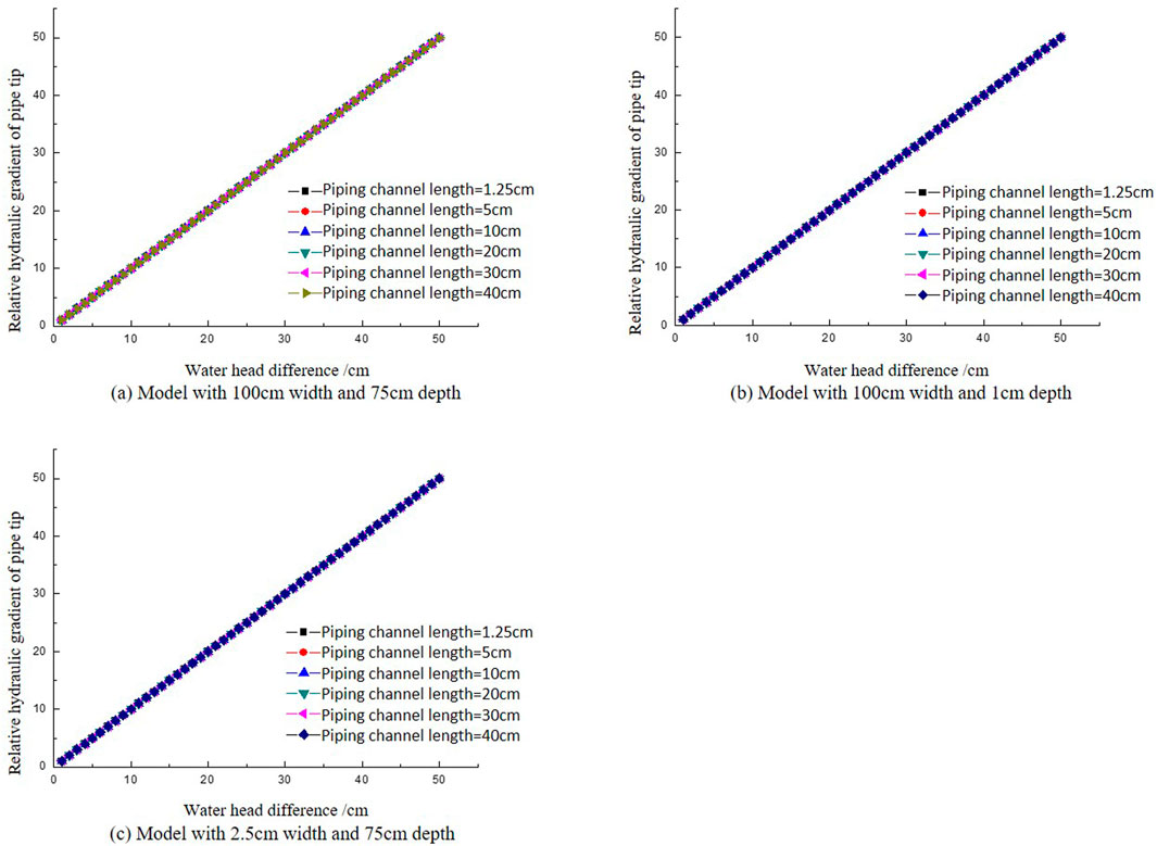
Figure 7. The relationship between hydraulic gradient and boundary conditions in the pipe tip. (A) Model with 100 cm width and 75 cm depth. (B) Model with 100 cm width and 1 cm depth. (C) Model with 2.5 cm width and 75 cm depth.
It is different with the calculation results of backward erosion piping in dike foundations without landside blanket layer, the values of hydraulic gradient of the pipe tip do not increases monotonically but decrease firstly and then increase with the pipe length increasing in dike foundations with landside blanket layer (Figure 8). As shown in Figure 8, the variation of the hydraulic gradient on the pipe tip with changes in the piping channel length, it can be observed that under the condition of equal upstream and downstream head differences, when the piping channel length is relatively short, the smaller the model width, the smaller the corresponding hydraulic gradient on the pipe tip. As a result, models with smaller widths require a higher head difference to reach the same initial conditions for piping formation compared to models with larger widths. In other words, models with larger widths require a lower head difference to form a piping channel. And that is the same as the dike foundations without landside blanket layer.
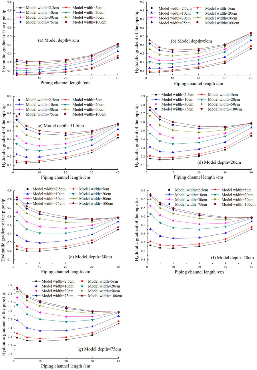
Figure 8. The variation of the hydraulic gradient with the pipe length increasing in different model widths in dike foundations with landside blanket layer. (A) Model depth-1cm. (B) Model depth-5 cm. (C) Model depth-11.5 cm. (D) Model depth = 20 cm. (E) Model depth = 30 cm. (F) Model depth 50 cm. (G) Model depth = 75 cm.
When the model width is small and the model depth is also small (as shown in Figure 8A with a model depth of 1 cm, and widths of 2.5 cm, 5 cm, 10 cm, 20 cm, and in Figure 8B with a model depth of 5 cm, and widths of 2.5 cm, 5 cm), as the piping channel length increases, the hydraulic gradient on the pipe tip gradually increases, showing a monotonically rising trend. Moreover, the rate of increase becomes more significant, indicating that during the upstream development of the piping, it follows an unstoppable trend. Once the piping channel forms, it quickly connects the upstream and downstream. This condition is only used for comparison between different sizes and simulates an extreme situation.
When the model width is small but the model depth is sufficiently large (as shown in Figures 8C–G), the hydraulic gradient on the pipe tip, as the piping channel length increases, no longer follows a monotonically increasing trend. Instead, it initially decreases before increasing, creating a concave-up curve. This trend suggests that during the early stage of piping channel formation, the hydraulic gradient on the pipe tip decreases, potentially dropping below the critical gradient. As a result, the piping channel halts its development and reaches a stable equilibrium. As the head increases, the piping channel extends upstream to a certain length, and the hydraulic gradient increases, surpassing the critical value, breaking the equilibrium and causing the piping to continue its development. The calculation results show that, under conditions with a landside blanket layer, there is a self-healing phenomenon during the development of the channel. This is consistent with the phenomenon observed in (Guo et al., 2024).
As shown in Figure 9, the variation trend of hydraulic gradient on the pipe tip with the model width under different piping channel lengths. Figure 9 shows that under the same piping channel length conditions, when the model width is relatively small, the hydraulic gradient on the pipe tip with different model widths varies greatly. As the model width gradually increases, the difference tends to flatten. When the model width reaches a certain size, the hydraulic gradient on the pipe tip almost does not differ much and tends to a constant value. This indicates that when the model width is small, it has a greater impact on the hydraulic gradient of the front end of the piping channel, and therefore has a greater impact on the critical gradient of piping failure. After the model reaches a certain width, as the model width increases, this difference gradually approaches zero, and the influence of model width on the development process of piping can be basically ignored. This trend can be observed in all sub-figures (a-g) in Figure 9, indicating that the effect of model depth has the same pattern with model width. So, in dike foundations with landside blanket layer, it is consistent with calculation analysis of the size effect on backward erosion piping in dike foundations without landside blanket layer that the model influence is decreasing and going to be zero when the model size reaches to large enough (Figure 4).
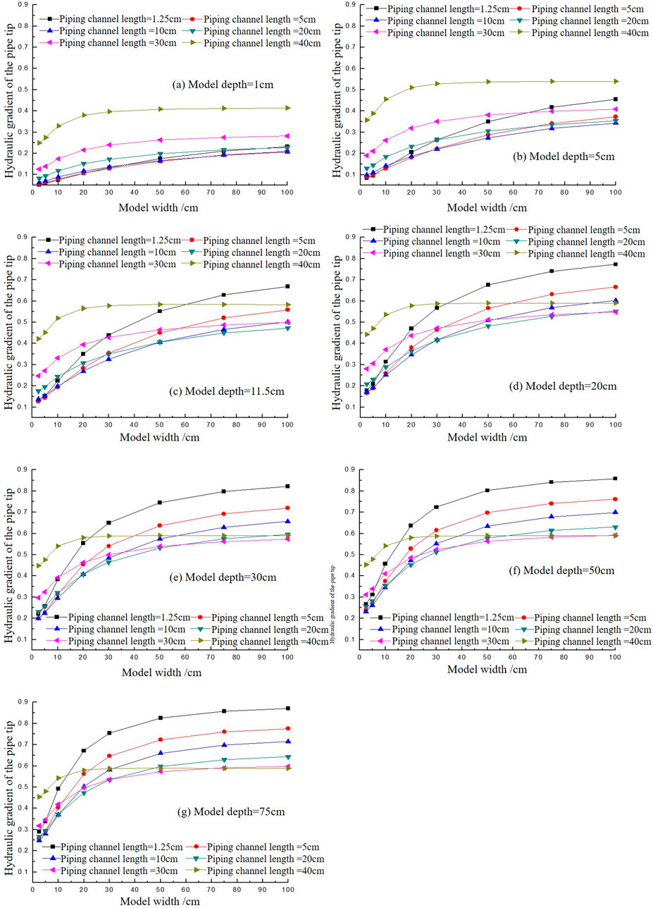
Figure 9. The variation of the hydraulic gradient of the pipe tip with the increase of model width with different piping channel lengths. (A) Model depth = 1 cm. (B) Model depth = 5 cm. (C) Model depth = 11.5 cm. (D) Model depth 20 cm. (E) Model depth-30 cm. (F) Model depth-50 cm. (G) Model depth-75 cm.
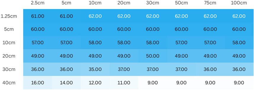
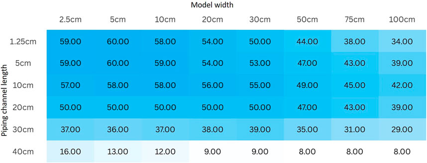
Based on the benchmark of calculating the hydraulic gradient at the pipe tip when the maximum model width is 100 cm, analyze the relative value of the hydraulic gradient
As shown in Figure 10, the model width required to achieve the tolerable error generally falls between 70 cm and 90 cm. Therefore, when the model width is set at 1.8 times the seepage path, its impact can be largely ignored.
Based on the benchmark of calculating the hydraulic gradient at the pipe tip when the maximum model depth is 75 cm, analyze the relative value of the hydraulic gradient
As shown in Figure 11, the depth of the model with landside blanket layer required to tolerate errors is not significantly related to the width of the model. The required model depth decreases with increasing pipeline channel length. This is consistent with the model without landside blanket layer.
3.3 Physical experiment for verification
A small-scale physical model is used to conduct experimental verification on the piping of dike foundations with homogeneous permeable layers under the conditions of no landside cover layer and with landside cover layer. The physical properties of sand samples are listed in Table 2.
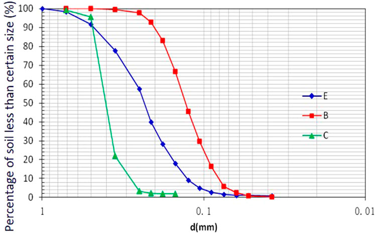
The particle size distribution curve of the experimental sand sample is shown in Figure 12:
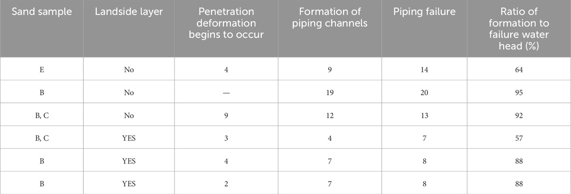
The sand samples of dike foundation piping are globally photographed and tracked, and the required water head for each typical stage are shown in Table 3.
According to Table 3, for the dike foundation without landside cover, the ratio of ratio of formation to failure water head is the highest at 95% and for the dike foundation with landside cover, the ratio of ratio of formation to failure water head is the lowest at 57%. The experimental results show that the dike foundation without landside cover will not form obvious piping channels before reaching the critical water head. Even if piping channels are formed, their scale is very small and cannot be strictly called piping channels. At the critical head, there will only be a significant upward development of the piping channel. Once it appears, it will not stop until it is connected to the upstream and experiences erosion damage. As observed in earlier experiments (Yao, 2014), these channels continued to propagate upstream without any self-regulation, leading to eventual failure of the dike foundation. And this is consistent with the numerical simulation results showed in Figure 3 that as the piping channel develops upstream and the length of the piping channel increases, the hydraulic gradient at the front of the piping channel increases under all width and depths conditions, showing a monotonous upward trend.
Compared to the situation without landside blanket layer, under the test conditions with landside blanket layer, the ratio of the water head formed by the piping channel to the critical water head for piping failure is slightly lower, with the highest ratio being 88% and the lowest being 57%, as shown in Table 3. In the initial stage of destruction, after the formation of the piping channel, there is a “self-healing” phenomenon of stop and go before falling below the critical water head, but the length of the channel is still limited, only a few centimeters. This pattern is consistent with the self-stabilizing effect of impermeable layers observed in the numerical model results showed in Figure 8 that during the early stage of piping channel formation, the hydraulic gradient on the pipe tip decreases, potentially dropping below the critical gradient, as a result, the piping channel halts its development and reaches a stable equilibrium.
While the general trends aligned well, there were some differences between the numerical and physical results, such as the sand sample E without landside blanket layer, the physical experiment result in Table 3 which should be similar to the sand sample B without landside blanket layer according to the numerical model. This can be attributed to several factors: Firstly, the numerical model made certain simplifications to reduce computational complexity. For instance, assumptions such as isotropic soil permeability or simplified boundary conditions (e.g., neglecting transient effects or small-scale heterogeneities) may not fully represent the real-world behavior observed in the physical experiments. Secondly, in the physical experiments, inflow and outflow conditions were controlled more directly, but minor variations in the experimental setup (such as slight differences in soil compaction or water head application) could introduce deviations. In contrast, the numerical model simulated a more uniform flow distribution based on idealized boundary conditions, which may not always match the complex flow dynamics seen in the physical setup.
4 Conclusion
This research provides a comprehensive analysis of the backward erosion piping mechanism and its size effects in dike foundations, incorporating numerical simulations, experimental validations, and theoretical interpretations. It reveals several critical conclusions.
1. The study demonstrates that the dimensions of experimental models significantly influence the critical hydraulic gradients and the progression of piping channels. Smaller widths and depths necessitate higher hydraulic heads to initiate piping, while larger dimensions mitigate these effects, with the influence diminishing when the model reaches a sufficiently large size.
2. The physical experimental results show that dike foundations without a landside cover form piping channels only after reaching the critical water head, with the channels propagating upstream without self-regulation, leading to eventual failure, consistent with the numerical simulations showing an increasing hydraulic gradient as the piping channel develops. For dikes with a landside blanket layer, the formation of piping channels occurs at a lower water head, with a “self-healing” phenomenon observed in the early stages, where the hydraulic gradient decreases, halting channel development temporarily, which is consistent with the numerical model results that during the early stage of piping channel formation, the hydraulic gradient on the pipe tip decreases, potentially dropping below the critical gradient.
3. The findings underscore the need to consider size effects in laboratory tests and the design of mitigation strategies for backward erosion piping. Recommendations include scaling experimental models appropriately and incorporating landside blanket layers to enhance dike stability.
Although the research offers significant insights into the backward erosion piping mechanism and its size effects in dike foundations, it acknowledges certain limitations. Despite the meticulous design of the experimental setup to emulate real-world conditions, achieving perfect replication of natural environments remained challenging. Minor inconsistencies in outcomes were observed, attributed to uncontrollable variations in water head application and soil compaction. To build upon these findings, future studies could enhance the Finite Element Method (FEM) approach by integrating transient seepage dynamics and accounting for soil heterogeneity and multi-phase flow. This would involve considering both water and air phases within piping channels, providing a more realistic portrayal of time-dependent processes. Additionally, incorporating nonlinear permeability models machine learning methods (Wei et al., 2024) and random field methods to simulate variable soil properties would further bolster the FEM model’s robustness and applicability to real-world dike foundations, where dynamic flow conditions and soil variability are prevalent.
Data availability statement
The raw data supporting the conclusions of this article will be made available by the authors, without undue reservation.
Author contributions
QY: Conceptualization, Data curation, Formal Analysis, Investigation, Methodology, Project administration, Resources, Software, Supervision, Validation, Visualization, Writing–original draft, Writing–review and editing. XY: Data curation, Formal Analysis, Investigation, Methodology, Software, Supervision, Validation, Visualization, Writing–review and editing. ZW: Formal Analysis, Investigation, Methodology, Software, Supervision, Validation, Visualization, Writing–review and editing. HH: Formal Analysis, Investigation, Methodology, Software, Supervision, Validation, Writing–review and editing. MM: Data curation, Formal Analysis, Funding acquisition, Investigation, Methodology, Project administration, Resources, Software, Supervision, Validation, Writing–original draft.
Funding
The author(s) declare that financial support was received for the research, authorship, and/or publication of this article. This research was supported by the OpenExtreme21GFund of the China institute of Water Resources and Hydropower Research (IWHR-SKL-KF202310), “Five talents” Plan of the China Institute of Water Resource and Hydropower Research (WH0145B062022), and National Natural Science Foundation of China (42101086,42371086).
Conflict of interest
The authors declare that the research was conducted in the absence of any commercial or financial relationships that could be construed as a potential conflict of interest.
Generative AI statement
The authors declare that no Generative AI was used in the creation of this manuscript.
Publisher’s note
All claims expressed in this article are solely those of the authors and do not necessarily represent those of their affiliated organizations, or those of the publisher, the editors and the reviewers. Any product that may be evaluated in this article, or claim that may be made by its manufacturer, is not guaranteed or endorsed by the publisher.
References
Akrami, S., Bezuijen, A., van Beek, V., Rosenbrand, E., Terwindt, J., and Förster, U. (2021). Analysis of development and depth of backward erosion pipes in the presence of a coarse sand barrier. Acta Geotech. 16 (2), 381–397. doi:10.1007/s11440-020-01053-0
Bersan, S., Koelewijn, A. R., and Simonini, P. (2018). Effectiveness of distributed temperature measurements for early detection of piping in river embankments. Hydrology Earth Syst. Sci. 22 (2), 1491–1508. doi:10.5194/hess-22-1491-2018
Gragnano, C. G., Camiletti, F., Forbicini, F., Gottardi, G., Marchi, M., and Tonni, L. (2023). “Physical modelling of backward erosion piping for the development of natural-based mitigation strategies,” in Paper presented at national conference of the researchers of geotechnical engineering (Springer).
Guo, H., Ren, J., Zhang, L., Kang, J., Nan, S., Chen, K., et al. (2024). Experimental study on backward erosion piping of a double-layer dike foundation under variable exit geometries. Transp. Geotech. 48, 101353. doi:10.1016/j.trgeo.2024.101353
Heibaum, M. (2014). Geosynthetics for waterways and flood protection structures–Controlling the interaction of water and soil. Geotext. Geomembranes 42 (4), 374–393. doi:10.1016/j.geotexmem.2014.06.003
Liuqian, D., Mengxi, W., and Changjun, L. (2007). Numerical simulation of dynamic development of piping in two-stratum dike foundations. Water Resour. Hydropower Eng. 38 (2), 36–39.
Mao, C., Duan, X., Cai, J., and Ru, J. (2004). Experimental study on harmless seepage piping in levee foundation. J. Hydraul. Eng. 35 (11), 46–53.
Peng, S., and Rice, J. D. (2020). Inverse analysis of laboratory data and observations for evaluation of backward erosion piping process. J. Rock Mech. Geotechnical Eng. 12 (5), 1080–1092. doi:10.1016/j.jrmge.2020.05.007
Pol, J., Van Beek, V., Kanning, W., and Jonkman, S. N. (2019). “Progression rate of backward erosion piping in laboratory experiments and reliability analysis,” in Paper presented at 7th international symposium on geotechnical safety and risk (ISGSR) (Tapei: Research Publishing).
Qiu, H., Su, L., Tang, B., Yang, D., Ullah, M., Zhu, Y., et al. (2024). The effect of location and geometric properties of landslides caused by rainstorms and earthquakes. Earth Surf. Process. Landforms 49 (7), 2067–2079. doi:10.1002/esp.5816
Robbins, B., Griffiths, D., and Fenton, G. A. (2021). Random finite element analysis of backward erosion piping. Comput. Geotechnics 138, 104322. doi:10.1016/j.compgeo.2021.104322
Sellmeyer, J. B. (1988). On the mechanism of piping under impervious structures. Delft, The Netherlands: Technische Universiteit Delft.
Van Baars, S., and Van Kempen, I. (2009). The causes and mechanisms of historical dike failures in The Netherlands. Hennef, Germany: E-Water Official Publication of the European Water Association, 1–14.
Vandenboer, K., van Beek, V. M., and Bezuijen, A. (2017). “Pipe depth measurement in small-scale backward erosion piping experiments,” in Paper presented at 25th meeting European working group on internal erosion in embankment dams and their foundations.
Wang, Z., Oskay, C., and Fascetti, A. (2024). Three-dimensional numerical modeling of the temporal evolution of backward erosion piping. Comput. Geotechnics 171, 106381. doi:10.1016/j.compgeo.2024.106381
Wei, Y., Qiu, H., Liu, Z., Huangfu, W., Zhu, Y., Liu, Y., et al. (2024). Refined and dynamic susceptibility assessment of landslides using InSAR and machine learning models. Geosci. Front. 15 (6), 101890. doi:10.1016/j.gsf.2024.101890
Wewer, M., Aguilar-López, J. P., Kok, M., and Bogaard, T. (2021). A transient backward erosion piping model based on laminar flow transport equations. Comput. Geotechnics 132, 103992. doi:10.1016/j.compgeo.2020.103992
Yao, Q. (2014). “Multi-size experiments and numerical simulation for backward erosion piping in dike foundations,” in Ph. D. Thesis, dept. Of geotechnical engineering, China institute of water.
Yao, Q., Ding, L., Sun, D., Liu, C., and Zhang, Q. (2007). Experimental studies on piping in single-and two-stratum dike foundations. Water Resour. Hydropower Eng. 38 (2), 13–18.
Yao, Q., Van Beek, V., Van, M., and Ding, L. (2013). “Backward piping in multi-layer dike foundations: experiments and model validation,” in Paper presented at 2013. Chengdu, China: (IAHR World Congress).
Keywords: backward erosion piping, size effect, mechanism, development mode, dike foundations
Citation: Yao Q, Yan X, Wu Z, Hao H and Ma M (2025) Backward erosion piping mechanism in dike foundations with and without landside blanket layers: numerical simulation of size effects. Front. Earth Sci. 12:1537390. doi: 10.3389/feart.2024.1537390
Received: 30 November 2024; Accepted: 17 December 2024;
Published: 08 January 2025.
Edited by:
Haijun Qiu, Northwest University, ChinaReviewed by:
Chaojie Wang, Zhengzhou University, ChinaWang Xiangpeng, Chengdu University of Technology, China
Copyright © 2025 Yao, Yan, Wu, Hao and Ma. This is an open-access article distributed under the terms of the Creative Commons Attribution License (CC BY). The use, distribution or reproduction in other forums is permitted, provided the original author(s) and the copyright owner(s) are credited and that the original publication in this journal is cited, in accordance with accepted academic practice. No use, distribution or reproduction is permitted which does not comply with these terms.
*Correspondence: Meihong Ma, TW1oa2wyMDA3QDE2My5jb20=
†Present address: Xiping Yan, Tianjin Key Laboratory of Water Resources and Environment, Tianjin Normal University, Tianjin, China
‡These authors share first authorship
 Qiuling Yao1‡
 Xiping Yan
 Meihong Ma