 Wei Wang1,2,3
 Jingzhong Zhu
- 1CCTEG Xi’an Research Institute (Group) Co., Ltd., Xi’an, China
- 2State Key Laboratory of Coal Mine Disaster Prevention and Control, Xi’an, China
- 3Shaanxi Key Laboratory of Prevention and Control Technique for Coal Mine Water Hazard, Xi’an, China
- 4School of Resources and Geosciences, China University of Mining and Technology, Xuzhou, China
With the high-intensity mining activities and the selection of interval mining methods, a large amount of high-rank coal resources are left in the underground space (isolated islands). However, due to the complicated mining geological conditions, the coal resources in the isolated islands have not been fully extracted. In this paper, the mechanism of water inrush from limestone aquifers under isolated island panels is discussed from theoretical mechanics analysis, numerical simulation, discriminant criterion, the variation law of surrounding rock stress and water pressure, and floor failure depth. Meanwhile, we take the coal mining of the isolated island shaft in the Zhuzhuang colliery, Huaibei mining area, as an application case and propose the key technique of limestone water disaster prevention and control. Eventually, the treatment effect is validated by the practical work. The study results indicate that (1) the depth of the floor failure zone is 27.51 m and that the risk owing to water inrush of the panel floor in the isolated islands exists. The isolated coal pillar is more affected by the formation stress in numerical simulation, and the distribution of small stress on both sides of the panel floor and large stress in the middle area formed compared to non-isolated islands. The maximum stress of the panel floor is greater than that of mining without isolated islands. (2) The special drilling structures, stepwise gradient pressurization, and segmented sequential downward grouting technique are proposed to ensure the grouting effect under goaf. (3) Finally, the limestone water disaster regional treatment and control for the isolated island shaft is carried out and validated. The water level of ground boreholes and the water yield of underground directional boreholes verified the treatment effect. The theoretical results and engineering application in this study have significant implications for coal mining on other isolated islands affected by panel floor water damage.
1 Introduction
To avoid interference between production panels and preparation panels and achieve safe and efficient extraction of coal resources, “interval mining” is usually preferred as the mining pattern of working faces within the mining area (Qi and Yu, 2018; Cao et al., 2023). However, this mining pattern inevitably results in an unextracted working face located between two gobs or the situation that a prepared working face is surrounded by several goafs on three sides or four sides, that is, the so-called island working faces (Wen et al., 2023). With the decrease in the recoverable resource reserves, coal resources in the isolated island areas are proposed as an alternative for resource exploitation. Nevertheless, once coal resources are extracted in the isolated island areas, the mining operation is threatened by coal and gas outbursts, water damage, and lateral concentrated stress in the nearby mined-out panels. These factors restrict the safety of coal mining (Long, 2023; Wang et al., 2023).
Given the geological hazards of coal resource exploitation in the isolated island areas, researchers have devoted their efforts to researching these disasters. Key control parameters in a coal and gas outburst event include coal and gas properties, stress regimes, and geological structures; some experts considered these parameters were not independent, but affected each other for the coal and gas outbursts. Numerical modeling was built based on the geomechanics and fluids (Soleimani et al., 2023). The Donbas coal outburst potential risk was analyzed through scanning electron microscopy, infrared spectroscopy, nuclear magnetic resonance, Raman scattering, etc. The correlation between physicochemical coal properties and the degree of coal outburst risk was discussed (Krasnovyd et al., 2023). Chai investigated the issue of coal spontaneous combustion in the goaf of an isolated island fully mechanized caving face and found that the index gases, such as CO, C2H4, C2H6, and C3H8, were treated as warning indices for coal spontaneous combustion (Chai, 2022). Hou et al. (2023) and Ma et al. (2023) found that the coal pillar near the goaf in the isolated island areas was severely destructed, with complex air leakage and a high risk of coal spontaneous combustion, and they used tracer gas (SF6) leakage measurement to identify the air leakage route surrounding the goaf. In addition, because of the working faces near the mined-out areas in the isolated islands, the isolated island panel and protected coal pillars bear a huge overlying load, which results in the unique characteristics of overburden rock failure, in comparison to its failure under traditional mining conditions. Zoning disturbance deformation characteristics and stress evolution law of gob-side roadway driving under face mining were studied, and the influenced areas of gob-side roadway were divided into three zones—“the heading face mining zone,” “the mining influenced zone,” and “the mining stability zone” (Han et al., 2021). The overburden-breaking behavior of the isolated island panels with the narrow coal pillar was investigated, and then the key mining control methods were proposed to ensure safe operation (Du et al., 2024). The expression of coal body supporting force in the isolated island areas was deduced considering the hard “umbrella arch” overburden structure mechanism, and the changes of micro-seismic energy before and after pressure relief were contrasted (Jia et al., 2024). The mine pressure behavior law of shallow isolated island panels was studied with regard to the extremely close goaf, through theoretical and numerical analysis, and on-site measurement methods, and the different stress zones were identified along the isolated island panel strike (Lan et al., 2023). The optimization carried out for residual coal pillars for isolated island panels was analyzed to maximize economic benefits and safe production (Zhang et al., 2018; Li et al., 2019). For the safety of roadway excavation within an isolated island coal pillar, the stress and failure law of the roadway was studied in an isolated island panel, which revealed the deformation and damage characteristics of the surrounding rock. Some experts proposed the pressure relief method for high-stress roadway (Shi et al., 2023; Yun et al., 2024). The deformation and damage characteristics of isolated island panels were discussed, and the potential risk of the panel floor water hazard was estimated (Liu et al., 2020; Wang et al., 2022).
With the extension of coal seam mining into the deep areas, the geological conditions for the isolated island panels become more complicated, especially affected by high-confined limestone water, increasing the difficulty of safe mining. We thus analyze the water inrush mechanism of the isolated island panel floor from three aspects of floor failure depth, floor stress characteristics, and water inrush criterion and then propose limestone water damage control technique and its effect evaluation methods, taking the Zhuzhuang colliery in Huaibei mining area as an engineering application case. Finally, the effect of water damage prevention is verified through the water level and water yield. This study is expected to provide theoretical and practical references for the water damage control work in other mines that have similar isolated island panels.
2 Water inrush mechanism of an isolated island panel floor
2.1 Theoretical analysis of floor failure depth
To liberate the early residual coal resources in the isolated island areas, the Chinese Government encourages enterprises to carry out the mining of residual coal on the premise of safety, rationality, and economy (Feng et al., 2023). Once coal seams hosted in the isolated island areas are mined out, the stress concentration will distinctly occur around the panel. This is because the in situ stress is redistributed in the nearby mined-out areas. Based on the mining pressure and rock stratum control key stratum theory, the abutment pressure of the goaf floor gradually recovers at the original rock stress state while the collapsed rock mass is compacted. The roof abutment pressure along the mining direction increases and occurs at a distance in the front and back of the panel. Figure 1 shows the positional relationship between the isolated island panel and the mined-out areas.
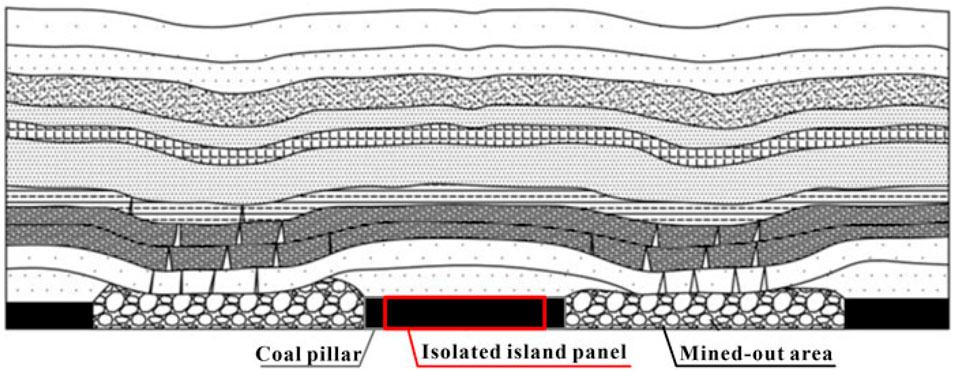
Figure 1. Underground mining schematic diagram.
Previous researchers deduced the expression for calculating the ultimate bearing capacity of rock-soil masses when plastic slip occurred during the pressure mold test. Combined with the characteristics of coal supporting pressure, the bearing limit (Pu) of the floor rock mass is obtained through appropriate modification, and its mathematical expression is presented by Equation 1:
where xa is the width of the plastic zone, m; C is the cohesion of rock mass, MPa; φ0φ0 is the internal friction angle of rock mass, °; and m is the stress concentration coefficient in front of the working face wall.
The slip site of the floor rock mass and the boundary of the plastic zone are shown in Figure 2. The plastic failure zone consists of three zones: active limit zone (aba’), transition zone (abc), and passive limit zone (acd). The slip lines in the active limit zone and the passive limit zone are composed of two groups of straight lines. One group of slip lines in the transition zone consists of logarithmic helices and the other is radiation from a. The logarithmic helix is expressed by Equation 2:
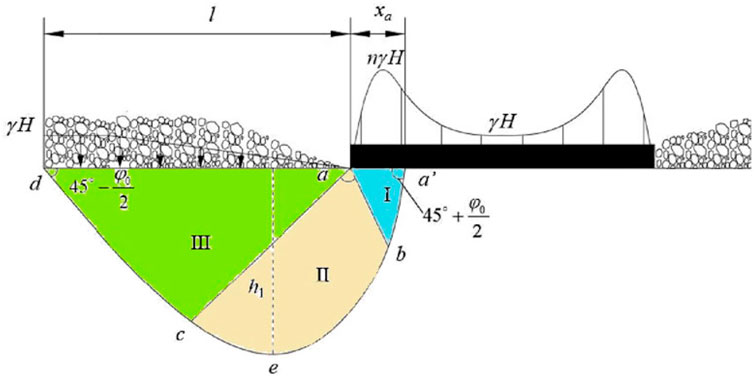
Figure 2. Plastic zone of the coal seam mining floor.
Figure 2 well explains the cause of the working face floor heave in the actual production. After coal seam mining, the supporting pressure is generated in the floor rock mass around the goaf. When the stress of the rock mass in the supporting pressure area (I) exceeds its ultimate strength, the rock mass will undergo plastic deformation, and this part of the rock mass will be compressed in the vertical direction, and the rock mass will inevitably expand in the horizontal direction. The expanding rock mass compresses the rock mass of the transition zone (II) and simultaneously transfers the stress to the zone. The rock mass in the transition zone continues to extrude the passive zone (III). Due to the free surface of the goaf in the passive zone, the stress exerted by the caving rock mass above the goaf floor is much lower than the original stress, making the rock mass in the transition zone and the passive zone expand into the goaf under the force transmitted from the active zone, which results in goaf floor expansion.
Based on the geometric size of the limit plastic zone shown in Figure 3, the maximum depth and length of the limit plastic failure zone under the supporting pressure of the coal edge can be determined.
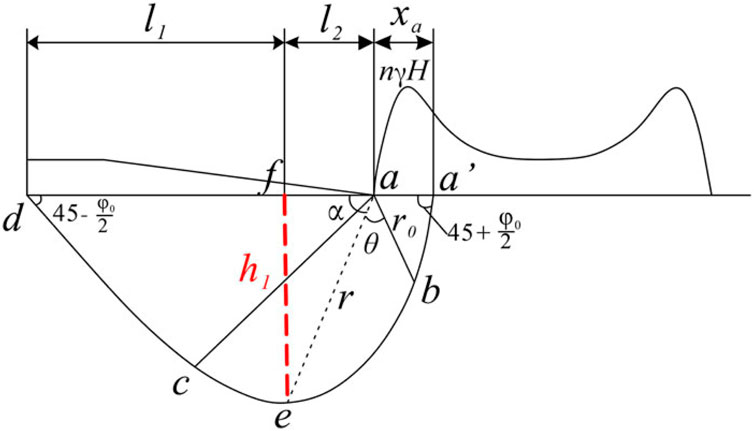
Figure 3. Schematic diagram for calculating the depth of the failure zone.
In terms of Δ∆ aba’,
For Δ∆ aef, the floor failure depth h = r✕sina, where
According to Equations 2–4, failure depth h of the panel floor can be expressed as
Equation 5 shows that the failure depth of the floor rock mass is related to θθ. Assuming that
By substituting Equation 6 and r0 into Equation 5, the maximum failure depth h1 of the floor rock mass can be obtained (Equation 7)
2.2 Floor stress analysis
To highlight the characteristics of the panel floor stress variation during coal mining in the isolated island areas, the numerical simulation method is applied, which compares the floor stress variation rule under the non-isolated and isolated mining conditions. In this study, COMSOL Multiphysics (CM) numerical simulation based on the finite-element method is widely applied in scientific research, engineering calculation, and industrial applications. As such, it can well explain the floor stress variation and water pressure acting on the panel floor. Two mining geological models are shown in Figures 4A, B.
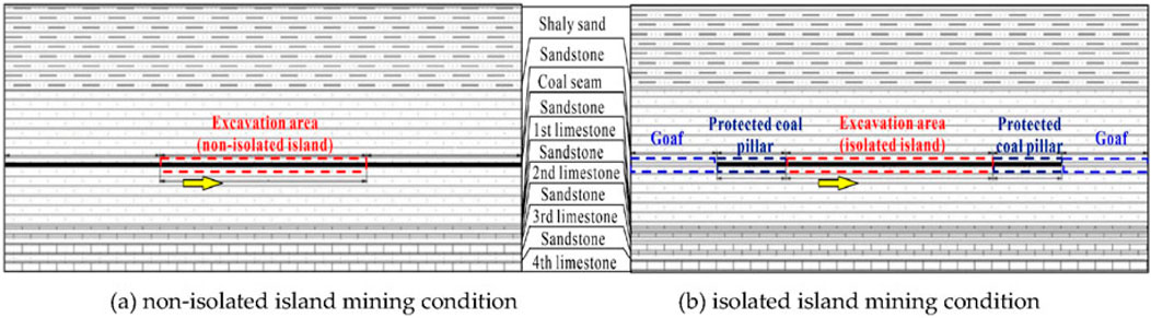
Figure 4. Mining geological models. (A) Non-isolated island mining condition and (B) isolated island mining condition.
The left and right boundary conditions of the models are set as roll support, the upper boundary is forced with a vertical load of 8.1 MPa, and the lower section of the models is constrained by a fixed boundary. Water pressure inside the aquifer can be used as the initial condition of seepage because of the recharge effect of the far-field water source on the water-bearing limestone. The water pressure of the right and left boundaries and the top boundary is set to 0 MPa, and the initial water pressure of seepage is set to 5.0 MPa at the bottom boundary.
The total mining length is 240 m for non-isolated and isolated island panels, the excavation step length is set to be 50 m, and the distribution law of the surrounding rock stress and floor water pressure in the mining stages are investigated as shown in Figures 5, 6. When there is no isolated island, coal mining facilitates the transfer of gravity of the overlying rock mass in the mined-out area to the coal pillar on both sides, resulting in stress concentration in the nearby coal pillar, and the bearing force increases. The surrounding rock stress near the goaf’s pillar is large and gradually tends to the normal stress. As the panel is mined, the concentrated stress on both sides increases, and the influence range of floor stress also increases.
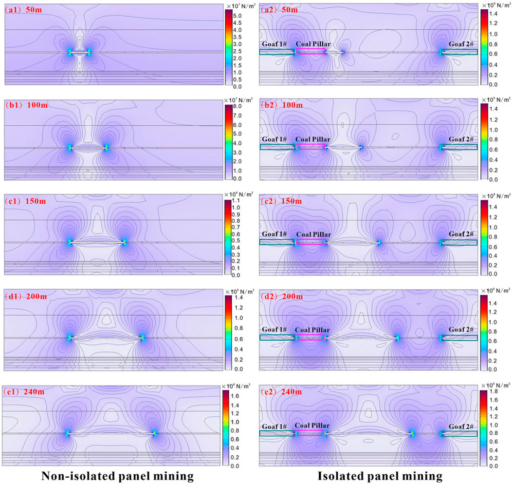
Figure 5. Mining stress variation cloud map comparing non-isolated (A1–E1) and isolated (A2–E2) panels.
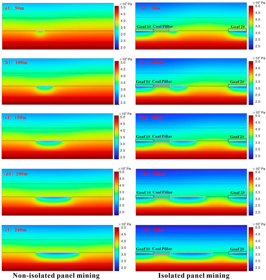
Figure 6. Water pressure variation cloud map comparing non-isolated (A1–E1) and isolated (A2–E2) panels.
When the mining length (before 100 m) is short, the floor water pressure is less. However, as the mining progresses, the water pressure increases, the influence range increases, and the water pressure depth increases. They easily cause the hydraulic connection between the panel with the floor aquifer and finally lead to water inrush into the gob.
Due to the formation of the mined-out area, the overlying load stress is redistributed. The stress of coal pillars on both sides of the mined-out area is concentrated, and the supporting force increases. Under normal mining conditions, the surrounding rock stress of the coal pillar near the goaf is large and gradually tends to the normal stress outward. For isolated mining, the isolated island area is more affected by the formation stress. The small stress is distributed on both sides of the panel floor, and the large stress in the middle is formed. The maximum stress of the floor is greater than that of the mined-out area under the non-isolated island. It can be seen that the strain and failure zone of the floor are larger, which increases the failure zone depth.
Generally, the water pressure of the broken floor in the goaf is smaller than that of the coal pillar, causing water inrush damage. The water pressure of the isolated island goaf floor is lesser, and it is more prone to water inrush damage. As the mined-out area of the isolated island increases, and the high-pressure water area is formed by the surrounding goaf, the water pressure disturbance range of the floor increases. As such, it is more prone to water inrush, and the threat of water outbursts is more serious.
2.3 Criterion of water inrush from the panel floor
Taking the Zhuzhuang colliery in the Huaibei mining area as an example, the theoretical derivation formula of the plastic slip line field, empirical formula, and industry-standard formula are together used to calculate the failure depth of the panel floor.
2.3.1 Plastic slip line field theory derivation formula
The coal seam thickness is 3.0 m, the maximum buried depth is 430 m, and the average bulk density of rock mass is γ = 24.90 kN/m3. The mechanical parameters of coal are listed as follows: cohesive force Cm = 3.11 MPa and internal friction angle φφ = 33.56°. When the maximum supporting pressure (pmax) of the working face front is 19.60 MPa, the maximum stress concentration coefficient n = pmax/γH = 1.8.
The expression of the width of the coal body plastic zone xa is as follows:
By substituting the above parameters into Equation 8, the width of the plastic zone at the edge of the coal body (xa) is 18.99 m. By substituting xa and the weighted average internal friction angle φ0φ0 of the panel floor rock mass into Equation 7, the maximum failure depth h1 of floor rock mass is obtained as 27.51 m.
2.3.2 Empirical equation
According to the empirical equation summarized by predecessors, it is expressed by Equation 9.
where H is the buried depth of the coal seam, m; a is the dip angle of formation, °; and L is the width of the working face, m.
The formation inclination is 8°, the buried depth of the coal seam is 430 m, and the panel width is 240 m, so the calculated value of the floor failure zone depth is 26.52 m.
The calculation results of the above two methods are contrasted. Considering the safety principle, the depth of the failure zone is 27.51 m.
2.3.3 Calculation of the height of the water-conducting fracture rising belt
Based on the theoretical calculation of the thin plate, the water-conducting fracture rising belt height of the panel floor is determined.
where calculation coefficient A is expressed as Equation 11:
In Equation 10 and Equation 11, H is the buried depth of coal seams, m; a is the dip angle, °; L is the inclined width of the panel, m; r is the average volume weight of the panel floor rock, MN/m3; p is the water pressure acting on the bottom of the waterproof layer, MPa; St is the tensile strength of the panel floor rock mass, MPa; and Ly is the first pressing step of the main roof of the panel along the advancing direction, m.
According to the specific engineering data, the water-conducting fracture rising belt height of the panel floor is calculated as 19.61 m.
As such, the thickness of the bottom protective layer is calculated as follows:
According to Appendix V of the “Rules for Water Control in Coal Mines,” the water inrush coefficient method is evaluated through Equation 12.
where T is the water inrush coefficient, MPa/m; P is the water pressure of the panel floor aquiclude, MPa; M is the effective thickness of the panel floor aquiclude, m.
When the water inrush coefficient is less than 0.06 MPa/m, the mining area belongs to the safe zone with pressure. The water inrush coefficient is between 0.10 MPa/m and 0.06 MPa/m, and the mining area belongs to the relatively safe zone with pressure. When the water inrush coefficient is greater than 0.10 MPa/m, the mining area belongs to the danger zone with pressure.
The water inrush coefficient T is calculated as 0.30 MPa/m, which is much higher than the water inrush coefficient of safe mining. Therefore, it is very dangerous to excavate coal seams under this condition, which would cause floor water inrush. It is necessary to implement the treatment measurements to eliminate the potential risk of the panel floor water outburst.
3 Prevention and control technique of water damage
3.1 Directional drilling technique
With the continuous upgrading of technical equipment, horizontal directional drilling for the grouting reinforcement method is often used to strengthen the water resistance of the aquicludes and reform the deep limestone aquifers. However, passing of directional drilling through the goaf, especially multiple goafs, easily results in problems such as well collapse, poor orientation, and complete slurry leakage. General grouting plugging means is difficult to play an effective role, so it is necessary to study a more targeted directional drilling technique to quickly pass through the goaf. To ensure the safe and rapid arrival of directional drilling to the target layer, some special technologies such as the casing cementing staged grouting isolation technique, the rapid crossing goaf technique, and the special mud and flexible drill pipe horizontal hole drilling technique are applied. Using these new techniques, the drilling work can be successfully completed in the complicated geology conditions.
3.1.1 Casing cementing staged grouting isolation technique
When the borehole passes through the mined-out area or close to the roadway, the four-opening structure is selected. The casing in the second opening is applied to isolate the mined-out area, and the bottom of the casing is 30 m away from the lowest mined-out area. The cementing is used to isolate the mined-out area. When the cementing process is completed, the casing pressure test is carried out. Before the borehole reaches the limestone layer, the section grouting is carried out on the floor failure zone of the goaf. The grouting is implemented to seal the vertical water-conducting cracks, including the primary cracks and mining-induced failure cracks. When the cracks are sealed well, directional drilling is used to expose the thin limestone layer.
When the thin layer of limestone is exposed by drilling and substantial leakage occurs, it is necessary to carry out grouting in a timely manner, and then we set the casing in the third limestone layer. Otherwise, the cementing quality of the three casing is poor. If the second section drills into the goaf or comes near the roadway, the subsequent drilling structure needs to adopt a four-opening structure; the drilling structure is shown in Figure 7.
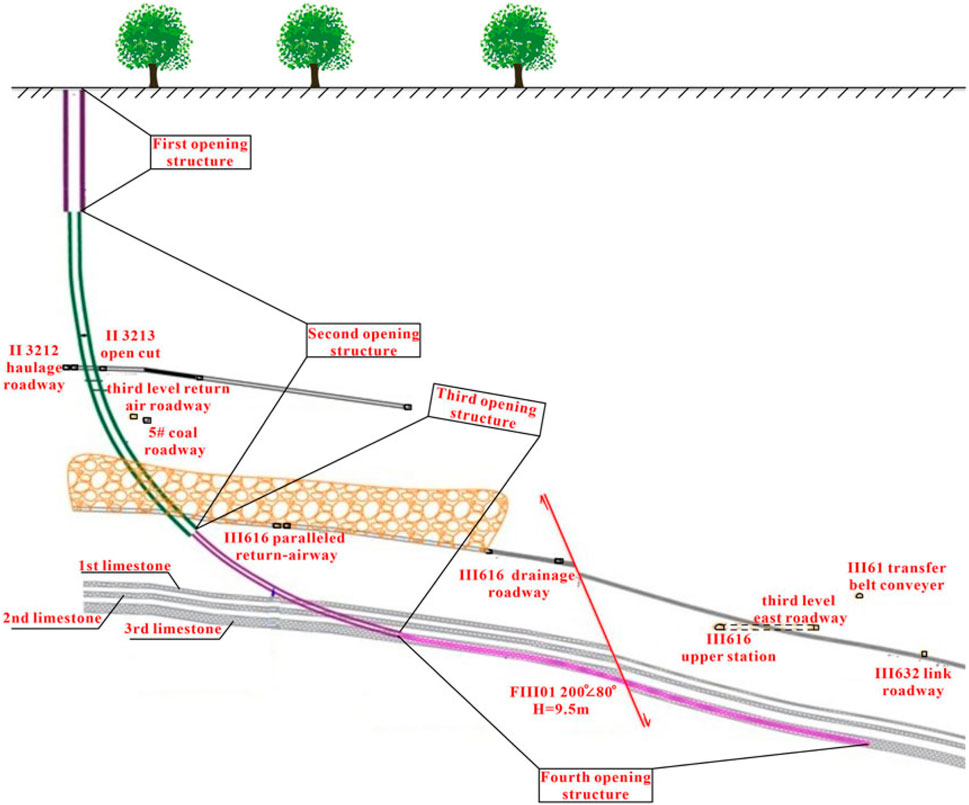
Figure 7. Schematic diagram of the four-opening hole structure section.
3.1.2 Rapid crossing goaf technique
To ensure that the directional drilling passes through the goaf quickly, two kinds of drilling techniques are adopted. First, when the drilling encounters a suspected goaf, the diamond middle-tooth PHYC drill bit dedicated to the fracture zone is used in order to pass through the goaf quickly. Second, when the passing of the borehole quickly through the goaf is observed to be difficult, the adjustment of mud slurry parameters is a key step for entering the goaf. The plugging material is added to reinforce the mined-out area by grouting and then drilling passes quickly. After passing through the mined-out area, the casing is run down, and staged grouting cementing is carried out to solve the borehole collapse problem.
3.1.3 Near-horizontal bedding drilling technique
In the near-horizontal section, a continuous mud tank, agitator, vibrating screen, mud remover, and other equipment are used to control the performance of sediment concentration and mud-cake for facilitating the optimization of mud slurry performance. Lubricants and inhibitors are added to make the drilling fluid obtain good lubricity inhibition and sand carrying potential. The friction coefficient of mud-cake is less than 0.1, the sand content is less than 0.5%, the low-density solid content is less than 12%, and the ratio of plastic viscosity and dynamic shear force of drilling fluid is not less than 2:1. Self-developed drilling fluid with good lubricity is used to maintain borehole stability in various rock formations, even in gravel rock and mudstone.
Meanwhile, the flexible drill pipe horizontal hole drilling technique is adopted in the near-horizontal section to prevent borehole collapse, bit sticking, and other accidents in the hole. The adopted drilling tool combination is “drill bit + power drilling tool + non-magnetic drill collar + non-magnetic short connection + drill string stabilizer + non-magnetic pressure-bearing drill pipe + heavy drill pipe + oblique shoulder drill pipe + vibration machine while drilling + drill pipe.” For construction in a high-strength medium hard limestone formation, Jianghan metal-sealed tri-cone insert bit and diamond medium-tooth PDC bit are selected.
The treatment modes of multi-layer limestone aquifers are as follows: 1) we use each branch hole of multiple hole groups to drill along the lower limestone aquifer, the hole spacing is not more than 60 m, and the treatment area is fully covered; 2) the secondary branch holes are opened by partial drilling of multiple hole groups, and 50 m is drilled into the upper limestone aquifer at the end of the bare hole in the lower limestone section, and the shallow upper limestone formation is curtained; 3) the underground drainage is carried out. Once the control technologies effectively facilitate reforming of the lower limestone aquifer, the hydraulic connection between the lower limestone aquifer and the working face is blocked, thus achieving the purpose of advanced treatment.
3.2 Grouting control technique
To ensure the control effect of high-pressure grouting under the goaf, the gradient pressurization grouting control technique and the segmented sequential downward grouting process are comprehensively utilized. During the grouting period, the well is linked up and down, and real-time scheduling and reasonable design of grouting pressure are applied; the construction of each borehole has a unique design, and the step-by-step, gradual gradient pressurized grouting method is implemented. Meanwhile, according to the pressure change and the relationship between the borehole and the roadway, the grouting process is adjusted in time to prevent the grouting from breaking through the roadway and the goaf; if there is underground slurry leakage, the grouting emergency plan is started through changing the grouting process and blocking the slurry leaking channel. Through-hole re-injection inspection is carried out. Based on the analysis of the characteristics of the thin limestone formation found under the panel, the gradient pressurized grouting control technique is applied to ensure the grouting effect, which is divided into four gradients: no pressure filling, micro pressure filling, pressure rising reinforcement, and high-pressure splitting, as shown in Figure 8.
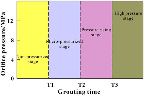
Figure 8. Gradient pressurization grouting control process.
3.2.1 Gradient pressurized grouting control technique
The gradient pressurized grouting control technique can effectively block the structural fissures, karst voids, and especially large-scale concealed vertical water-conducting channels. According to the analysis, the final grouting pressure of the gradient pressurized grouting control technique is generally 10–15 MPa.
3.2.2 Stepwise downward grouting process
The closed grouting process at the orifice and static pressure step-by-step downward grouting is adopted. In the treatment section, drilling and grouting are carried out in sequence based on the length of the unit grouting section. The length of the grouting section is adjusted based on the construction situation. The standard of grouting completion is not satisfied in the previous section, and the next section shall not continue to grout. Meanwhile, water pressure testing is carried out every 100 m during the construction process. If the injectability of the formation is low, the drilling is continued to 200 m for grouting.
4 Engineering application and treatment effect evaluation
4.1 Engineering application case
Taking the water disaster control of the coal pillar floor of the underground shaft in the Zhuzhuang colliery of Huaibei mining area as an example, the engineering application and effect of the regional treatment technique for isolated island mining in multi-layer goaf of deep resources are analyzed.
3#, 4#, 5#, and 6# coal seams are the minable coal seams in the Zhuzhuang colliery. With the continuous coal mining, the remaining reserves are not abundant, which makes it difficult to satisfy the need for coal yield in the future. To extend the service life of the mine, the mining range of the underground shaft coal pillar is delineated, as shown in Figure 9. The amount of 6# coal resources left in the shaft is 1.461 million tons, and the thickness of the coal seam is 2.33–3.26 m, with an average thickness of 2.80 m, which is the only remaining 6# coal resources. The coal pillar area of the underground shaft is shallow, and the panel floor karst structure is developed. The limestone water disasters threaten the excavation. The direct water-filling source is the limestone aquifer of the Taiyuan Formation under the working faces. A total of 11 water inrushes occurred around the three panels (II6122, III601, and II603) delineated by the underground shaft coal pillars. Among them, the water output was greater than 50 m3/h for six times, and the maximum water output was 1,400 m3/h.
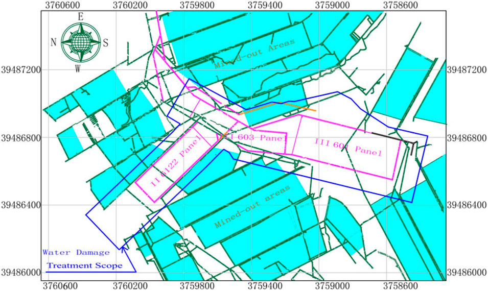
Figure 9. Plan layout of underground shaft panels.
Aiming at the problem of limestone water disaster in the underground shaft coal pillar floor, the idea of water prevention and control is to adopt the third limestone in the 60-m section of the panel to adopt the “regional full coverage advanced regional prevention”; the second limestone in the 30-m section of the extension of the working face above −420 m the “locking curtain treatment + internal key treatment”, and the “internal key treatment” are adopted in the section of the working face below −420 m. The layout of the working face and the scope of water disaster control are shown in Figure 9.
A total of 114 branch holes in seven main holes were constructed, with 56,234 m and a grouting volume of 276,891.15 tons. The full coverage treatment of the third limestone areas was completed, as well as the “lock curtain treatment + internal key treatment” in the shallow part of −420 m and the “internal key treatment” in the deep part of −420 m.
4.2 Treatment effect evaluation
4.2.1 Aquifer water level
The aquifer water level is one of the indexes to evaluate the regional treatment effect. If the water level of an aquifer remains normal, the hydrodynamic conditions around the borehole are good, and the aquifer fissures are developed. When the water level of the borehole is low and its recovery speed is slow, it implies that the water body around the borehole is dead water, the connection with the aquifers is weak, and the water-bearing fissures in the aquifer are not developed. When the water level of the borehole is high or even “overflows,” indicating that a closed space exists around the borehole, the phenomenon of pressure accumulation occurs. The high water level of “overflows” will occur due to the high-pressure grouting in the surrounding area. Grouting operation fills most fracture channels, changes the groundwater flow, and forms a local high-pressure concentration area, indicating that the fracture channels are well-sealed. At the end of each segmented drilling construction, the aquifer’s water level was observed when the cycle drilling was started.
There were 77 branch holes in the horizontal section of the third limestone aquifer. The water level observation and distribution of the third limestone aquifer are shown in Figure 10. The water level ranged from −105.67 m to the return water of the orifice. The water level of the third limestone aquifer was generally +10 m through the ground hydrological long-term observation holes in the same period. Due to the relatively shorter observation time of the directional horizontal borehole water level, the recovery speed of the borehole water level was relatively slower. Therefore, the water level elevation of the borehole was divided into different intervals to judge the water level accurately, namely, the normal water level ranged from 0 m to +12 m; the low water level was less than 0 m; and the overflow water level was greater than +12 m.
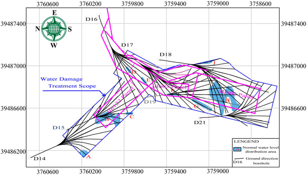
Figure 10. Water level plan of the third limestone aquifer.
As can be seen from Figure 10, most of the water levels were low water level and overflow water level, indicating that the grouting effect in these areas was good. The normal water level was distributed in nine regions, which were numbered A, B, C, D, E, F, G, H, and I, respectively. According to the causes of the normal water level, the nine regions can be divided into three types: the first exposure type, the sporadic type, and the centralized type. Among them, the first exposure type included F and G areas, the sporadic type included A, C, D, E, and J areas, and the concentrated type included B and H areas.
There were 37 branch holes in the horizontal section of the second limestone aquifer. The water level observation and distribution of the second limestone aquifer are shown in Figure 11. The water level ranged from −200 m to the return water of the orifice. The water level of the second limestone aquifer was generally +17.4 m through the surface hydrological long-term observation holes in the same period. According to the change of water level elevation, it was divided into different intervals, which are divided into normal water level (+7–+18 m), low water level (≤+7 m), and overflow water level (≥+18 m).
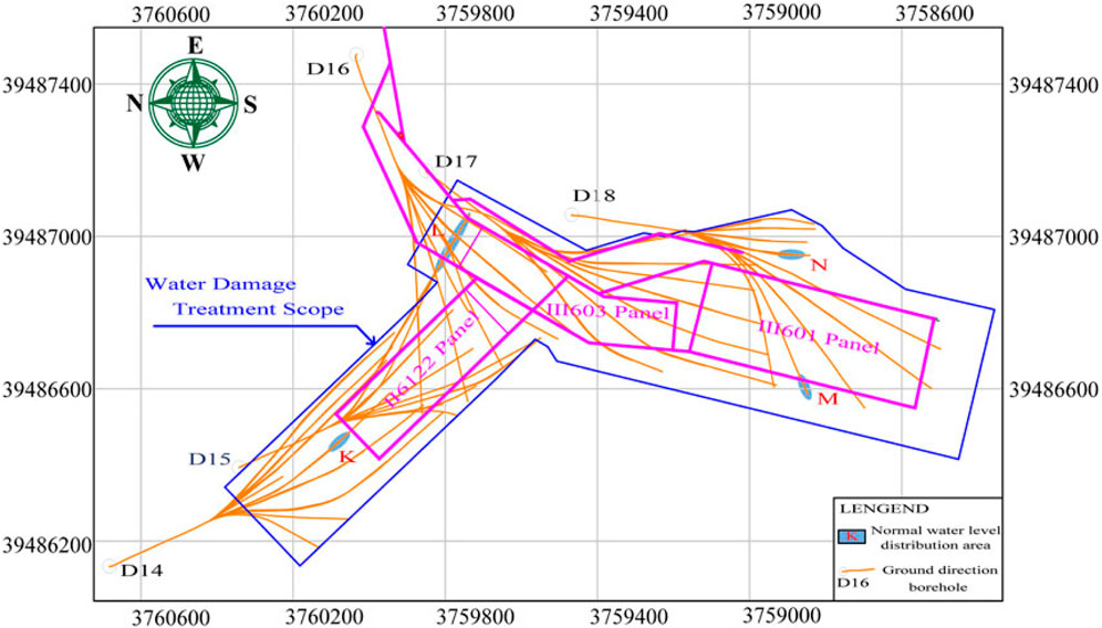
Figure 11. Water level plan of the second limestone aquifer.
As can be seen from Figure 11, the water level in most areas was low, and some areas were overflow areas, indicating that the grouting effect in these areas was good. The normal water level was distributed in four regions, numbered K, L, M, and N. According to the causes of the normal water level, the four normal water level regions were sporadic.
4.2.2 Underground drilling verification
Underground directional holes were applied to verify the regional treatment of underground vertical shaft for the second and third limestone aquifers. Directional drilling was carried out in the drilling field of the three-level east roadway, III 62 return airway, and III 63 winch combined roadway. The verification drilling layout and construction of the second and third limestone aquifers’ treatment are shown in Figures 12, 13.
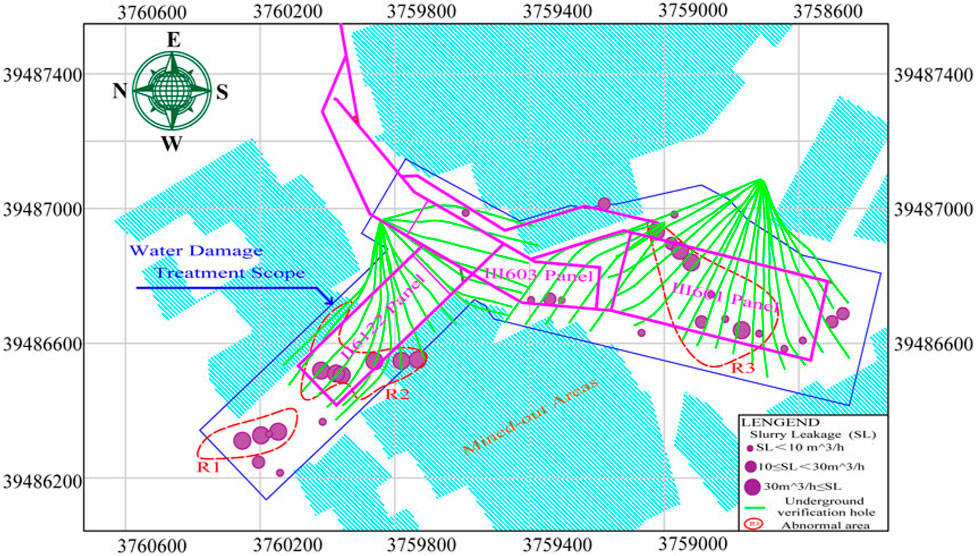
Figure 12. Underground drilling verification for the third limestone aquifer.
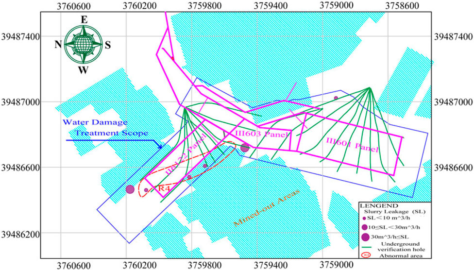
Figure 13. Underground drilling verification for the second limestone aquifer.
A total of 19 verification boreholes for the third limestone aquifer and nine verification boreholes for the second limestone aquifer were designed in the three-level east roadway, and the total drilling length was 14,876.5 m. It was verified that most of the boreholes had no water, and the maximum stable water output was only 1.8 m3/h. The water yield of the boreholes under construction for the second limestone aquifer was also less, and the maximum water yield currently was 2.4 m3/h, indicating that the treatment effect was good within the verification area.
A total of 18 verification boreholes for the second limestone aquifer and nine verification boreholes for the second limestone aquifer were designed in the III 62 return airway. At present, 12 boreholes have been completed, the drilling length is 6,361 m in total, the maximum amount of drilling water is 2.0 m3/h, and the water yield is further attenuated, indicating that the treatment effect is good.
A total of five verification boreholes for the thirrd limestone aquifer and two verification boreholes for the second limestone aquifer were designed in the III 63 winch combined roadway, with a project amount of 3,590 m. Two boreholes (cumulative length of 860 m) that have been constructed are anhydrous.
In short, after the verification of the water yield of the underground boreholes, and after the ground regional treatment, the third and second limestone formations under the III601 panel were anhydrous, and the key verification area (R3) had a better treatment effect. II6122 and III603 panels were verified. It showed that the comprehensive key verification area (R2) had a good control effect. The next stage will further verify the treatment effect of the third and second limestone formations in other regions. The comprehensive key verification area (R1) is located outside the range of the adjusted panels, which does not affect the safe production of the panel.
5 Conclusion
With the depletion of coal reserves under high intensity and large-scale mining, the liberation of the coal resources left in isolated islands is an optimal choice to solve the production troubles. In this study, the water inrush mechanism of the high-confined pressure limestone aquifers under the isolated island panels is mastered through theoretical mechanical analysis and numerical simulation. Four-open drilling structures, stepwise gradient pressurization, and segmented sequential downward grouting techniques are proposed. Then, the limestone water hazard prevention technique is proposed and illustrated using the actual engineering case. Accordingly, the data from the water level observation and underground directional borehole inflow validate the regional treatment effect. Based on these studies, the following conclusions are drawn:
(1) The maximum failure depth of the isolated island panel floor is determined. Taking the Zhuzhuang colliery as an example, the maximum failure depth of the coal seam floor is found to be 27.5 m, and the thickness of the water-resisting protective layer is only 13.87 m. The water inrush coefficient of the limestone aquifer on the panel floor is 0.3 MPa/m, exceeding the critical water inrush coefficient (T0 = 0.6 MPa). Therefore, there is a risk of the panel floor water inrush in island coal seam mining.
(2) The casing cementing segmented grouting isolation technique, rapid crossing goaf technique, and special mud flexible drill pipe horizontal well drilling technique are proposed to ensure the safe and rapid arrival of directional drilling to the target layer. The treatment mode of multi-layer limestone aquifers is as follows: using each branch hole of multiple hole groups to drill along the lower limestone aquifer, the hole spacing is less than 60 m, and the treatment area is fully covered; the secondary branch holes are opened by partial drilling of multiple hole groups, and 50 m is drilled into the upper limestone aquifer at the end of the bare hole in the lower limestone section, and the shallow upper limestone aquifer is curtained, and then the underground drainage is carried out.
(3) Through the borehole water level observation during the drilling period and the water output of the limestone aquifer exposed by the underground directional boreholes, the grouting effect of the limestone aquifer in the isolated island panel floor is evaluated. Based on the water level change, it is divided into normal water level, low water level, and overflow water level. Most of the areas are characterized by low water level, and some areas are overflow areas. In terms of underground directional drilling construction in the second and third limestone aquifers, the water yield is small (the maximum water yield is below 2.5 m3/h), thus further verifying the grouting treatment effect is better.
Despite that the drilling machinery equipment has been greatly improved than before, the grouting material is used more in conventional concrete cement or concrete mixed with fly ash. The modified materials with high fluidity and high strength after solidification need to be developed to improve the grouting quality. In addition, before the implementation of grouting treatment, high-precision water hazard detection should be carried out to find out the scope affected by water outbursts and to make the target area clear.
Data availability statement
The original contributions presented in the study are included in the article/Supplementary Material; further inquiries can be directed to the corresponding author.
Author contributions
WW: methodology, software, supervision, and writing–original draft. YW: formal analysis, visualization, and writing–original draft. YS: data curation, validation, and writing–review and editing. JZ: investigation and writing–review and editing.
Funding
The author(s) declare that financial support was received for the research, authorship, and/or publication of this article. This research was funded by the Fundamental Research Funds for the Central Universities (No. 2023XSCX003).
Conflict of interest
Authors WW, YW, and YS were employed by CCTEG Xi’an Research Institute (Group) Co., Ltd.
The remaining author declares that the research was conducted in the absence of any commercial or financial relationships that could be construed as a potential conflict of interest.
Generative AI statement
The author(s) declare that no Generative AI was used in the creation of this manuscript.
Publisher’s note
All claims expressed in this article are solely those of the authors and do not necessarily represent those of their affiliated organizations, or those of the publisher, the editors and the reviewers. Any product that may be evaluated in this article, or claim that may be made by its manufacturer, is not guaranteed or endorsed by the publisher.
References
Cao, Z., Jia, Y., Li, Z., and Du, F. (2023). Research on slurry diffusion and seepage law in mining overburden fractures based on CFD numerical method. Sci. Rep. 13, 21302. doi:10.1038/s41598-023-48828-5
Chai, J. (2022). Investigation of spontaneous combustion zones and index gas prediction system in goaf of “isolated island” working face. Fire 5, 67. doi:10.3390/fire5030067
Du, F., Li, Z., Li, S., Li, X., Li, G., Fan, X., et al. (2024). Breaking law of overburden rock and key mining technology for narrow coal pillar working face in isolated island. Sci. Rep. 14, 13045. doi:10.1038/s41598-024-63814-1
Feng, G., Bai, J., Ma, J., Guo, J., Pan, R., Wang, K., et al. (2023). Technical challenge of coal pillars resource green mining and underground space developing in the residual mining area. J. Green Mine 1, 91–100.
Han, C., Yang, H., Zhang, N., Deng, R., and Guo, Y. (2021). Zoning control technology of gob-side roadway driving with small coal pillar facing mining in a special isolated island working face: a case study. Appl. Sci. 11, 10744. doi:10.3390/app112210744
Hou, Z., Yang, S., Shao, H., Zhou, B., Cai, J., and Miao, J. (2023). Identification of zones with coal spontaneous combustion hazards in the three goafs surrounding an isolated island working face: a case study on Qianyingzi Coal Mine. Combust. Sci. Technol. 195 (12), 2820–2842. doi:10.1080/00102202.2022.2041001
Jia, C., Lai, X., Cui, F., Xu, H., Zhang, S., Li, Y., et al. (2024). Mining pressure distribution law and disaster prevention of isolated island working face under the condition of hard “umbrella arch.”. Rock Mech. Rock Eng. 83, 8323–8341. doi:10.1007/s00603-024-03961-z
Krasnovyd, S., Konchits, A., Shanina, B., Valakh, M., Yukhymchuk, V., Skoryk, M., et al. (2023). Coal from the outburst hazardous mine seams: spectroscopic study. Min. Min. Depos. 17 (1), 93–100. doi:10.33271/mining17.01.093
Lan, T., Liu, Y., Yuan, Y., Liu, H., Liu, H., Zhang, S., et al. (2023). Mine pressure behavior law of isolated island working face under extremely close goaf in shallow coal seam. Sci. Rep. 13, 20576. doi:10.1038/s41598-023-47907-x
Li, X., Song, B., and Li, P. (2019). Study on optimization of mining pillar in isolated island working face of thick coal seam under complex conditions. IOP Conf. Ser. Earth Environ. Sci. 252, 052150. doi:10.1088/1755-1315/252/5/052150
Liu, H., Wang, P., Zhang, W., Liu, Q., and Su, L. (2020). Comprehensive measurement of the deformation and failure of floor rocks: a case study of the Xinglongzhuang coal mine. Geofluids 2020, 1–14. doi:10.1155/2020/8830217
Long, Z. (2023). Microseismic positioning of an isolated working face under complex geological conditions and its engineering application. Front. Earth Sci. 10, 1043790. doi:10.3389/feart.2022.1043790
Ma, L., Du, S., He, C., Guo, R., and Tao, W. (2023). Air leakage law and prevention technology of coal spontaneous combustion in the goaf of “isolated island” fully mechanized caving face. Combust. Sci. Technol. 196 (15), 3418–3437. doi:10.1080/00102202.2023.2175611
Qi, H., and Yu, J. (2018). Rationality and comprehensive unloading technology of deep high stress section coal pillars. J. China Coal Soc. 43 (12), 3257–3264. doi:10.13225/j.cnki.jccs.2018.0394
Shi, L., Zhang, J., Lu, W., Lv, D., and Sun, X. (2023). Study on roadway layout and surrounding rock control of isolated island panel. Sci. Rep. 13, 19637. doi:10.1038/s41598-023-46664-1
Soleimani, F., Si, G., Roshan, H., and Zhang, J. (2023). Numerical modelling of gas outburst from coal: a review from control parameters to the initiation process. Int. J. Coal Sci. Technol. 10, 81. doi:10.1007/s40789-023-00657-7
Wang, P., Zhao, Y., Ren, Q., Jiang, Y., Zhang, C., and Gao, Y. (2022). Floor failure characteristics in deep island longwall panel: theoretical analysis and field verification. Geofluids 2022, 1–14. doi:10.1155/2022/1851899
Wang, Y., Chen, P., and Wang, S. (2023). Study of overlying rock structure and intensive pressure control technology of island longwall panel in extra-thick coal seams. Processes 11, 3083. doi:10.3390/pr11113083
Wen, Y., Cao, A., Guo, W., Xue, C., Lv, G., and Yan, X. (2023). Strata movement and mining-induced stress identification for an isolated working face surrounded by two goafs. Energies 16, 2839. doi:10.3390/en16062839
Yun, Q., Wang, X., Jing, W., Zhang, W., Wei, X., and Wang, J. (2024). Characteristics of deformation and damage of surrounding rock along the top roadway in the working face of an isolated island and its evolution law. Sci. Rep. 14, 15092. doi:10.1038/s41598-024-63246-x
Keywords: isolated islands, water inrush, floor failure, drilling technique, grouting effect, regional treatment
Citation: Wang W, Wu Y, Shi Y and Zhu J (2025) Outburst mechanism and hazard prevention technique of limestone aquifer under isolated island panels. Front. Earth Sci. 12:1532515. doi: 10.3389/feart.2024.1532515
Received: 22 November 2024; Accepted: 30 December 2024;
Published: 30 January 2025.
Edited by:
Manoj Khandelwal, Federation University Australia, AustraliaReviewed by:
Merghadi Abdelaziz, University of Tébessa, AlgeriaVasyl Lozynskyi, Dnipro University of Technology, Ukraine
Copyright © 2025 Wang, Wu, Shi and Zhu. This is an open-access article distributed under the terms of the Creative Commons Attribution License (CC BY). The use, distribution or reproduction in other forums is permitted, provided the original author(s) and the copyright owner(s) are credited and that the original publication in this journal is cited, in accordance with accepted academic practice. No use, distribution or reproduction is permitted which does not comply with these terms.
*Correspondence: Jingzhong Zhu, YWxnemp6MDgwMUAxMjYuY29t