 Qingyuan Yang
 Song Chen
- 1School of Architecture and Engineering, Guangzhou Panyu Polytechnic, Guangzhou, China
- 2Hebei Center for Ecological and Environmental Geology Research, Hebei GEO University, Shijiazhuang, China
The thickness of aquifer is relatively large, the aquifer is not completely isolated by the diaphragm wall, and the water flow inside and outside the foundation pit flows at the bottom of the diaphragm wall. This article reports indoor experiments and theoretical methods which are used to study the deformation mechanism and law caused by dewatering in foundation pit under the condition of incomplete isolation of the inner and outer aquifers of the foundation pit based on typical geological conditions in South China. Our findings are as follows. (1) Through the experimental analysis of the mechanism of groundwater seepage around the foundation pit, the effective influence depth of precipitation in the foundation pit is greater than that outside the foundation pit, and the effective influence depth of double well precipitation is greater than that of single well precipitation. It reveals that the precipitation curve outside the foundation pit under the influence of seepage around the foundation pit presents the characteristics, and puts forward the calculation formula of surface settlement change outside the pit caused by partially penetrating well precipitation in the completely decomposed granite stratum. The calculation results of the theoretical formula are in good agreement with the experimental results, which has good accuracy and applicability. (2) The surface settlement outside the pit caused by dewatering in the foundation pit is mainly concentrated in the surrounding seepage area, and the change value of surface settlement outside the pit caused by double well dewatering is 2∼3 times greater than that caused by single well dewatering. When the whole well is vertically reinjected, the maximum surface settlement is 0.009 mm at the side near the diaphragm wall, and 0.005 mm at the side far away from the diaphragm wall. When the whole well is at an inclination of 10°, the maximum surface settlement is 0.002 mm at the side near the diaphragm wall, and 0.008 mm at the side far away from the diaphragm wall. When the whole well is at an inclination of 20°, the maximum surface settlement is −0.005 mm at the side near the diaphragm wall, and 0.011 mm at the side far away from the diaphragm wall. The full well depth recharge with an inclination of 20° has the largest influence on the surface settlement of the foundation pit, and the recharge effect is the best. (3) The lateral displacement of diaphragm wall increases by 24% compared with that without reinjection. The maximum lateral displacement of the diaphragm wall is 0.09% of the precipitation depth when the whole well is tilted at 10° for reinjection, and the lateral displacement of the diaphragm wall increases by 13% compared with that without reinjection. The maximum lateral displacement of the diaphragm wall is 0.082% of the precipitation depth when the whole well is tilted at 20° for reinjection, and the lateral displacement of the diaphragm wall increases by 4.9% compared with that without reinjection. The full well depth recharge with an inclination of 20° has the least impact on the diaphragm wall, and the recharge effect is the best. The above results can be provided as theoretical foundation for the study of the deformation mechanism and law caused by dewatering in foundation pit.
1 Introduction
In recent years, with the increase in depth and quantity of foundation pit engineering, the degree of foundation pit dewatering will also increase, and the impact of foundation pit dewatering on the deformation of surrounding soil will become more prominent. At present, domestic and foreign scholars have achieved certain results in the research of deformation mechanisms and laws caused by foundation pit dewatering.
Based on the Pasternak elastic foundation beam theory, combined with the effective stress principle of soil and the Dupuit hypothesis Xu et al. (2021) derived the analytical solution of adjacent pipeline deformation in sandysoil caused by single well dewatering, based on the Pasternak model of elastic foundation beams, and combining the effective stress principle of soil and Dupuit hypothesis, The example calculation results are in good agreement with the results of pumping test and numerical simulation, which verifies the applicability. The law of stress and deformation for the pipeline is studied by parameter analysis. The results show that the influence of soil shear stiffness should not be ignored in the study of soil pipeline interaction and the pipeline deformation range is approximately equal to the influence radius of dewatering. Pipeline deformation and stress are greatly influenced by dewatering depth and the distance between the pipeline and the dewatering well, Before reaching the critical drawdown, the maximum value of pipeline deformation and bending moments are at the center of pipeline, increasing with the increase of dewatering depth. Lv et al. (2020) derived analytical expressions for stable flow in ancient river channels under pressure and intact wells under pressure. Based on this, apply it to foundation pit dewatering engineering and propose a method for calculating the water inflow of foundation pits in confined aquifers of ancient river channels. On this basis, it is applied to the foundation pit dewatering project, and a method for calculating the water inflow of the foundation pit of artesian aquifers in the ancient river is put forward. Taking the deep foundation pit of the underground parking lot of Liyuan Plaza in Wuhan as an example, the calculated results are compared with those of the traditional methods and the actual monitoring data. The results show that the relative error between the calculated results andthe actual water inflow of the foundation pit is only 7.4%. While the relative error of the traditional method is 54.5%. Which verifies the rationality of the proposed method. Based on the principle of continuity of groundwater seepage and combined with Darcy’s law, Zhang et al. (2021) proposed a calculation method for surface settlement considering suspended water stop curtains, and established a complete optimization method for water control design of suspended water stop curtains that considers both safety and economy in foundation pit design. Finally, an applicable procedure of dewatering of foundation pit with waterproof curtain partially penetrating aquifers was developed. in which water control cost is set as the target, and ground subsidence and groundwater inflow are set as the constraints conditions considering both safety and economy of foundation pit design. Shi et al. (2022) established a three-dimensional numerical model of seepage stress coupling based on the research background of subway deep foundation pits in a water rich geological environment, and studied the deformation and displacement process of deep foundation pits after precipitation and the influencing factors under different precipitation conditions. The results show that during the dewatering and excavation of foundation pits, seepage-stress has an obvious coupling effect in dewatering and excavation. The stress concentration position of retaining structure and the maximum displacement of lateral displacement are about 0.5–0.6 excavation depth of pile body. With the depth of precipitation increases, the seepage effect in the soil layer is obviously enhanced, which is not conducive to the stability of the foundation pit. Xu et al. (2022) analyzed the causes of seepage accidents in foundation pits and found potential weak areas formed by three-axis mixing piles and abandoned piles, and reinforced the foundation pit to control groundwater. The seepage failure was attributed to the defects in the three-axis mixing piles and the potential weak region created around the abandoned pile. It was finally controlled by filling the whole foundation pit with water. A systematic reinforcement of the foundation pit was carried out. The soil disturbed by the seepage failure was reinforced by two-shot process grouting and sleeve valve pipe grouting. The cast-in-place piles and prestressed assembled steel struts were constructed to strengthen the original retaining wall and support system. Yuan et al. (2013) proposed an estimation method for ground settlement caused by precipitation under lateral friction constraint. The research results show that the constraint function of lateral friction to soil settlement is mainly limited in the range of 18 m away from the waterproof curtain; the position where the constraint effect of lateral friction became most significant was at the interface of soil and waterproof curtain, The novel estimation method proposed taking the lateral friction into account can well predict the space distribution of soil subsidence induced by dewatering. Wu and Zhu (2016) proposed a calculation method for ground settlement caused by foundation pit precipitation considering the influence of unsaturated soil in the drainage zone. By ignoring the lateral displacement and the effect of the group wells, the effective stress principle of unsaturated soil was induced and the equation of the water-table depression was solved on the supposition of Dupuit presupposition. Then the settlement of the soil layers above and below the cone of water-table depression was calculated respectively based on the layer-wise summation method, and the actual settlement was the sum of them. Comparison of numerical simulation results with monitoring results of the engineering examples show that the calculation method is of practical engineering value.
Debasis and Keith (2009) conducted a study on ground settlement caused by bedrock drainage in soft soil sites. Subsurface investigation and monitoring data obtained over 5.75-year period following the construction of the structure indicated that the settlement resulted from consolidation of soft soils due to depressurization of an aquifer within the underlying bedrock caused by continuous dewatering needed for the operation of the structure. An analytical study was undertaken to project the long term settlement. Li et al. (2008) proposed a simplified algorithm for calculating ground settlement caused by drainage in foundation pits. When the lateral displacement is ignored, the layer-wise summation method can be used to calculate the settlement, The equation of the cone of water-table depression was obtained on the supposition of Dupuit presupposition, so the increment of effective stress of the soil layers above and under the cone of water-table depression could be calculated, then the settlement could be calculated by the layer-wise summation method. The restriction to the settlement by diaphragm (pile) was also taken into account, the settlement influenced by the restriction of the diaphragm (pile) was calculated by use of the relationship of the shear-displacement on the experiential assumption, and the actual settlement was the sum of the both. The settlement of a foundation pit was obtained, showing that the simplified analysis is feasible. Huang and Lu (2009) proposed an evaluation method for ground settlement caused by foundation pit precipitation in specific areas. With the method and data from the construction site of Yizhuang light railway, the optimum values of the storage coefficients of elastic and non-elastic aquifers of the site are determined, respectively. Further, with the storage coefficients and an effective stress analysis method, the land subsidence tendency of the construction site of Yizhuang light railway is evaluated. The results show that the southeastern part of the construction site will subside as large as 70–126 mm in the next 10 years (2006–2015) if the situation of groundwater extraction is not improved. Wang et al. (2009) proposed a calculation method for ground settlement induced by deep foundation pit precipitation in subway stations. Firstly, the single point deformation and compression in each layer are defined according to the law of inversed rebound, supposing that the inversed rebound and consolidation appear simultaneously but can be calculated separately; and the inversed rebound is measured by inversed rebound index. And the gradual consolidation is considered by layer division. When the inversed rebound value is greater than consolidation one, the strata willexpand. The ground subsidence can be precisely predicted by the method when the inversed rebound index anddrawdown are measured or calculated reasonably. Zhang (2014) studied the characteristics and laws of groundwater seepage field in suspended water curtain foundation pits. Liu (2016) studied the effects of factors such as interlayer permeability, head difference, and aquifer thickness on the seepage field of layered aquifers. Liu (2002) explores the feasibility of introducing the concept of “effective zone” for pumping and transforming the calculation of partially penetrating well group water inflow into an equivalent complete well group water inflow calculation method. Several examples indicate that simplified method can control the comparative error of the discharge of one pit within 20 percent, then prove that the simplified method to a certainly has practical value. Jia et al. (2016) established calculation models for soil deformation caused by single well pumping and insertion of waterproof curtains into dewatering aquifers under displacement coordination conditions. The analytical results show that elastic modulus of the overlying soil has little influence on ground surface displacement, yet thickness of overlaying soil layer shall be taken into consideration. The settlement of soils overlying confined aquifer increases up to down nearby the pumping well. Over a certain distance, the settlement does not change with depth. The drawdown outside the foundation pit can be estimated according to the demand for drawdown inside the foundation pit. Wang et al. (2015) analyzed the seepage characteristics of the flow and non flow zones formed under the influence of suspended curtains, and systematically proposed the modified large well method for calculating the inflow of groundwater and confined water under suspended curtain conditions. Luo et al. (2004) derived a formula for calculating the settlement consolidation degree caused by pressure reduction under the assumption of one-dimensional vertical consolidation. Gong and Zhang (2011) and Wang et al. (2013) proposed a formula for calculating additional distributed internal forces considering the pressure reduction effect of confined water based on the complete well theory, and derived a formula for calculating surface settlement considering the additional distributed internal forces of pressure reduction effect of confined water. By calculating steady flow of fully penetrated well of confined water, the additional force acting on the overlaying soil, which is caused by pressure-relief of confined water, is studied. Above all. The effects of some parameters on the settlement are studied, such as the thickness, modulus of the overlaying soil, head difference and transmissibility of the confined aquifer. Through an example, the settlement of the ground caused by decompression of confined water is small and agrees with the actual one. Zheng et al. (2013) used an asymmetric foundation pit project as a research example, established a numerical model, and simulated and analyzed the deformation characteristics of the foundation pit enclosure structure caused by step-by-step dewatering excavation. Due to different excavation depths of the asymmetric foundation, in the process of staged dewatering and excavation, the vertical deformation of the retaining structure is inclined along the cross-section. In the meantime, the horizontal deformation goes towards the direction of the shallow pit, which makes the eccentric rotation of the whole retaining structure. Liu et al. (2013) used transient analysis to simulate the process of foundation pit dewatering and analyzed the impact of foundation pit dewatering on the foundation pit support system and surrounding environment. Wu et al. (2012) analyzed the influence of considering groundwater seepage on the embedded depth of multi-layer support and enclosure structures in soft soil areas, revealing the importance of considering seepage in the analysis of excavation deformation and internal forces of foundation pits. The proposed controlling index to determine the embedded depth is put forward. Combined with the monitoring results, a conclusion on whether to consider the effect of seepage flows in the excavation deformation and stress analysis is drawn. Zhang et al. (2010) analyzed the monitoring data of the steel support axial force, horizontal displacement, surrounding groundwater level, and surface settlement of the enclosure structure, and obtained the variation patterns of relevant parameters. The precipitation of tube wells supported by light wells and waterproof curtain walls successfully resolves the potential hazards posed by high-pressure water. According to the analysis of monitoring data of horizontal displacements, axial forces, surface settlements and water levels, some useful variations of the parameters are obtained, and they can be used as references for the design and construction of similar projects. Ran and Hu (2009) studied the effects of factors such as soil density, internal friction angle, cohesive force, friction characteristics between retaining piles and soil around foundation pits, as well as the depth of insertion of foundation pit retaining structures into soil layers, on the infiltration failure mode and critical hydraulic gradient. Chen et al. (2008) analyzed the main reasons for changes in the surrounding environment caused by foundation pit dewatering during construction, and designed a partition pressurized water treatment plan. Through a case in Kunshan area, the causes for the influence of dewatering of the deep foundation pit on the surrounding environment were analyzed. The design for cutting off the confined water was analyzed, and a repair project was advanced. The results are of some directive significance for the design of the deep foundation pit.
These scholars have conducted research on the mechanism or pattern of deformation caused by precipitation inside and outside the foundation pit based on the Dupuit theory of precipitation curve. In fact, when the thickness of the aquifer is large and there is precipitation inside the foundation pit, due to economic and technical limitations, the connecting wall cannot completely isolate the aquifer inside and outside the foundation pit. There is a phenomenon of seepage at the bottom of the connecting wall, and groundwater will move horizontally and vertically, resulting in differences between the actual precipitation curve outside the pit and the Dupuit theory precipitation curve form, which affects the accuracy of analyzing the deformation mechanism or law caused by precipitation inside the pit based on the Dupuit theory precipitation curve. It can be seen that studying the deformation mechanism and laws caused by precipitation in the foundation pit is of great practical significance for the seepage situation at the bottom of the diaphragm wall.
This article takes the foundation pit project of a subway comprehensive hub in South China as the background, selects typical strata in South China, and uses design model tests and theoretical analysis to reveal the mechanism of water level changes outside the foundation pit caused by partially penetrating well precipitation. It proposes a calculation method for the precipitation curve outside the pit and the division of seepage zones, and then proposes a simplified calculation method for surface settlement outside the foundation pit. At the same time, the laws of surface settlement outside the pit and deformation of the diaphragm wall caused by different forms of precipitation and recharge were studied.
2 Engineering background
The model test is based on a subway foundation pit project in South China. The strata within the excavation area are typical phreatic aquifer, which are distributed from top to bottom as a layer of silty clay, conglomerate clayey soils, completely decomposed granites, and strongly weathered granites. The physical and mechanical parameters of the actual strata related to dewatering and surface subsidence are shown in Table 1.
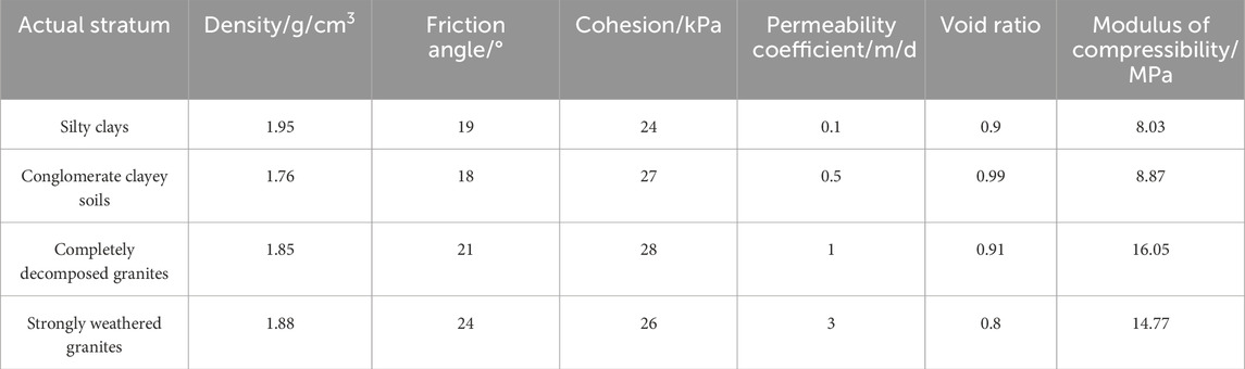
Table 1. The physical and mechanical parameters of the actual strata.
3 Research on the effective influence depth of partially penetrating wells
3.1 Experimental process
The layout plan and section of the partially penetrating wells dewatering model test in the foundation pit are shown in Figure 1. Yang et al. (2023) and Wu et al. (2022), Wu et al. (2024) provided the testing method and steps for the foundation pit dewatering model.
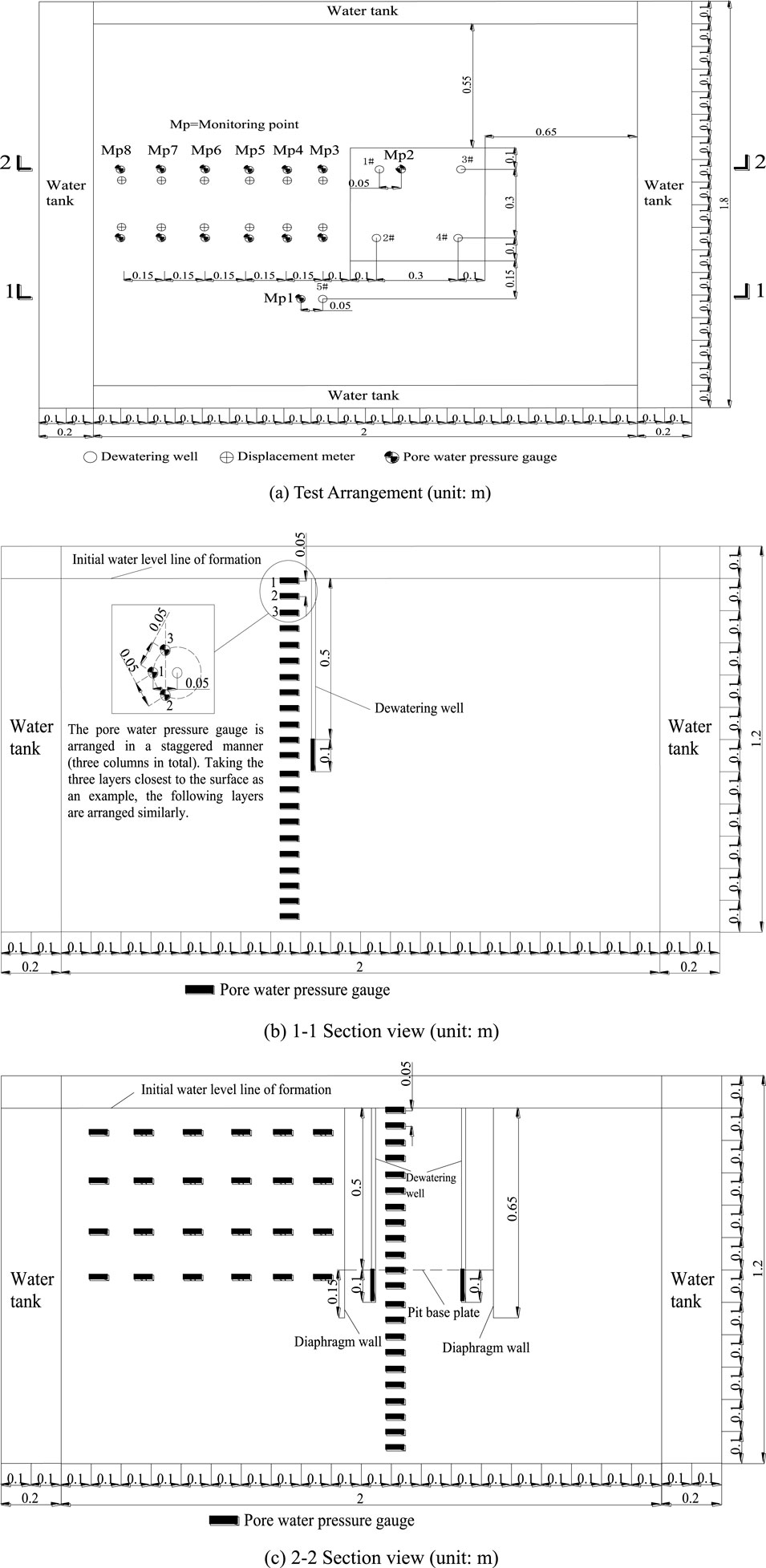
Figure 1. Test arrangement and section view. (A) Test Arrangement (unit: m). (B) 1-1 Section view (unit: m). (C) 2-2 Section view (unit: m).
The main body of the experimental model box measures 2 m in length, 1.8 m in width, and 1.2 m in height. There are replenishment tanks on all sides, which are separated from the main body by partitions with small holes. The thickness of the partition is 5 cm, and the opening area of the partition accounts for 48% of the total area. The maximum porosity of the test soil layer is 0.44. The number of openings in the partition can be adjusted to be consistent with the porosity of the soil layer, which meets the stable seepage water supply of the test soil layer and forms a constant head boundary condition. At the same time, a hollow cylindrical support is added to the water replenishment tank to ensure that the partition does not deform during the entire test process.
Per 10 cm formation material laid, the formation shall be tamped immediately. By injecting the water into the test tank from the water tank on high, the soil layer was made saturated from bottom to top. As certain settlement deformation may occur after saturation inside the soil layer, it is required to continue filling the soil to the required height. Only after 1–2 times of saturation and filling processes, the continued filling and installation of instruments and soil can be monitored, until filling to the height at 1.1 m as required by the test. Upon solidification of soil layer in the test tank, the water tanks and main tank around shall maintain the water level at 1.1 m high. As the formation solidifies under the weight force, when the reading change of displacement meter at the settlement observation point on the soil layer surface was less than 0.001 mm/d, it shows the soil layer solidification was basically finished. At the time, the model test had achieved the initial status prior to the construction, and meets the precipitation test condition.
In order to clearly display the location of the pore water pressure measuring points, the pore water pressure gauge in Figure 1 was filled in bold and arranged in a straight line. However, in the actual test process, the pore water pressure gauges were arranged in a staggered manner (three columns in total), with a thickness of 12.95 mm and an outer diameter of 13.18 mm, occupying a small space in the test area. Therefore, the impact on the seepage field, pore water pressure, and other factors is relatively small, and the influence of this factor can be ignored.
The test cases:
Case 1: fixed drawdown and dewatering test of partially penetrating single well outside the foundation pit in completely decomposed granites, and specified drawdown (0.1, 0.2, 0.3, 0.4, 0.5 m) dewatering test of 5# dewatering well in completely decomposed granites;
Case 2: fixed drawdown and dewatering test of partially penetrating single well in the foundation pit in completely decomposed granites, and specified drawdown (0.1, 0.2, 0.3, 0.4, 0.5 m) dewatering test of 1# dewatering well in completely decomposed granites;
Case 3: fixed drawdown and dewatering test of partially penetrating double wells in the foundation pit in completely weathered granite stratum, and specified drawdown (0.1, 0.2, 0.3, 0.4, 0.5 m) and dewatering test of 1# and 3# dewatering wells are carried out at the same time in completely decomposed granites.
3.2 Analysis of test results of effective influence depth measurement
The pore water pressure variation curves of 5#, 1#, and 1# and 3# precipitation wells in completely decomposed granites before and after stable precipitation at different depths are shown in Figure 2:
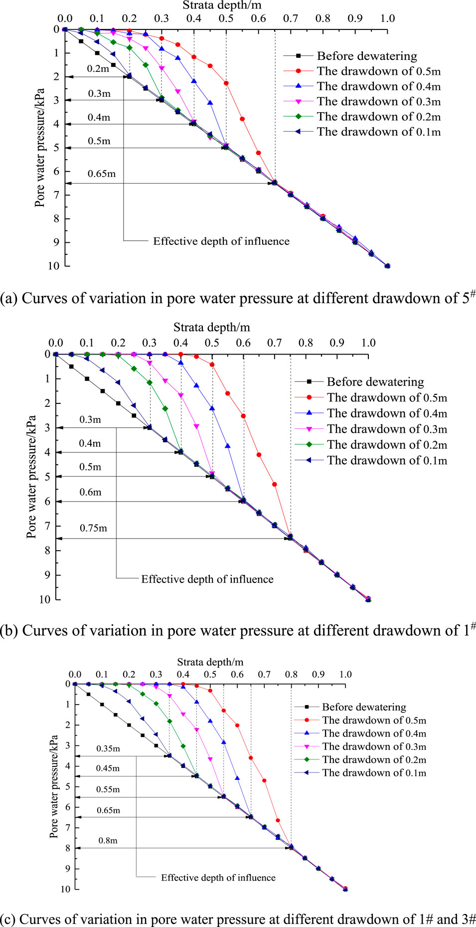
Figure 2. Curves of variation in pore water pressure at different drawdown. (A) Curves of variation in pore water pressure at different drawdown of 5#. (B) Curves of variation in pore water pressure at different drawdown of 1#. (C) Curves of variation in pore water pressure at different drawdown of 1# and 3#.
It can be seen from the comparison of the effective influence depths in Figure 2A, B that the effective influence depth of the dewatering of partially penetrating wells in the foundation pit is greater than that outside the foundation pit, which is due to the phenomenon of groundwater seepage around the bottom of the dewatering diaphragm wall in the foundation pit, which increases the effective influence depth of partially penetrating wells. The comparison of effective influence depth between Figure 2B, C shows that the effective influence depth of double well dewatering is slightly greater than that of single well dewatering, which is due to the influence of well group effect, which increases the water level drawdown in the foundation pit, and then increases the effective influence depth, but the increase is small.
It can be seen from the comparison of the effective influence depths in Figure 2A–C that The effective impact depth of incomplete well dewatering inside the foundation pit is greater than that outside the foundation pit. When other conditions are the same, the effective impact depth of incomplete well dewatering inside the foundation pit is 1.18 times that of outside the foundation pit on average. This is due to the phenomenon of groundwater seepage around the bottom of the dewatering diaphragm wall inside the foundation pit, which increases the effective impact depth of incomplete well dewatering; The effective impact depth of simultaneous dewatering of double wells in the foundation pit is greater than that of single well dewatering. The effective impact depth of simultaneous dewatering of double wells in the foundation pit is 1.12 times that of single well dewatering on average. This is due to the group well effect, which leads to an increase in seepage around the well, thereby increasing the impact on the effective impact depth.
3.3 Theoretical calculation of effective influence depth
Based on the water inflow calculation method of fully penetrating wells and partially penetrating wells in phreatic layer mentioned by Chen et al. (1999), the calculation formula of effective influence depth of partially penetrating wells is derived. As the permeability coefficient of typical phreatic strata gradually increases from top to bottom, and the bottom is strongly weathered granite stratum, the permeability coefficient is the largest, and there is no aquitard under the stratum, so the theoretical calculation can ignore the water release of aquitard itself.
The calculation formula of water inflow of fully penetrating single well is as follows:
Qf is the water inflow of fully penetrating single well in Phreatic strata, m3/d; k is the formation permeability coefficient, m/d; sw(f) is the drawdown of fully penetrating single well, m; R is the influence radius of dewatering well, m; rw is the radius of dewatering well, m; Ha is the thickness of the complete well aquifer, m.
The calculation formula of water inflow of partially penetrating single well is as follows:
Qp is the water inflow of partially penetrating single well in Phreatic strata, m3/d;k is the formation permeability coefficient, m/d; sw(p) is the drawdown of partially penetrating well, m; l is the filter length of dewatering well, m; R is the influence radius of dewatering well, m; rw is the radius of dewatering well, m.
The partially penetrating well can be equivalent to fully penetrating well with the same water inflow and drawdown:
According to Equations 1–3, the aquifer thickness Ha of the equivalent fully penetrating well can be approximately calculated by MATLAB software, that is, the effective influence depth of the partially penetrating well. The calculation results of the effective impact depth of partially penetrating well precipitation based on completely decomposed granite similar strata are shown in Table 2.
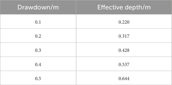
Table 2. Theoretical calculated results of effective depth.
The theoretical calculation results are compared with the test results, as shown in Table 3:
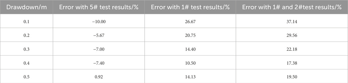
Table 3. Comparison of theoretical calculation results and test results in completely decomposed granite stratum.
From Table 3, it can be seen that the error between the theoretical calculation results and the test results of 5# dewatering wells outside the foundation pit is relatively small, and the error between the theoretical calculation results and the test results of 1# dewatering wells, 1# dewatering wells and 3# dewatering wells inside the foundation pit is relatively large, which are all smaller than the test results inside the foundation pit. The theoretical method is more suitable for the calculation of the effective influence depth of partially penetrating wells outside the foundation pit, and it needs to be multiplied by the amplification factor when applied in the foundation pit. When other conditions are the same, the effective influence depth of partially penetrating wells in the foundation pit is 1.18 times of that outside the foundation pit on average. The theoretical value of the effective influence depth of partially penetrating wells in the foundation pit can be obtained by multiplying the value calculated by the theoretical formula by the amplification factor of 1.18. The test result of double well simultaneous dewatering in the foundation pit is 1.12 times of the average of single well dewatering. The theoretical value of the effective influence depth of partially penetrating wells in the foundation pit can be obtained by multiplying the value calculated by the theoretical formula by the amplification factor of 1.18 in the foundation pit, and then multiplying the amplification factor of double well dewatering by 1.12.
4 Proposal and comparative verification of precipitation curve formula considering the influence of bypass infiltration
4.1 Analysis of experimental results
After sorting out and analyzing the pore water pressure monitoring data from measuring point 3 to monitoring point 8 in the 0.5 m drawdown test of 1# dewatering well in condition 2, the water level change curve of different buried depths outside the foundation pit after the dewatering is stable can be obtained, as shown in Figure 3A. Using the same experimental method, the water level variation curve of the gravelly cohesive soil layer was obtained, as shown in Figure 3B.
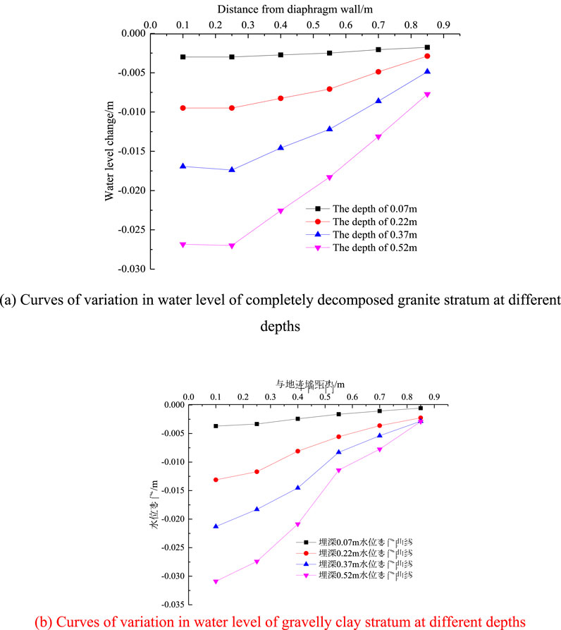
Figure 3. Curves of variation in water level at different depths. (A) Curves of variation in water level of completely decomposed granite stratum at different depths. (B) Curves of variation in water level of gravelly clay stratum at different depths.
As can be seen from Figure 3, within the depth range of the diaphragm wall after stable precipitation, the change of water level in the soil layer outside the foundation pit increases with the increase of the buried depth, decreases with the increase of the distance from the diaphragm wall, and increases with the increase of the permeability coefficient of the stratum. The precipitation curve form outside the foundation pit is quite different from the Dupuit precipitation curve. In the area near the diaphragm wall, the seepage around the bottom of the diaphragm wall occurs, and the groundwater seepage occurs in both horizontal and vertical directions, resulting in a great difference from the Dupuit precipitation curve form considering only the horizontal seepage.
4.2 Theoretical calculation method
According to Figure 3, Using MATLAB data fitting function, the front section of the precipitation curve outside the foundation pit is concave downward, and the rear section is convex upward. The fitting function is determined as follows:
y1 is the water content thickness of the soil layer at x outside the diaphragm wall, x is the distance from the diaphragm wall, C1, C2, d and e are the parameters in the function.
By substituting the relevant test data in Figure 3 into Equation 4, the parameter values of the fitting function can be obtained as shown in Table 4, where R is the correlation coefficient.
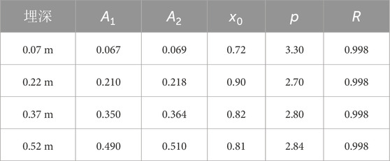
Table 4. Fitting values of parameters of completely decomposed granite stratum.
The physical quantities that affect the precipitation curve are the soil moisture thickness hw (hw=moisture thickness H-soil water level drawdown sw) closest to the diaphragm wall outside the foundation pit after stable precipitation, the soil moisture thickness H before precipitation, the soil permeability coefficient k and the effective influence depth Ha of partially penetrating wells in the foundation pit. The values of each physical quantity are shown in Table 5.
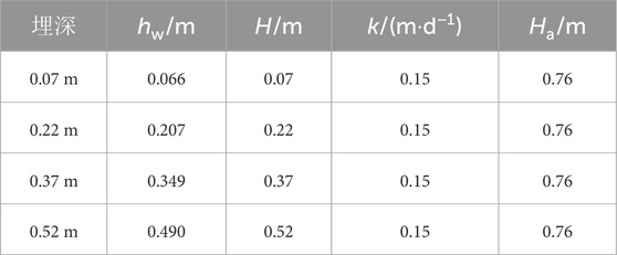
Table 5. Main physical values of completely decomposed granite stratum.
By comparing the data in Tables 4, 5, it can be seen that the values of parameter C1 and hw are equal, and the values of parameter A2 and H are basically equal. Parameter C1 can be replaced by hw, and parameter C2 can be replaced by H. The mean value of parameter d is basically the same as the value of the formula
Replace the parameters of the fitting function with the relevant physical quantities, and publicity (5) can be rewritten as:
The fitted precipitation curve calculated by the formula is compared with the precipitation curve of the model test, as shown in Figure 4:
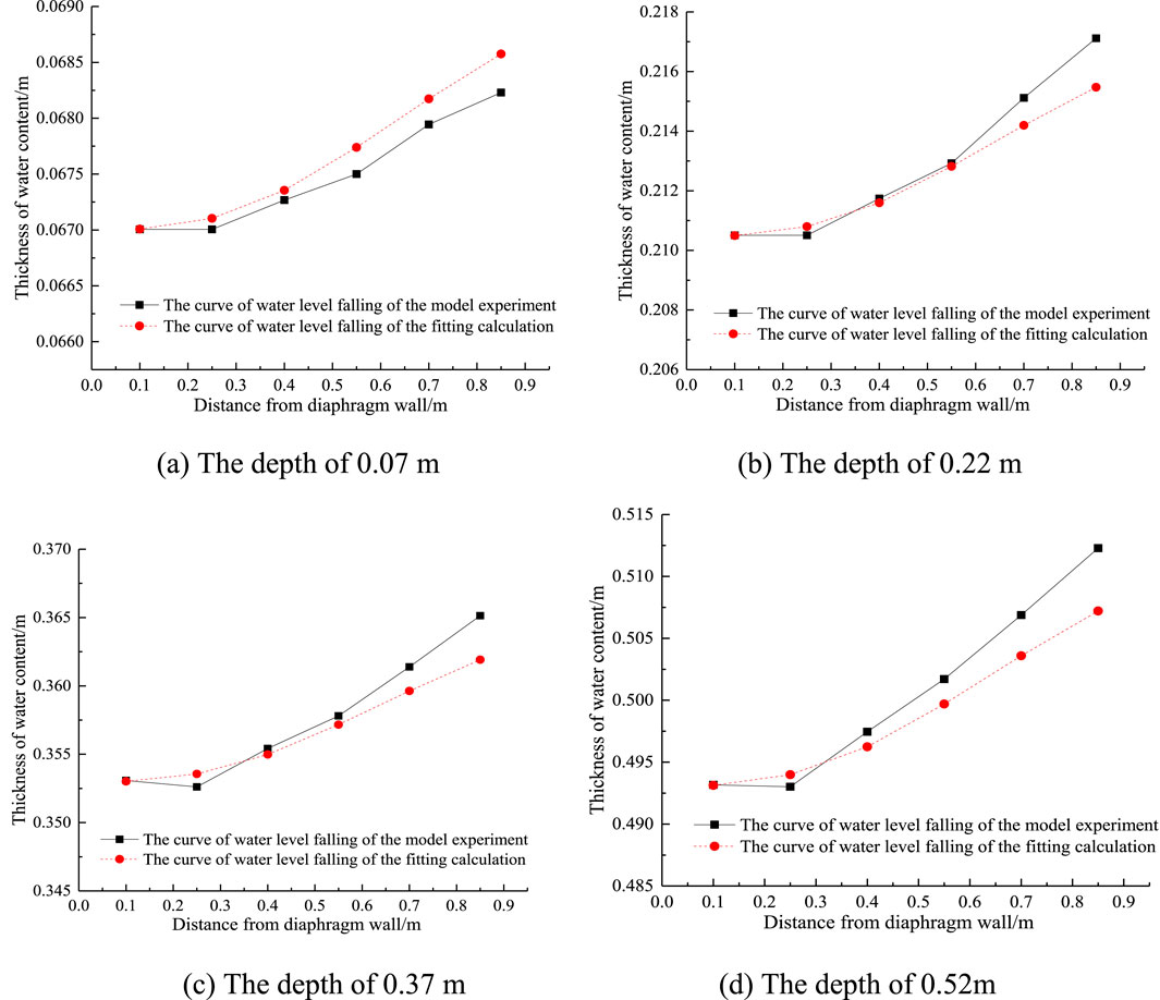
Figure 4. Comparison of curves of water level falling of completely decomposed granite stratum at different depths. (A) The depth of 0.07 m. (B) The depth of 0.22 m. (C) The depth of 0.37 m. (D) The depth of 0.52 m.
It can be seen from Figure 4 that the fitted precipitation curve is basically consistent with the test precipitation curve, indicating that Equation 5 can more accurately describe the precipitation trend outside the diaphragm wall.
4.3 Division of by-pass seepage zone
The precipitation curves considering the influence of seepage around are in the form of “first concave and then convex”. The concave part of the curve is the main influence area of seepage around. The characteristics of water flow are that there are horizontal and vertical seepage at the same time. The convex part of the curve is a non bypass seepage area, and the flow characteristics are mainly horizontal seepage, while the vertical seepage can be ignored. The inflection point of the curve from concave to convex is the boundary between the infiltration area and non infiltration area. It can be seen that the infiltration area and non infiltration area can be divided by finding the inflection point. As shown in Figure 5.
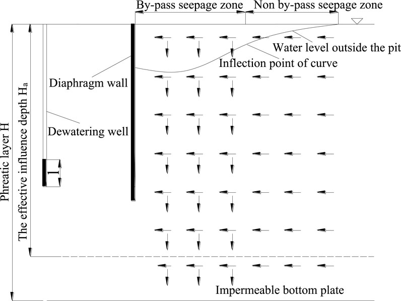
Figure 5. Calculation model of by-pass seepage zone partition.
Calculate the second derivative of the precipitation curve fitting formula and make the second derivative zero. The obtained x value is the distance between the inflection point of the precipitation curve and the diaphragm wall. The solution process is as follows:
Find the first derivative of h:
Find the second derivative of h:
According to Equation 8, the comparison between the inflection point position of precipitation curve obtained by theoretical calculation and the inflection point range of test precipitation curve is shown in Figures 6, 7.
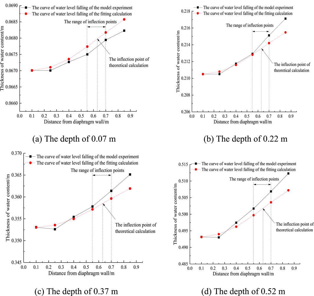
Figure 6. Inflection point location of curve of water level falling in completely decomposed granite stratum. (A) The depth of 0.07 m (B) The depth of 0.22 m. (C) The depth of 0.37 m (D) The depth of 0.52 m.
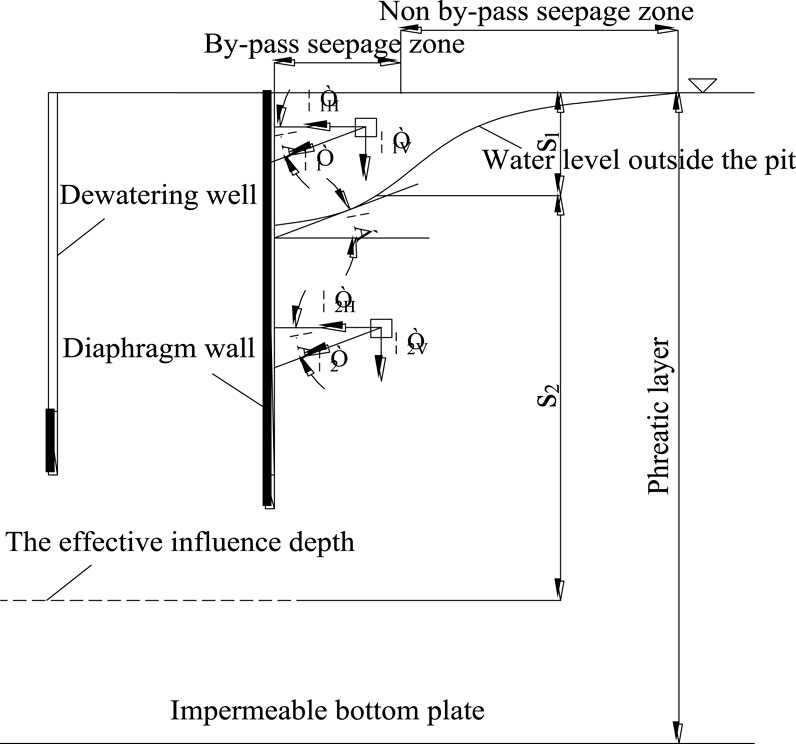
Figure 7. Simplified model of soil deformation calculation considered seepage force.
It can be seen from Figure 6 that the inflection points of precipitation curves calculated by the theory of different strata are within the range of test inflection points, indicating that the theoretical method can accurately divide the surrounding seepage area and non surrounding seepage area outside the pit, which has guiding significance for the construction and monitoring of foundation pit.
5 Modification of calculation method for surface settlement outside pit caused by precipitation
5.1 Correction calculation process of soil settlement outside the pit
The movement of groundwater caused by precipitation will generate a completely new seepage field and break the initial static equilibrium state, causing changes in both the seepage field and stress field of the soil around the well. The additional stress caused by seepage force is the main cause of soil consolidation and compaction due to water loss. Ignoring other secondary factors, the direction of this additional stress is approximately the same as the direction of seepage force. Due to the horizontal and vertical components of the seepage force in the seepage zone in Section 4.3, the direction of the seepage force is tangent to the stable groundwater surface at any point and points towards the foundation pit.
Based on the research ideas of Wu and Zhu (2016), after the formation of the precipitation infiltration curve, it is divided into a sparse part and a saturated part above and below the curve. Throughout the entire precipitation process, the soil in zone s1 was drained, while the soil in zone s2 remained saturated due to being below the stable groundwater level before and after precipitation. This article calculates the settlement of two separate parts of soil separately, taking into account the horizontal component of seepage force in the drained and saturated parts within the seepage zone.
The horizontal component of seepage force is considered in the drained part and saturated part within the surrounding seepage area, as shown in Figure 7.
Suppose the abscissa of any S point on the surface is x (the distance from the S point to the diaphragm wall), and calculate the tangent slope of the curve according to Equation 6:
According to the triangular geometry:
The vertical component of the additional stress caused by precipitation in the infiltration area s1 is as follows:
The vertical component of the additional stress caused by precipitation in the infiltration area s2 is as follows:
The settlement of dewatering area S1 is as follows:
The settlement of saturated zone S2 is as follows:
The final settlement of the surface outside the pit is as follows:
For the calculation of surface settlement in non permeable areas, the presence of horizontal components in the drained and saturated parts is not considered, and the additional stress caused by precipitation does not need to be multiplied by sinα.
5.2 Comparison of calculation results
According to Equations 7–14. The surface settlement changes of foundation pit obtained by simplified calculation method and modified calculation method in different strata are compared with the test results, as shown in Figure 8.
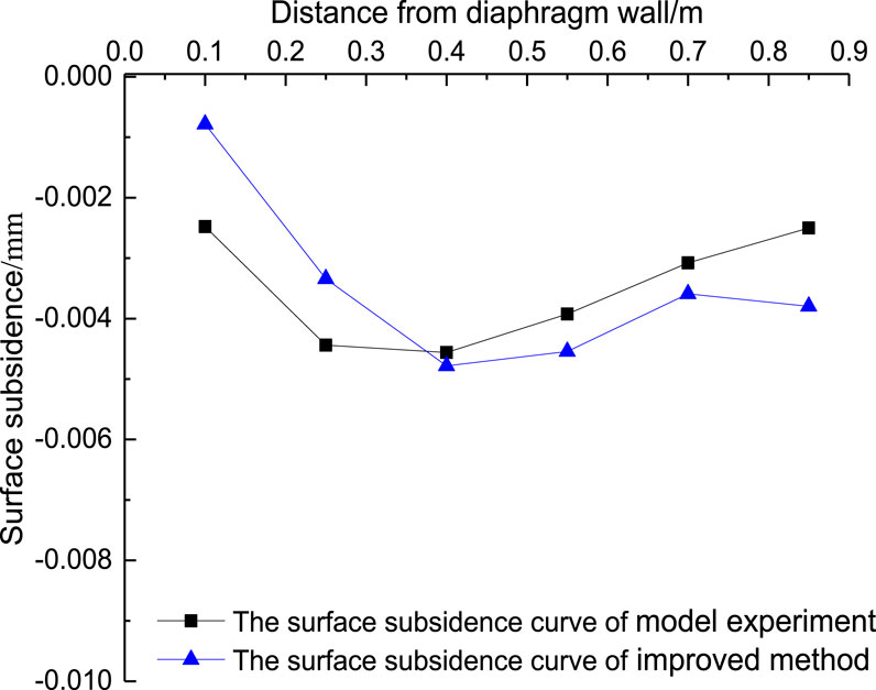
Figure 8. Comparison of surface subsidence curves of completely decomposed granite stratum.
It can be seen from Figure 8 that the surface settlement curve outside the pit obtained by considering the effect of seepage force in the surrounding seepage area is more consistent with the surface settlement monitoring curve in the model test, and this calculation method can be estimated accurately and quickly.
6 Study on the law of surface deformation outside the pit caused by dewatering in the foundation pit
The layout of the model test on the deformation law of the surface outside the pit caused by the dewatering of partially penetrating wells in the foundation pit is shown in Figure 9. Yang et al. (2023) provided the testing method and steps for the foundation pit dewatering model.
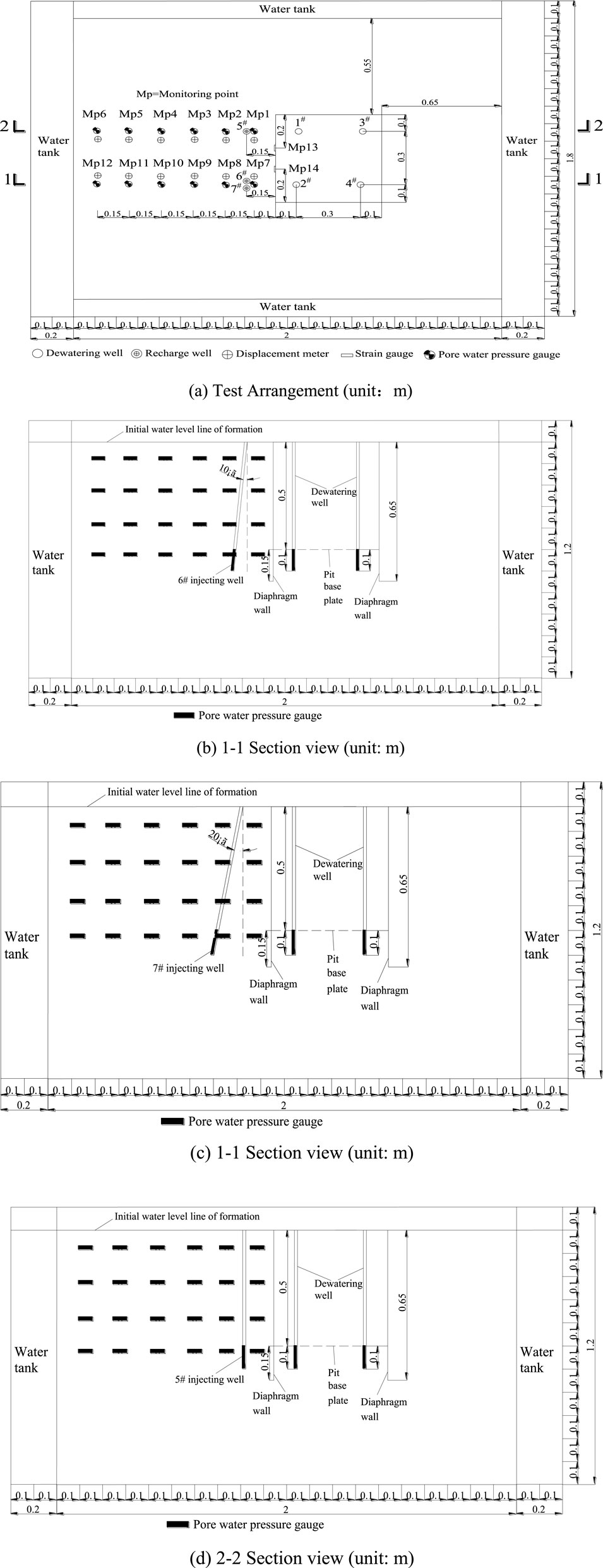
Figure 9. Test arrangement and section view. (A) Test Arrangement (unit:m). (B) 1-1 Section view (unit: m). (C) 1-1 Section view (unit: m). (D) 2-2 Section view (unit: m).
The test cases are as follows:
Case 1: large drawdown (0.5 m) of a single well in the foundation pit
Case 2: large drawdown (0.5 m) of double wells in the foundation pit
Case 3: large depth (0.5 m) dewatering inside the foundation pit, and 1/2 well deep recharge outside the foundation pit;
Case 4: large depth (0.5 m) dewatering in the foundation pit, and full well deep recharge outside the foundation pit;
Case 5: large depth (0.5 m) dewatering inside the foundation pit, and 10° inclined recharge between the outside of the foundation pit and the vertical direction;
Case 6: large depth (0.5 m) dewatering inside the foundation pit, and 20° inclined recharge between the outside of the foundation pit and the vertical direction.
6.1 Deformation law of surface outside the pit caused by dewatering in the foundation pit
The time history curve of surface settlement at different distances from the diaphragm wall outside the foundation pit is shown in cases 1 and 2, as shown in Figure 10.
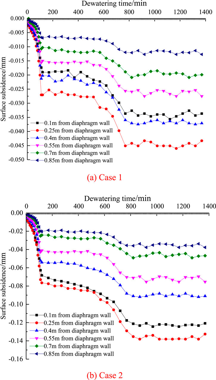
Figure 10. The time history curves of surface subsidence. (A) Case 1. (B) Case 2.
It can be seen from Figure 10A that the first 120 min after the beginning of precipitation is in the period of sudden decline of land subsidence, and the subsidence rate is the highest. 770 min after the beginning of precipitation, all points of land subsidence gradually enter the period of settlement stability. The main settlement is concentrated within 0.55 m from the diaphragm wall, that is, the main settlement is concentrated within the by-pass seepage area.
It can be seen from Figure 10B that the first 120 min after the beginning of precipitation is in the period of sudden decline of land subsidence, and the subsidence rate is the highest. 870 min after the beginning of precipitation, all points of land subsidence gradually enter the period of settlement stability. The main settlement is concentrated within 0.7 m from the diaphragm wall, that is, the main settlement is concentrated within the by-pass seepage area.
The variation value of surface settlement outside the foundation pit caused by double well dewatering is 2–3 times greater than that caused by single well dewatering. It can be seen that double well dewatering will produce the superposition effect of surface settlement. Therefore, the influence of superposition effect should be considered in multi well dewatering.
6.2 Law of surface settlement outside the pit caused by dewatering inside the pit and recharging outside the pit
The time history curve of surface settlement outside the foundation pit at different distances from the diaphragm wall is in case 3–6, as shown in Figure 11.
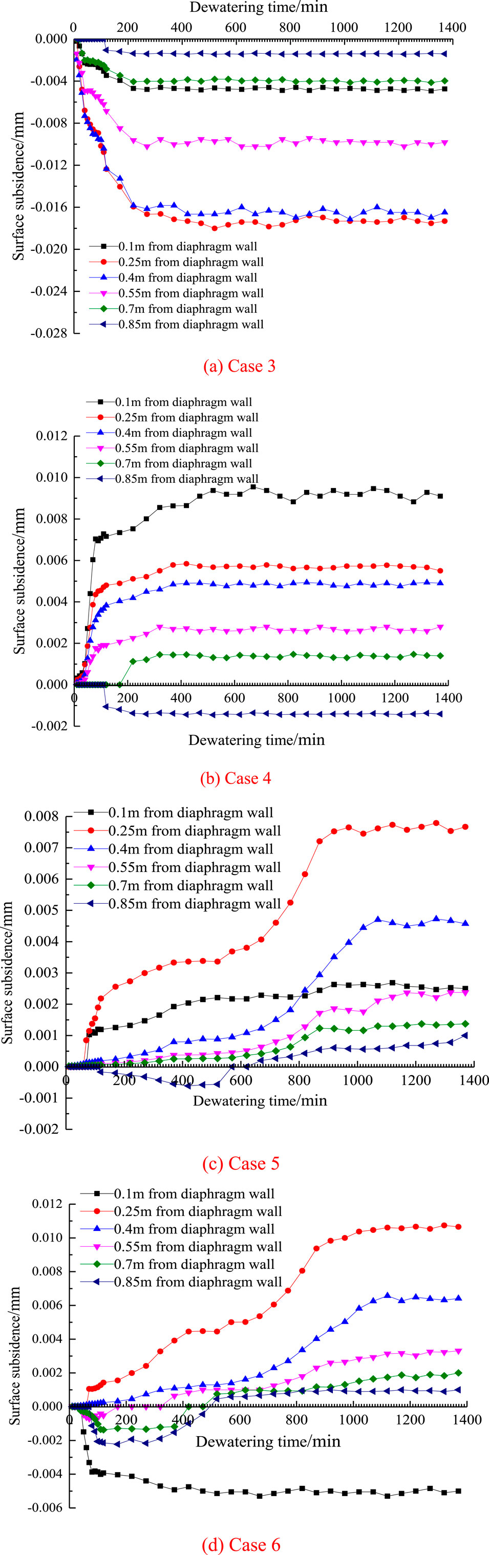
Figure 11. The time history curves of surface subsidence. (A) Case 3. (B) Case 4. (C) Case 5. (D) Case 6.
As can be seen from Figure 11A, when half well deep reinjection is carried out outside the foundation pit, the surface settlement of the reinjection well is negative at the side near the diaphragm wall, indicating that the surface is sinking downward. When the precipitation reinjection is stable, the maximum value is −0.005 mm. When the reinjection well is far away from the diaphragm wall, the surface settlement values are negative, indicating that the surface is sinking downward, and when the precipitation reinjection is stable, the maximum value is −0.017 mm.
It can be seen from Figure 11B that when the whole well deep reinjection is carried out outside the foundation pit, the surface settlement is positive at the side of the reinjection well adjacent to the diaphragm wall, indicating that the surface is uplifted upward. When the precipitation reinjection is stable, the maximum value is 0.009 mm. When the reinjection well is far away from the diaphragm wall, the surface settlement is positive, indicating that the surface is uplifted upward, and when the precipitation reinjection is stable, the maximum value is 0.005 mm. It can be seen that the whole well deep reinjection is more than the half deep reinjection, and the surface settlement of the reinjection well near the diaphragm wall has decreased by 0.014 m and far away from the diaphragm wall has decreased by 0.022 m.
As can be seen from Figure 11C, when the whole well deep reinjection with an angle of 10° from the vertical direction is carried out outside the foundation pit, the surface settlement value is positive at the side of the reinjection well adjacent to the diaphragm wall, indicating that the surface is uplifted upward. When the precipitation reinjection is stable, the maximum value is 0.002 mm. When the reinjection well is far away from the diaphragm wall, the surface settlement values are positive, indicating that the surface is uplifted upward, and when the precipitation reinjection is stable, the maximum value is 0.008 mm. It can be seen that the inclined 10° full well deep reinjection is better than the vertical full well deep reinjection, and the surface settlement at the side of the reinjection well adjacent to the diaphragm wall has decreased by 0.007 m, while the surface settlement at the side away from the diaphragm wall has decreased by 0.025 m.
It can be seen from Figure 11D, when the whole well deep reinjection with an angle of 20° with the vertical direction is carried out outside the foundation pit, the surface settlement change value is negative at the side of the reinjection well adjacent to the diaphragm wall, indicating that the surface is sinking downward. When the precipitation reinjection is stable, the maximum value is −0.005 mm, and the reinjection well is far away from the side of the diaphragm wall, the surface settlement values are positive, indicating that the surface is uplifted upward, and when the precipitation reinjection is stable, the maximum change value is 0.011 mm. It can be seen that the inclined 20° full well deep reinjection is better than the inclined 10° full well deep reinjection, and the surface settlement at the side of the reinjection well adjacent to the diaphragm wall has decreased by 0 m, while the surface settlement at the side away from the diaphragm wall has decreased by 0.028 m.
6.3 Deformation law of the diaphragm wall caused by dewatering in foundation pit
The variation curve of diaphragm wall lateral displacement with buried depth under different precipitation time conditions is in case 1 and case 2, as shown in Figure 12.
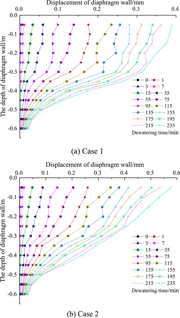
Figure 12. The curves of lateral displacement of diaphragm wall with different depth under different precipitation time cases. (A) Case 1. (B) Case 2.
It can be seen from Figure 12 that the lateral displacement of the diaphragm wall increases gradually with the increase of precipitation time for both single well and double well dewatering. The maximum lateral displacement of the diaphragm wall with a single well dewatering depth of 0.5 m is 0.39 mm, which is 0.078% of the precipitation depth. The maximum lateral displacement of the diaphragm wall with a double well dewatering depth of 0.5 m is 0.58 mm, which is 0.12% of the precipitation depth.
6.4 Deformation law of diaphragm wall caused by dewatering inside foundation pit and recharging outside foundation pit
The variation curve of diaphragm wall lateral displacement with buried depth under different precipitation time conditions is in case 3–6, as shown in Figure 13.
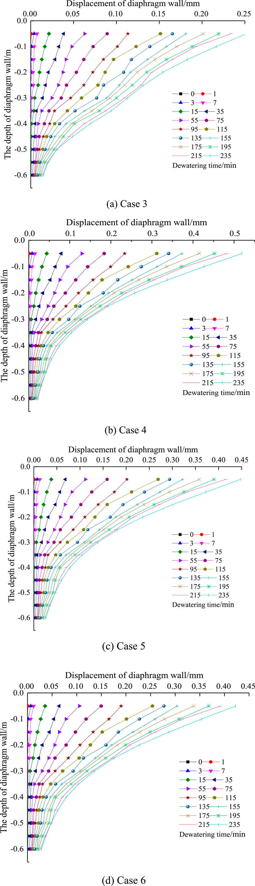
Figure 13. The curves of lateral displacement of diaphragm wall with different depth under different precipitation time cases. (A) Case 3. (B) Case 4. (C) Case 5. (D) Case 6.
It can be seen from Figure 13A that with the increase of precipitation recharge time, the displacement value of diaphragm wall to the inner side of foundation pit gradually increases. The maximum lateral displacement of diaphragm wall is 0.25 mm, which is 0.05% of the precipitation depth. The lateral displacement value of diaphragm wall decreases by 34% compared with that without recharge. This is because within the range of reinjection depth, the displacement of replenished soil particles to the diaphragm wall decreases with the reinjection depth being 1/2 of the well depth, and the reinjection seepage force towards the diaphragm wall is small, which causes the diaphragm wall to move to the inside of the pit much less than the reduced displacement of soil particles to the diaphragm wall, resulting in that when the reinjection depth is 1/2 of the well depth, the lateral displacement of the diaphragm wall is less than that without reinjection.
It can be seen from Figure 13B that with the increase of precipitation reinjection time, the displacement value of diaphragm wall to the inner side of foundation pit gradually increases, and the maximum lateral displacement of diaphragm wall is 0.51 mm, which is 0.1% of the precipitation depth. The lateral displacement value of diaphragm wall increases by 24% compared with that without reinjection. This is because within the range of reinjection depth, the displacement of replenished soil particles to the diaphragm wall decreases with the reinjection depth being the full well depth, and the reinjection seepage force towards the diaphragm wall is large, causing the diaphragm wall to move to the inside of the pit more than the reduced displacement of soil particles to the diaphragm wall, resulting in the lateral displacement of the diaphragm wall greater than that without reinjection when the reinjection depth is the full well depth.
It can be seen from Figure 13C that with the increase of precipitation reinjection time, the displacement value of diaphragm wall to the inner side of foundation pit gradually increases. The maximum lateral displacement of diaphragm wall is 0.45 mm, which is 0.09% of the precipitation depth. The lateral displacement value of diaphragm wall increases by 13% compared with that without reinjection. The lateral displacement of the diaphragm wall of the inclined 10° full depth reinjection is significantly reduced compared with the vertical full depth reinjection.
It can be seen from Figure 13D that with the increase of precipitation recharge time, the displacement value of the diaphragm wall to the inner side of the foundation pit gradually increases. The maximum lateral displacement of the diaphragm wall is 0.41 mm, which is 0.082% of the precipitation depth. The lateral displacement value of the diaphragm wall increases by 4.9% compared with that without recharge. The lateral displacement value of the diaphragm wall of the inclined 20° full well deep reinjection is less than that of the inclined 10° full well deep reinjection.
7 Conclusion
(1) Through the experimental analysis of the mechanism of groundwater seepage around the foundation pit, the effective influence depth of precipitation in the foundation pit is greater than that outside the foundation pit, and the effective influence depth of double well precipitation is greater than that of single well precipitation. It reveals that the precipitation curve outside the foundation pit under the influence of seepage around the foundation pit presents the characteristics of “first concave and then convex”, and puts forward the calculation formula of surface settlement change outside the pit caused by partially penetrating well precipitation in the completely decomposed granite stratum. The calculation results of the theoretical formula are in good agreement with the experimental results, which has good accuracy and applicability.
(2) The surface settlement outside the pit caused by dewatering in the foundation pit is mainly concentrated in the surrounding seepage area, and the change value of surface settlement outside the pit caused by double well dewatering is 2–3 times greater than that caused by single well dewatering. When the whole well is vertically reinjected, the maximum surface settlement is 0.009 mm at the side near the diaphragm wall, and 0.005 mm at the side far away from the diaphragm wall. When the whole well is at an inclination of 10°, the maximum surface settlement is 0.002 mm at the side near the diaphragm wall, and 0.008 mm at the side far away from the diaphragm wall. When the whole well is at an inclination of 20°, the maximum surface settlement is −0.005 mm at the side near the diaphragm wall, and 0.011 mm at the side far away from the diaphragm wall. The full well depth recharge with an inclination of 20° has the largest influence on the surface settlement of the foundation pit, and the recharge effect is the best.
(3) The lateral displacement of diaphragm wall increases by 24% compared with that without reinjection. The maximum lateral displacement of the diaphragm wall is 0.09% of the precipitation depth when the whole well is tilted at 10° for reinjection, and the lateral displacement of the diaphragm wall increases by 13% compared with that without reinjection. The maximum lateral displacement of the diaphragm wall is 0.082% of the precipitation depth when the whole well is tilted at 20° for reinjection, and the lateral displacement of the diaphragm wall increases by 4.9% compared with that without reinjection. The full well depth recharge with an inclination of 20° has the least impact on the diaphragm wall, and the recharge effect is the best.
Data availability statement
The original contributions presented in the study are included in the article/supplementary material, further inquiries can be directed to the corresponding author.
Author contributions
QY: Conceptualization, Formal Analysis, Investigation, Supervision, Visualization, Writing–original draft. SC: Data curation, Methodology, Writing–review and editing.
Funding
The author(s) declare that financial support was received for the research, authorship, and/or publication of this article. This study is supported by the National Science Fund (52272341) and Guangzhou Panyu Polytechnic project (2023KJ21) and National Natural Science Foundation Youth Program (41902298) and Guangdong Ordinary University Characteristic Innovation Project (2024KTSCX320) and Guangzhou Science and Technology Bureau Basic and Applied Basic Research Project (202201011855) and the Open Project Program of Hebei Center for Ecological and Environmental Geology Research (JSYF-202304) and the Guangdong Provincial Department of Education Innovation Team Project (2023KCXTD071).
Conflict of interest
The authors declare that the research was conducted in the absence of any commercial or financial relationships that could be construed as a potential conflict of interest.
Generative AI statement
The author(s) declare that no Generative AI was used in the creation of this manuscript.
Publisher’s note
All claims expressed in this article are solely those of the authors and do not necessarily represent those of their affiliated organizations, or those of the publisher, the editors and the reviewers. Any product that may be evaluated in this article, or claim that may be made by its manufacturer, is not guaranteed or endorsed by the publisher.
References
Chen, Y. C., Li, J. P., Di, G. E., and Liao, Z. J. (2008). Analysis and repair measures for influence of dewatering of deep foundation pits on surrounding environment. Chin. J. Geotechnical Eng. 30 (10), 319–322.
Chen, C. X., and Lin, M. (1999). Groundwater Dynamics. Editor M. Chin China University of Geosciences Press.
Debasis, R., and Keith, E. R. (2009). Surface settlements at a soft soil site due to bedrock dewatering. Eng. Geol. 107, 109–117. doi:10.1016/j.enggeo.2009.05.006
Gong, X. N., and Zhang, J. (2011). Settlement of overlaying soil caused by decompression of confined water. Chin. J. Geotechnical Eng. 33 (1), 145–149. doi:10.1016/j.cnsns.2011.02.018
Huang, Y. H., and Lu, Y. J. (2009). A method for estimating land extraction and subsidence induced by groundwater its application to site evaluation of Yizhuang light railway in Beijing. Rock Soil Mech. 8 (30), 2457–2462. doi:10.16285/j.rsm.2009.08.052
Jia, Y. J., Liang, F. Y., and Cui, Z. D. (2016). Analysis of soil deformation caused by decompression of confined water based on displacement coordination condition. Rock Soil Mech. 37 (z1), 48. doi:10.16285/j.rsm.2016.S1.005
Li, L., Zhang, J. G., and Yang, M. (2008). Simplified analysis of settlement due to dewatering of foundation pits. Chin. J. Geotechnical Eng. 30 (1), 306–309.
Liu, F. M. (2016). Research on ground settlement caused by dewatering considering the initial hydraulic gradient and interlayer recharge. Beijing: China Academy of Building Research.
Liu, J., Chen, J. J., and Wang, J. H. (2013). Fluid-solid coupling analysis of multi-grade dewatering in Hongqiao transport hub. Chin. J. Geotechnical Eng. 35 (zk1), 210–215.
Liu, J. L. (2002). Research on the simplified method of design for dewatering by annular partially penetrated wells in phreatic aquifer. Geotech. Eng. Tech. (5), 29–301.
Luo, G. Y., Pan, H., and Cao, H. (2004). Analysis of settlements caused by decompression of confined water. Rock Soil Mech. (s2), 196–200. doi:10.16285/j.rsm.2004.s2.040
Lv, B. Q., Feng, X. L., and Xiong, Z. H. (2020). Theory of artesian well flow in ancient river in Wuhan and its application in foundation pit dewatering. Chin. J. Geotechnical Eng. 42 (3), 533–541. doi:10.11779/CJGE202003015
Ran, L., and Hu, Q. (2009). Analysis of seepage failure of deep foundation pit in silty sand. Rock Soil Mech. 30 (1), 241–246. doi:10.1016/S1874-8651(10)60073-7
Shi, J., Wu, B., Liu, Y., Xu, S., Hou, J., Wang, Y., et al. (2022). Analysis of the influence of groundwater seepage on the deformation of deep foundation pit with suspended impervious curtain. Adv. Mech. Eng. 14 (3), 16878132221085128. doi:10.1177/16878132221085128
Wang, C. B., Ding, W. Q., and Liu, W. J. (2013). Distribution law of soil settlement caused by unsteady dewatering of confined water. J. Tongji Univ. Nat. Sci. 41 (3), 361–367. doi:10.3969/j.issn.0253-374x.2013.03.008
Wang, J. H., Tao, L. J., and Han, X. (2015). Effect of suspended curtain depth into stratum on discharge rate and its optimum design. J. Beijing Univ. Technol. 9 (41), 1390–1398. doi:10.11936/bjutxb2015010006
Wang, J. X., Wu, L. G., and Zhu, Y. F. (2009). Mechanism of dewatering-induced ground subsidence in deep subway station pit and calculation method. Chin. J. Rock Mech. Eng. 28 (5), 1010–1019. doi:10.1109/CLEOE-EQEC.2009.5194697
Wu, J. D., Ding, W. Q., and Liu, W. J. (2012). Influence of seepage flows on embedded depth of multi-pivot diaphragm walls. Chin. J. Geotechnical Eng. 34 (s1), 54–59.
Wu, J. Y., Jing, H., Gao, Y., Meng, Q., Yin, Q., and Du, Y. (2022). Effects of carbon nanotube dosage and aggregate size distribution on mechanical property and microstructure of cemented rockfill. Cem. Concr. Compos. 127, 104408. doi:10.1016/j.cemconcomp.2022.104408
Wu, J. Y., Wong, H. S., Zhang, H., Yin, Q., Jing, H., and Ma, D. (2024). Improvement of cemented rockfill by premixing low-alkalinity activator and fly ash for recycling gangue and partially replacing cement. Cem. Concr. Compos. 145, 105345. doi:10.1016/j.cemconcomp.2023.105345
Wu, Y. Q., and Zhu, Y. P. (2016). Calculation of settlement considering unsaturated soil influence of the dewatering of foundation pits. Eng. Mech. 33 (3), 179–187. doi:10.6052/j.issn.1000-4750.2014.12.1022
Xu, C. J., Zeng, Y. T., Tian, W., and Chen, M. (2021). Analytical analysis of influence of dewatering on adjacent pipelines based on Pasternak foundation. J. Shanghai Jiaot. Univ. 55 (6), 652. doi:10.16183/j.cnki.jsjtu.2020.007
Xu, X. B., Hu, Q., Huang, T. M., Chen, Y., Shen, W. M., and Hu, M. Y. (2022). Seepage failure of a foundation pit with confined aquifer layers and its reconstruction. Eng. Fail. Anal. 138, 106366. doi:10.1016/J.ENGFAILANAL.2022.106366
Yang, Q. Y., Chen, S., and Yuan, Y. (2023). Experimental study on the variation rule of water level outside the pit caused by dewatering in the pit and the rule of reinjection outside the pit. Front. Mater. 10, 1192557. doi:10.3389/fmats.2023.1192557
Yuan, H., Zhang, Q. H., and Zhang, j. W. (2013). Estimation method for surface subsidence induced by dewatering under the constraint of lateral friction. J. Shanghai Jiaot. Univ. 47 (8), 1329–1334. doi:10.16183/j.cnki.jsjtu.2013.08.028
Zhang, B. F. (2014) Study on the characteristics of groundwater seepage field in engineering. Research. Beijing: China Academy foundation pit of Building.
Zhang, Z. H., Qin, W. L., Zhang, Q. X., and Guo, Y. C. (2021). Water control optimization method of foundation pit with suspended waterproof curtain. J. Northeast. Univ. Nat. Sci. 42 (2), 242. doi:10.12068/j.issn.1005-3026.2021.02.014
Zhang, Z. M., Zhao, Y. B., and Wu, S. M. (2010). Design and analysis of retaining system of foundation pit of qingchun road river-crossing tunnel in hangzhou. Chin. J. Geotechnical Engineeing 32 (9), 1399–1405.
Keywords: foundation pit dewatering, model test, effective influencing depth, dewatering curve, deformation law, reinjection form
Citation: Yang Q and Chen S (2025) Research on the deformation mechanism and law caused by the influence of seepage on foundation pit dewatering. Front. Earth Sci. 12:1523165. doi: 10.3389/feart.2024.1523165
Received: 05 November 2024; Accepted: 26 December 2024;
Published: 22 January 2025.
Edited by:
Jiangyu Wu, China University of Mining and Technology, ChinaReviewed by:
Guangchang Yang, University of Science and Technology Beijing, ChinaYuan Gao, Nantong University, China
Copyright © 2025 Yang and Chen. This is an open-access article distributed under the terms of the Creative Commons Attribution License (CC BY). The use, distribution or reproduction in other forums is permitted, provided the original author(s) and the copyright owner(s) are credited and that the original publication in this journal is cited, in accordance with accepted academic practice. No use, distribution or reproduction is permitted which does not comply with these terms.
*Correspondence: Song Chen, Y2hlbm5zb25nZ0AxNjMuY29t