- 1Tianjin Municipal Engineering Design and Research Institute Co., Ltd., Tianjin, China
- 2Faculty of Engineering, China University of Geosciences, Wuhan, China
- 3National Center for International Research on Deep Earth Drilling and Resource Development, China University of Geosciences, Wuhan, China
The Hutou Beishan Mega Tunnel frequently experiences significant deformation and instability collapse when passing through weak and fractured rock strata, leading to frequent design modifications and adversely impacting the construction progress and costs. This paper employs the finite-discrete element method (FDEM) to investigate the mechanisms and characteristics of large deformations in soft rock and analyzes the effects of in-situ stress and lateral pressure coefficients on the stability of soft rock tunnels. The results indicate that: (1) Once the compressive stress concentration exceeds the shear strength of the surrounding rock, shear failure occurs, with the resulting cracks predominantly forming X-shaped conjugate fractures. The shape of the excavation damage zone (EDZ) corresponds to the stress state; (2) Under hydrostatic stress conditions, the extent of damage to weak surrounding rock is influenced by the in-situ stress. At lower in-situ stress levels, only a few cracks appear at the edges of the surrounding rock, and deformation is minimal. At higher in-situ stress levels, cracks extend deeper into the tunnel, crushing shallow rock; (3) The failure characteristics of the tunnel vary with different lateral pressure coefficients. As the lateral pressure coefficient changes, the shape of the EDZ also changes, and the concentrated damage zone shifts from the arch waist to the crown as the lateral pressure coefficient increases.
1 Introduction
During the construction of tunnels in western China, complex geological conditions present various challenges and unforeseen problems. In particular, under conditions of deep burial and high in-situ stress, soft rock tunnels often experience significant large deformations. In recent years, through the construction of projects such as the Muzhailing Tunnel (Sun et al., 2021), Xianglushan Tunnel (Ma et al., 2019), Maoxian Tunnel (Chen et al., 2019), and Wuduxi Tunnel (Wu et al., 2022), scholars have accumulated considerable experience and made significant progress in the study of large deformations in soft rock tunnels. For example, Zhao et al. (2023) analyzed the mechanical response during tunnel construction in weak surrounding rock through field monitoring of the Qichong Village No.1 Tunnel and proposed technical suggestions for large-section tunnels. Ding et al. (2017) studied the stability of large-diameter parallel diversion tunnels in soft rock through field monitoring and testing, suggesting improved designs and reinforcement measures. Zhu et al. (2022) investigated the deformation and damage mechanisms of soft rock roadways based on field surveys and proposed a support system focused on reinforcing weak structural parts. Wu et al. (2022) proposed a “double-layer primary support-secondary lining” construction method to control large deformations in weak surrounding rock, and field tests validated the feasibility of this double-layer support.
However, field monitoring of the mechanical response of soft rock tunnels after excavation requires long-term observation, which is costly. Moreover, the data collected are limited by equipment layout and monitoring points, making it difficult to fully capture crack evolution and stress state in the surrounding rock. Laboratory experiments, while useful, struggle to reflect the true mechanical behavior of large-scale surrounding rock during excavation, and replacing experimental models is both costly and time-consuming. In contrast, numerical simulation methods, with advantages such as shorter time requirements, lower costs, and high reproducibility, have proven to be highly efficient in addressing complex nonlinear problems. As a result, these methods are increasingly employed in the study of large deformation in soft rock tunnels (Wu et al., 2021; Fu et al., 2024). For instance, Li et al. (2014) developed a degradation constitutive model based on FLAC3D to capture the displacement of weak rocks surrounding tunnels. Tang et al. (2022) used GDEM software to explore the effectiveness of combined support methods for high in-situ stress soft rock tunnels. Zhan et al. (2020) conducted numerical simulations and theoretical analyses to investigate the instability mechanisms of soft rock roadways under multi-factor coupling. Akgün et al. (2014) analyzed the stress distribution and deformation characteristics of the surrounding soft rock of the Geçilmez Tunnel using finite element methods and simulated the interaction between the support system and the rock mass. Wang Y. et al. (2023) highlighted the significant impact of creep in weak surrounding rock on the long-term stability of tunnels and verified the reliability of their model through numerical simulations and field data. However, these numerical methods have certain limitations in fully capturing the crack initiation, propagation, and coalescence process in weak surrounding rock tunnels.
In recent years, the finite-discrete element method (FDEM) has been increasingly applied to the simulation of large deformations in soft rock tunnels, with studies showing that this method can effectively capture the instability and failure processes of such tunnels (Wu et al., 2023; Wu et al., 2024). For example, Lisjak et al. (2015) used FDEM to analyze the deformation and failure process of soft rock surrounding tunnels, revealing the key role of bedding planes in the formation of the excavation damaged zone (EDZ). Deng et al. 2023) used FDEM simulations to study the large deformation mechanism, classification, and prediction of soft rock tunnels. Wang et al. (2022) employed a humidity diffusion-deformation-fracture coupling model in FDEM software MultiFracS to simulate the deformation and failure of soft rock roadways in high-humidity environments, providing reference data for the engineering control of humidity-related issues. Furthermore, many scholars have developed various coupling models based on FDEM, broadening its application in engineering (Yan and Zheng, 2016; Yan and Zheng, 2017a; Yan and Zheng, 2017b; Yan and Jiao, 2018; Yan et al., 2018; Yan et al., 2022; Hu et al., 2025). However, previous FDEM studies have either simplified the size and shape of tunnel models or lacked validation against real engineering cases, limiting the direct applicability of their findings to specific engineering practices.
Therefore, this study focuses on the Hutou Beishan Mega Tunnel, considering the geological conditions around the tunnel and the disaster phenomena that occurred during the excavation process. GPU-parallel FDEM software MultiFracS (Yan et al., 2022; Yan et al., 2023a; Yan et al., 2023b) was used for numerical simulations to reveal the failure mechanisms of soft rock surrounding the tunnel and analyze the effects of in-situ stress and lateral pressure coefficients on the stability of the soft rock tunnel. The aim is to provide valuable references for the design of support systems in subsequent tunnel construction.
2 Fundamental of FDEM
2.1 Basic equation
In the FDEM method, the continuum is discretized into a finite element mesh composed of triangular elements, with zero-thickness joint elements inserted between adjacent triangular elements, as shown in Figure 1. The initiation, propagation, and intersection of cracks are simulated through the fracture of the joint elements. This method combines the advantages of both the finite-element method (FEM) and the discrete-element method (DEM), making it suitable for handling complex crack evolution and material failure processes. The equation of motion for the nodes is as Equation 1 (Munjiza et al., 2004):
Where the M is the mass matrix, C is the damping matrix, x is the vector of nodal displacements, and F(x) is the unbalanced force vector of the node.
2.2 Constitutive model of joint elements
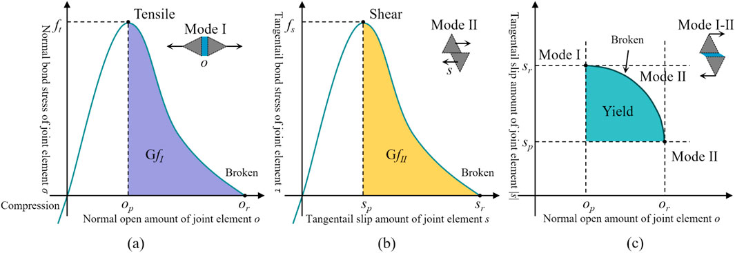
As shown in Figure 2, the constitutive model of the joint element classifies the damage modes into three categories: Mode I tensile failure, Mode II shear failure, and Mode III tensile-shear mixed failure. The damage state of the joint element can be determined based on its normal and tangential displacements. The damage variable D of the joint element is defined by Equation 2 (Munjiza et al., 2004):
Where o and s represent the normal and tangential displacements of the joint element, respectively. op and or are the critical normal displacement and the maximum normal displacement of the joint element under pure tensile conditions, while sp and sr are the critical tangential displacement and the maximum tangential displacement of the joint element under pure shear conditions. If the damage variable D exceeds 1, it is set to 1, indicating that the joint element has fractured and a crack has formed.
3 Simulation analysis of damage in deep-buried soft rock tunnels
3.1 Engineering background
The Hutou Beishan Mega Tunnel is a four-lane, first-class highway tunnel with separate upbound and downbound sections, excavated using the New Austrian Tunneling Method (NATM). The tunnel has a cross-sectional clearance of 10.25 × 5.0 m and a maximum burial depth of 782 m, with an axial alignment of 97°19′54″. The entrance is located in the remote Yuanfu Valley of Huzhu County, an area with limited accessibility, while the exit is positioned at the more accessible Baimuxia Pass, approximately 160 m from the Wei-Bei Highway. The right-line tunnel spans from stake numbers K32 + 490 to K43 + 598, covering a total length of 11,108 m, classifying it as a mega-tunnel (see Figure 3).
The tunnel area is located at an elevation between 2,815 m and 3,699 m, with significant terrain undulation and a maximum relative height difference of 884 m. The region is characterized by high-mountain landforms formed by tectonic erosion. As shown in Figure 4, seven concealed faults, numbered F1 to F7, were identified in the tunnel area. According to regional geological data and geophysical survey results, these faults are all reverse faults, with the F5 fault showing activity. The geological strata in the tunnel area mainly include Quaternary (Q), Cretaceous (K), Ordovician (O), Cambrian (ε), Pre-Sinian (AnZmh), and Late Caledonian gabbro (
3.2 Analysis of tunnel disaster phenomena
Due to the considerable burial depth, high in-situ stress, and weak surrounding rock, significant large deformations were observed near borehole DYL-3 (K39 + 158) in the Huotou Beishan Mega Tunnel, compromising the stability of the surrounding rock and support structures. At this location, the tunnel alignment is approximately 277°, with a maximum horizontal principal stress of 20.32 MPa oriented at N56°E, forming an angle of 41° with the tunnel axis. The specific disaster phenomena and their causes are analyzed as follows:
1. Cracking of Initial Support and Deformation of Steel Arch: As shown in Figure 5A, cracking and deformation of the steel arch occurred at various degrees in the initial support at K39 + 531.4 of the tunnel. Investigations revealed that the maximum principal stress was in the horizontal direction, and the failure at the tunnel arch waist was primarily due to lateral compression from horizontal in-situ stress.
2. Crown Collapse: In the K40 + 500 section of the tunnel, a collapse occurred over a 30-m range, with a collapse depth of approximately 7 m at the tunnel crown. After the crown rock stabilized, radial grouting reinforcement was applied from the side walls to the crown using Φ42*4 mm small grout pipes (see Figure 5B). Analysis indicated that this section, with a burial depth of 520 m, falls within the deep-buried category. During the evaluation of the surrounding rock grade, the self-weight stress was not adequately considered, and the initial support parameters were determined solely based on the surrounding rock grade, leading to insufficient support strength to resist deformation effectively.
3. Cracking and Spalling of Secondary Lining: At the K40 + 598 section of the tunnel, the secondary lining exhibited cracking and spalling, forming a noticeable circumferential crack, and the invert also showed signs of cracking (see Figure 5C). Investigation revealed that the surrounding rock in this section consisted of relatively soft limestone. Over time, creep behavior led to the gradual cracking of the secondary lining.

Figure 5. Typical large deformation disaster photos: (A) Cracking of initial support and deformation of steel arch; (B) Crown collapse and backfill grouting; (C) Secondary lining cracking.
Through analysis of the deformation characteristics of the surrounding rock, it was found that the failure of the surrounding rock was not only related to the inherent weakness of the rock but also closely correlated with high in-situ stress and the direction of the maximum principal stress. In this study, we used the finite-discrete element method (FDEM) to simulate the large deformation mechanisms of weak surrounding rock and analyze the effects of in-situ stress and lateral pressure coefficients on tunnel stability, providing reference guidance for the support design following the deformation of the surrounding rock.
3.3 Model and parameters
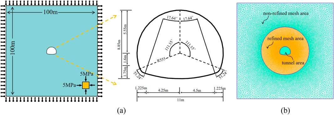
The model shown in Figure 6A was established using Gmsh software, and the calculations were performed using the MultiFracS finite-discrete element software. To avoid boundary effects, the model size was set to be sufficiently large, with the dimensions of 100 m × 100 m. The tunnel is located at the center of the model, and the cross-section is horseshoe-shaped, modeled based on the actual internal contour dimensions. The boundaries of the model were fixed in the normal direction, and both horizontal and vertical stresses were set to 5 MPa, while the self-weight of the model was neglected. As shown in Figure 6B, the model assumes isotropy, and local mesh refinement was applied near the tunnel. The model is divided into three regions: non-refined mesh area, refined mesh area, and tunnel area, with a total of 83,458 triangular mesh elements, allowing for a more accurate capture of the deformation and failure characteristics of the surrounding rock.
To simulate the excavation process of the tunnel face, the excavation core was initially assigned artificially high strength values to prevent yielding during the in-situ stress equilibrium process. After achieving equilibrium, the core modulus reduction method was used to gradually reduce the Young’s modulus and viscous damping of the rock mass in the tunnel zone, thereby simulating the short-term unloading effects of the rock mass ahead of the tunnel face in three dimensions (Farrokh et al., 2006).
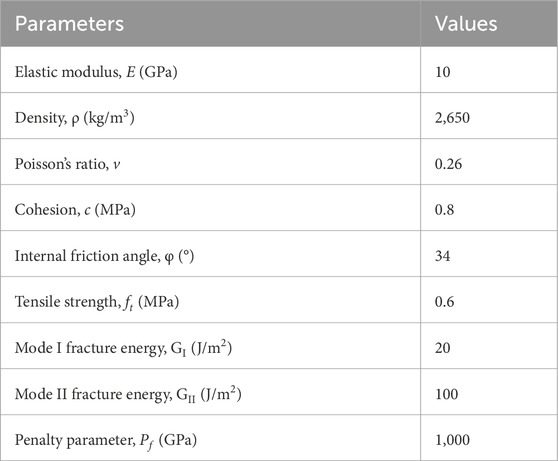
The FDEM input parameters are summarized in Table 1. The macroscopic parameters of the rock mass were derived from field experiments conducted at the Huotou Beishan Mega Tunnel. The microscopic parameters of the rock mass were obtained by inputting these macroscopic values into the MultiFracS software developed by Wang T. et al. (2023), Luo et al. (2023), Huang et al. (2023), Guo et al. (2024). A series of uniaxial compression tests were conducted, and iterative analysis and calibration were performed to determine these parameters.
4 Results and analysis
In the model shown in Figure 6, considering the in-situ stress under hydrostatic pressure (σ0) is set at 5 MPa, with the strength-stress ratio of the surrounding rock at Rc/σ0 = 5. According to the high in-situ stress classification standards in the “Engineering Rock Mass Classification Standards” (GB/T500218-2014), the in-situ stress is classified as high stress. Under the influence of this high stress, the crack propagation process in the weak surrounding rock is illustrated in Figure 7.
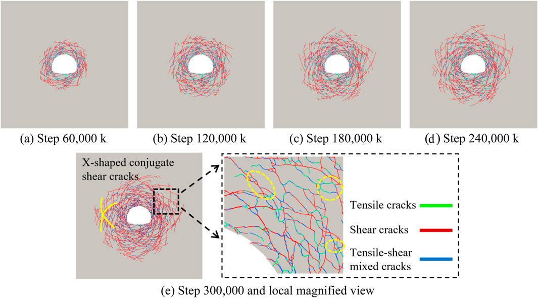
Figure 7. Crack evolution: (A) Step 60,000 k; (B) Step 120,000 k; (C) Step 180,000 k; (D) Step 240,000 k; (E) Step 300,000 k and local magnified view.
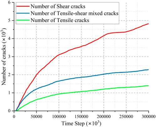
After the excavation of the tunnel, the in-situ stress is redistributed, resulting in localized stress concentrations. As shown in Figure 7, once the stress concentration exceeds the shear strength of the surrounding rock, tensile cracks, shear cracks, and mixed-mode cracks appear, forming a typical X-shaped conjugate shear fracture distribution around the tunnel. The crack propagation gradually reduces the overall strength of the surrounding rock, expanding deeper under compressive stress. From step 0 to 180,000, the crack propagation is rapid, then it slows and stabilizes at 300,000 steps. As shown in Figure 8, shear cracks dominate, indicating shear failure as the main mode. As shown in Figure 9, the crack expansion region is defined as the excavation damage zone (EDZ) (Doroodian et al., 2022), which appears nearly circular, similar to the full shear failure theoretical model proposed by Aydan et al. (1993), further validating the model’s rationality.
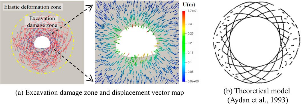
Figure 9. Failure characteristics of tunnel surrounding rock: (A) Excavation damage zone and displacement vector map; (B) Theoretical model (Aydan et al., 1993).
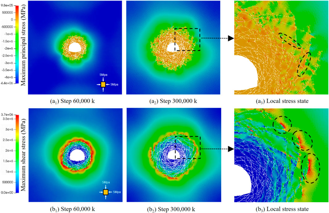
During the process of crack formation and propagation, the internal stress within the surrounding rock undergoes significant changes. In the initial stage of crack development, the maximum principal stress typically concentrates around the edges of the crack in the surrounding rock. As the crack extends deeper into the rock, the principal stress at the crack edges gradually increases, while the shear stress goes through a process of first increasing and then decreasing. This phenomenon is clearly illustrated in Figure 10, where the shear stress near the crack tip spreads in a wave-like pattern, resembling the diffusion of water ripples. The maximum shear stress is concentrated at the crack tip and gradually dissipates outward.
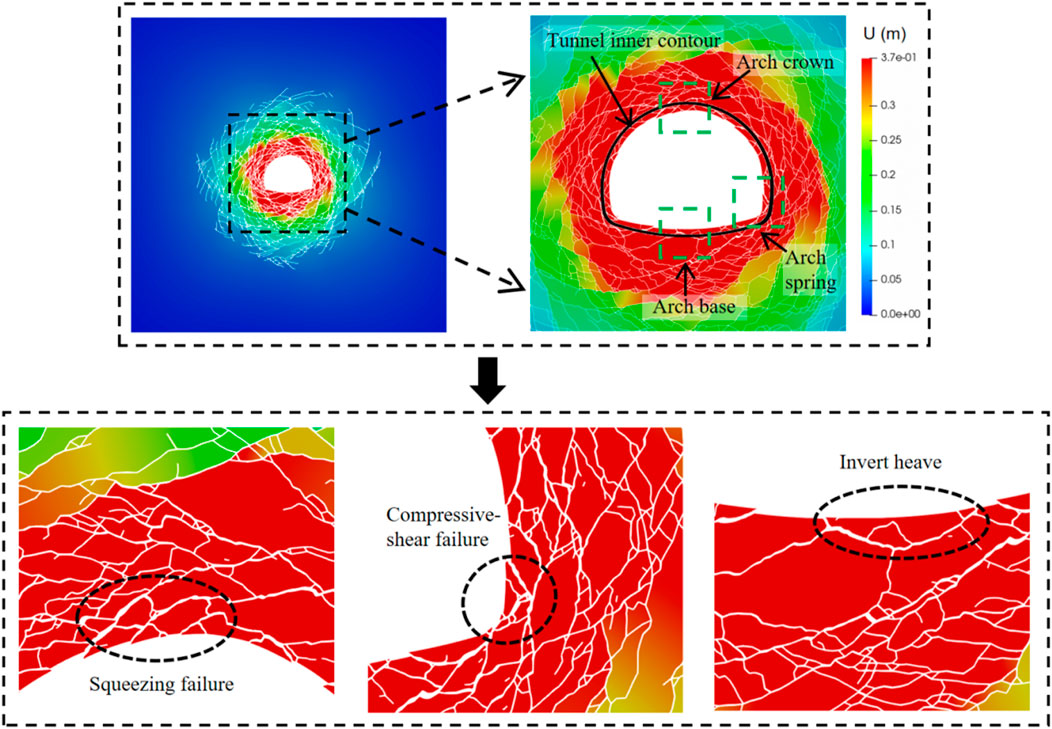
To explore the issue of surrounding rock intrusion, this section systematically analyzes the crack evolution process, stress state, and failure characteristics of the surrounding rock. As shown in Figure 11, the maximum displacement of the tunnel’s surrounding rock reaches 0.373 m. Under hydrostatic pressure, displacement is uniformly distributed along the tunnel’s inner contour. Localized stress concentration leads to the initial formation of shear cracks at the arch waist, which then extend toward the arch bottom and crown, eventually forming a typical “X”-shaped conjugate shear crack at the intersection. The propagation of cracks pushes deep rock fragments inward, reducing the cross-sectional area of the tunnel, resulting in compression-shear failure at the arch waist, squeezing failure at the crown, and invert heave.
5 Analysis of factors influencing large deformation in deep-buried soft rock tunnels
5.1 Influence of in-situ stress
To investigate the failure characteristics and patterns of soft rock tunnels under different burial depths, the in-situ stress was set to 3, 4, 5, 6, and 7 MPa, respectively, while maintaining hydrostatic pressure. The simulation results for an in-situ stress of 5 MPa are the same as those in Section 3.2, and the simulation results for the other stress conditions are shown in Figure 12.
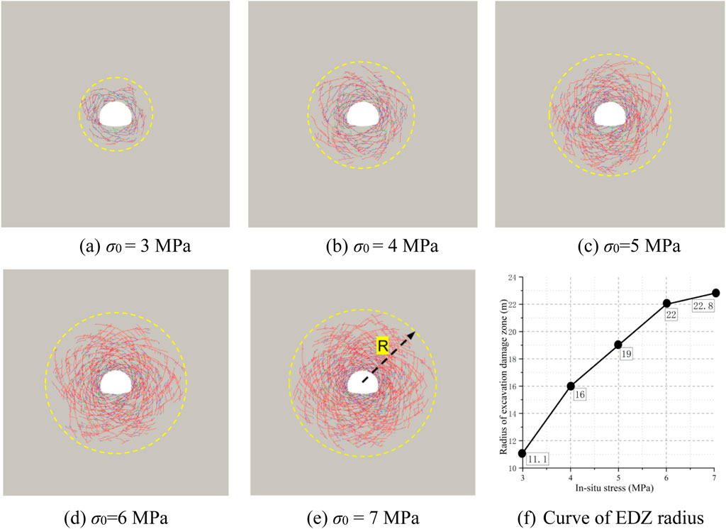
Figure 12. The effect of in-situ stress on the failure characteristics of surrounding rock: (A) σ0 = 3 MPa; (B) σ0 = 4 MPa; (C) σ0 = 5 MPa; (D) σ0 = 6 MPa; (E) σ0 = 7 MPa; (F) Curve of EDZ radius.
As illustrated in Figures 12A–E, variations in the in-situ stress had minimal effect on the failure characteristics, which consistently included X-shaped conjugate cracks, crown compression failure, arch waist shear failure, and invert heave. As in-situ stress increased, the excavation damage zone (EDZ) radius also increased (Figure 12G).
Figures 13, 14 show that the in-situ stress had a significant effect on the degree of failure of the surrounding rock, as evidenced by increased crack propagation and rock fragmentation. As the in-situ stress increased, the number, total area, and total length of cracks gradually increased, with shear cracks remaining dominant. At an in-situ stress of 3 MPa, the maximum shear stress just exceeded the shear strength of the rock, and a few X-shaped shear cracks developed without significant sliding along the shear plane, resulting in limited deformation. At 7 MPa, the intense shear stress extended the cracks deeper into the tunnel, with non-linear displacement patterns observed in the sections (Figure 14A), together with rock fragmentation at the tunnel surface (Figure 14B). Shattered shallow rock fragments squeezed into the tunnel surface, and collapse was more likely after support failure than mere deformation or cracking. This behavior was consistent with field observations (Figure 14C).
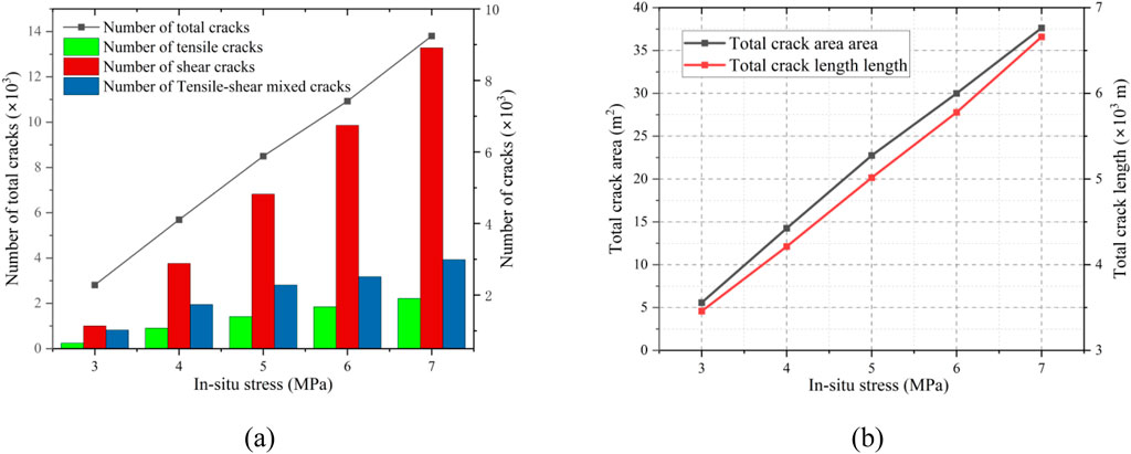
Figure 13. (A) The effect of in-situ stress on the number of cracks; (B) The effect of initial in-situ stress on the total length and total area of cracks.
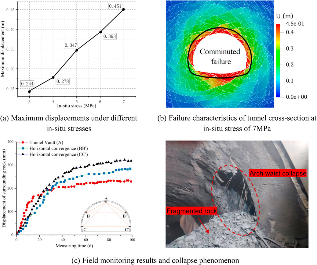
Figure 14. The effect of in-situ stress on maximum deformation and failure characteristics of tunnels: (A) Maximum displacements under different in-situ stresses; (B) Failure characteristics of tunnel cross-section at in-situ stress of 7 MPa; (C) Field monitoring results and collapse phenomenon.
5.2 Influence of lateral pressure coefficient
The direction of the maximum principal stress is a critical environmental factor that cannot be overlooked in tunnel support design. This section aims to provide a reference for support design in tunnel engineering under varying biaxial conditions by simulating failure modes of the surrounding rock at different lateral pressure coefficients. Based on a horizontal stress (σn) of 5 MPa, the vertical stress is set to 10, 6.67, 5, 4, and 3.33 MPa, corresponding to lateral pressure coefficients (λ = σn/σv) of 0.5, 0.75, 1.0, 1.25, and 1.5, respectively.
As shown in Figure 15, when the lateral pressure coefficient is not equal to 1, the shear cracks extend from the tunnel edges and adjust along the direction of the maximum principal stress, forming curved shapes. The crack pattern consists of multiple logarithmic spiral cracks that intersect, forming a V-shaped failure characteristic. The excavation damaged zone (EDZ) in the surrounding rock is elliptical, with the long and short axes extending along the directions of the minimum and maximum principal stresses, respectively. As the lateral pressure coefficient increases, the depth of rock failure (horizontal axis) decreases, while the length of the vertical axis increases. When the lateral pressure coefficient equals 1, the EDZ appears circular. Additionally, with increasing lateral pressure coefficients, the extent of rock failure decreases, leading to a reduction in the number, total area, and length of cracks (Figure 16).
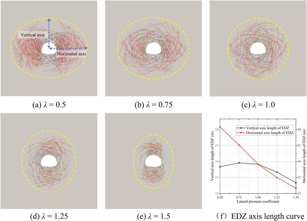
Figure 15. The effect of lateral pressure coefficient on the failure characteristics of the surrounding rock: (A) λ = 0.5; (B) λ = 0.75; (C) λ = 1.0; (D) λ = 1.25; (E) λ = 1.5; (F) EDZ axis length curve.
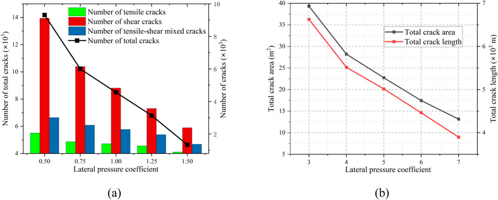
Figure 16. (A) The effect of lateral pressure coefficient on the number of cracks; (B) The effect of lateral pressure coefficient on the total length and total area of cracks.
From Figure 17 it can be seen that the concentrated damage zones of the rock surrounding the tunnel vary for different lateral pressure coefficients. When λ < 1, the concentrated damage zones are located at the arch waist and the sidewalls, and primarily exhibit compressive-shear failure (Figure 17A). In practical engineering, stress environments dominated by horizontal stresses are more likely to cause significant deformation on both sides of the tunnel, leading to primary support intrusion. When λ > 1, the concentrated damage shifts to the arch crown and invert, exhibiting compression failure and invert heave (Figure 17B). The observed crown frame collapse is consistent with a high lateral pressure coefficient scenario, indicating the need to strengthen the crown support in a gravitational stress-dominated environment.
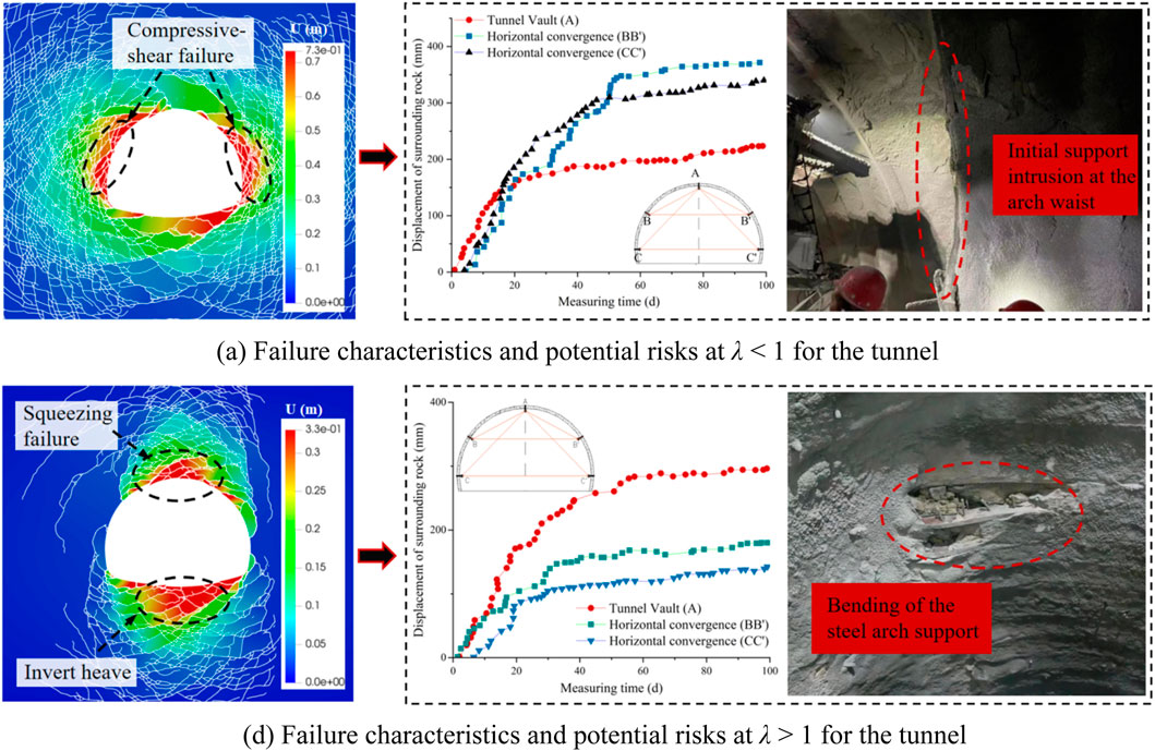
Figure 17. Failure characteristics of tunnels under different lateral pressure coefficients and the corresponding potential risks: (A) Failure characteristics and potential risks at λ < 1 for the tunnel; (B) Failure characteristics and potential risks at λ > 1 for the tunnel.
6 Conclusion
This study employed the finite-discrete element method (FDEM) using the MultiFracS software to simulate the large deformation mechanisms and processes in the weak surrounding rock of the Hutou Beishan Mega Tunnel. The effects of in-situ stress and lateral pressure coefficients on the large deformation of soft rock were analyzed. The main conclusions are as follows:
(1) The crack morphology is mainly X-shaped conjugate cracks, with three failure modes: shear compression failure, extrusion failure, and invert heave.
(2) Under hydrostatic conditions, the change of in-situ stress will aggravate the damage degree of the surrounding rock, but will not change the damage mode, while the change of lateral pressure coefficient under non-hydrostatic conditions will significantly change the concentrated damage zone.
(3) Based on the case of the Hutou Beishan Mega Tunnel, high in-situ stress under hydrostatic conditions can lead to rock fragmentation around the tunnel, resulting in a risk of collapse. The smaller the lateral pressure coefficient, the greater the risk of initial support intrusion on both sides of the tunnel, while when the lateral pressure coefficient is larger, the greater the risk of steel arch bending at the vault and invert heave.
Data availability statement
The original contributions presented in the study are included in the article/supplementary material, further inquiries can be directed to the corresponding author.
Author contributions
YW: Conceptualization, Investigation, Validation, Visualization, Writing–original draft. JQ: Conceptualization, Validation, Visualization, Writing–original draft. SZ: Formal Analysis, Project administration, Writing–review and editing. ZH: Formal Analysis, Resources, Writing–review and editing. YH: Data curation, Writing–review and editing. CY: Funding acquisition, Investigation, Methodology, Software, Supervision, Writing–review and editing.
Funding
The author(s) declare that financial support was received for the research, authorship, and/or publication of this article. This work was supported by the State Key Laboratory of Intelligent Construction and Healthy Operation and Maintenance of Deep Underground Engineering (Grant No. SKLGDUEK2206), and the National Natural Science Foundation of China (Grant No. 11872340).
Conflict of interest
Authors YW, JQ, SZ, and ZH were employed by Tianjin Municipal Engineering Design and Research Institute Co., Ltd.
The remaining authors declare that the research was conducted in the absence of any commercial or financial relationships that could be construed as a potential conflict of interest.
Generative AI statement
The author(s) declare that no Generative AI was used in the creation of this manuscript.
Publisher’s note
All claims expressed in this article are solely those of the authors and do not necessarily represent those of their affiliated organizations, or those of the publisher, the editors and the reviewers. Any product that may be evaluated in this article, or claim that may be made by its manufacturer, is not guaranteed or endorsed by the publisher.
References
Akgün, H., Muratlı, S., and Koçkar, M. K. (2014). Geotechnical investigations and preliminary support design for the Geçilmez tunnel: a case study along the Black Sea coastal highway, Giresun, northern Turkey. Tunn. Undergr. Space Technol. 40, 277–299. doi:10.1016/j.tust.2013.10.018
Aydan, Ö., Akagi, T., and Kawamoto, T. (1993). The squeezing potential of rocks around tunnels; Theory and prediction. Rock Mech. Rock Eng. 26 (2), 137–163. doi:10.1007/BF01023620
Chen, Z., He, C., Xu, G., Ma, G., and Yang, W. (2019). Supporting mechanism and mechanical behavior of a double primary support method for tunnels in broken phyllite under high geo-stress: a case study. Bull. Eng. Geol. Environ. 78, 5253–5267. doi:10.1007/s10064-019-01479-1
Deng, P., Liu, Q., Liu, B., and Lu, H. (2023). Failure mechanism and deformation prediction of soft rock tunnels based on a combined finite–discrete element numerical method. Comput. Geotech. 161, 105622. doi:10.1016/j.compgeo.2023.105622
Ding, X., Weng, Y., Zhang, Y., Xu, T., Wang, T., Rao, Z., et al. (2017). Stability of large parallel tunnels excavated in weak rocks: a case study. Rock Mech. Rock Eng. 50, 2443–2464. doi:10.1007/s00603-017-1247-6
Doroodian, B., Ahangari, K., and Noorzad, A. (2022). Damage caused by mechanized tunnel boring in high-stress hard rock. Transp. Geotech. 34, 100741. doi:10.1016/j.trgeo.2022.100741
Farrokh, E., Mortazavi, A., and Shamsi, G. (2006). Evaluation of ground convergence and squeezing potential in the TBM driven Ghomroud tunnel project. Tunn. Undergr. Space Technol. 21 (5), 504–510. doi:10.1016/j.tust.2005.09.003
Fu, S., Li, H., Liu, L., Wu, D., and Wang, B. (2024). Effect of intermittent joint distribution on the mechanical and acoustic behavior of rock masses. J. Rock Mech. Geotech. Eng. 16 (4), 1231–1244. doi:10.1016/j.jrmge.2023.07.013
Guo, H., Yan, C., Zhang, G., Xu, R., Wang, T., and Jiao, Y.-Y. (2024). Mechanical analysis of toppling failure using FDEM: a case study for soft-hard interbedded anti-dip rock slope. Comput. Geotech. 165, 105883. doi:10.1016/j.compgeo.2023.105883
Hu, Y., Yan, C., Jiao, Y.-Y., Wang, L., Jia, Y., and Wang, Y. (2025). Analysis and countermeasures of asymmetric failure in layered surrounding rock tunnels based on FDEM: a case study. Eng. Fail. Anal. 167, 109049. doi:10.1016/j.engfailanal.2024.109049
Huang, K., Dai, Z., Yan, C., and Chen, S. (2023). Numerical study on the swelling and failure of red-layer mudstone subgrade caused by humidity diffusion. Comput. Geotech. 156, 105272. doi:10.1016/j.compgeo.2023.105272
Li, Y., Zhang, D., Fang, Q., Yu, Q., and Xia, L. (2014). A physical and numerical investigation of the failure mechanism of weak rocks surrounding tunnels. Comput. Geotech. 61, 292–307. doi:10.1016/j.compgeo.2014.05.017
Lisjak, A., Garitte, B., Grasselli, G., Müller, H. R., and Vietor, T. (2015). The excavation of a circular tunnel in a bedded argillaceous rock (Opalinus Clay): short-term rock mass response and FDEM numerical analysis. Tunn. Undergr. Space Technol. 45, 227–248. doi:10.1016/j.tust.2014.09.014
Luo, Z., Yan, C., Ke, W., Wang, T., and Xiao, M. (2023). A surrogate model based on deep convolutional neural networks for solving deformation caused by moisture diffusion. Eng. Anal. Bound. Elem. 157, 353–373. doi:10.1016/j.enganabound.2023.09.009
Ma, Y., Sheng, Q., Zhang, G., and Cui, Z. (2019). A 3D discrete-continuum coupling approach for investigating the deformation and failure mechanism of tunnels across an active fault: a case study of xianglushan tunnel. Appl. Sci. 9 (11), 2318. doi:10.3390/app9112318
Munjiza, A., Bangash, T., and John, N. W. M. (2004). The combined finite–discrete element method for structural failure and collapse. Eng. Fract. Mech. 71 (4-6), 469–483. doi:10.1016/S0013-7944(03)00044-4
Sun, X., Zhao, C., Tao, Z., Kang, H., and He, M. (2021). Failure mechanism and control technology of large deformation for Muzhailing Tunnel in stratified rock masses. Bull. Eng. Geol. Environ. 80, 4731–4750. doi:10.1007/s10064-021-02222-5
Tang, H., Ji, X., Zhang, H., and Li, T. (2022). Numerical simulation of large compression deformation disaster and supporting behavior of deep buried soft rock tunnel with high in situ stress based on CDEM. Adv. Civ. Eng. 2022 (1), 5985165. doi:10.1155/2022/5985165
Wang, T., Yan, C., Wang, G., Zheng, Y., Ke, W., and Jiao, Y.-Y. (2022). Numerical study on the deformation and failure of soft rock roadway induced by humidity diffusion. Tunn. Undergr. Space Technol. 126, 104565. doi:10.1016/j.tust.2022.104565
Wang, T., Yan, C., Zheng, H., Ke, W., and Ali, S. (2023b). Optimum spacing and rock breaking efficiency of TBM double disc cutters penetrating in water-soaked mudstone with FDEM. Tunn. Undergr. Space Technol. 138, 105174. doi:10.1016/j.tust.2023.105174
Wang, Y., Liu, Y., Wang, Z.-F., Zhang, X., Hui, Y., and Li, J. (2023a). Investigation on progressive failure process of tunnel lining induced by creep effect of surrounding rock: a case study. Eng. Fail. Anal. 144, 106946. doi:10.1016/j.engfailanal.2022.106946
Wu, D., Fukuda, D., Min, G., Li, H., Liu, H., Ogata, S., et al. (2024). Development of a GPGPU-parallelized 3-D FDEM with a novel and simple implementation of extrinsic cohesive zone model. Comput. Geotech. 174, 106643. doi:10.1016/j.compgeo.2024.106643
Wu, D., Li, H., Fukuda, D., and Liu, H. (2023). Development of a finite-discrete element method with finite-strain elasto-plasticity and cohesive zone models for simulating the dynamic fracture of rocks. Comput. Geotech. 156, 105271. doi:10.1016/j.compgeo.2023.105271
Wu, D., Li, H., Shao, Z., Chen, S., Zhou, C., and Liu, L. (2021). Effects of infilling materials on mechanical behaviors and cracking process of pre-cracked rock: insights from a hybrid continuum-discontinuum method. Eng. Fract. Mech. 253, 107843. doi:10.1016/j.engfracmech.2021.107843
Wu, H., Fan, F., Yang, X., Wang, Z., Lai, J., and Xie, Y. (2022). Large deformation characteristics and treatment effect for deep bias tunnel in broken phyllite: a case study. Eng. Fail. Anal. 135, 106045. doi:10.1016/j.engfailanal.2022.106045
Yan, C., Guo, H., and Tang, Z. (2022). Three-dimensional continuous-discrete pore-fracture mixed seepage model and hydro-mechanical coupling model to simulate hydraulic fracturing. J. Pet. Sci. Eng. 215, 110510. doi:10.1016/j.petrol.2022.110510
Yan, C., and Jiao, Y.-Y. (2018). A 2D fully coupled hydro-mechanical finite-discrete element model with real pore seepage for simulating the deformation and fracture of porous medium driven by fluid. Comput. Struct. 196, 311–326. doi:10.1016/j.compstruc.2017.10.005
Yan, C., Jiao, Y.-Y., and Zheng, H. (2018). A fully coupled three-dimensional hydro-mechanical finite discrete element approach with real porous seepage for simulating 3D hydraulic fracturing. Comput. Geotech. 96, 73–89. doi:10.1016/j.compgeo.2017.10.008
Yan, C., Xie, X., Ren, Y., Ke, W., and Wang, G. (2022). A FDEM-based 2D coupled thermal-hydro-mechanical model for multiphysical simulation of rock fracturing. Int. J. Rock Mech. Min. Sci. 149, 104964. doi:10.1016/j.ijrmms.2021.104964
Yan, C., Zhao, Z., Yang, Y., and Zheng, H. (2023a). A three-dimensional thermal-hydro-mechanical coupling model for simulation of fracturing driven by multiphysics. Comput. Geotech. 155, 105162. doi:10.1016/j.compgeo.2022.105162
Yan, C., and Zheng, H. (2016). A two-dimensional coupled hydro-mechanical finite-discrete model considering porous media flow for simulating hydraulic fracturing. Int. J. Rock Mech. Min. Sci. 88, 115–128. doi:10.1016/j.ijrmms.2016.07.019
Yan, C., and Zheng, H. (2017a). FDEM-flow3D: a 3D hydro-mechanical coupled model considering the pore seepage of rock matrix for simulating three-dimensional hydraulic fracturing. Comput. Geotech. 81, 212–228. doi:10.1016/j.compgeo.2016.08.014
Yan, C., and Zheng, H. (2017b). Three-Dimensional hydromechanical model of hydraulic fracturing with arbitrarily discrete fracture networks using finite-discrete element method. Int. J. Geomech. 17 (6), 04016133. doi:10.1061/(asce)gm.1943-5622.0000819
Yan, C., Zheng, Y., and Wang, G. (2023b). A 2D adaptive finite-discrete element method for simulating fracture and fragmentation in geomaterials. Int. J. Rock Mech. Min. Sci. 169, 105439. doi:10.1016/j.ijrmms.2023.105439
Zhan, Q., Zheng, X., Du, J., and Xiao, T. (2020). Coupling instability mechanism and joint control technology of soft-rock roadway with a buried depth of 1336 m. Rock Mech. Rock Eng. 53, 2233–2248. doi:10.1007/s00603-019-02027-9
Zhao, J., Tan, Z., Yu, R., Li, Z., and Wang, X. (2023). Mechanical responses of a shallow-buried super-large-section tunnel in weak surrounding rock: a case study in Guizhou. Tunn. Undergr. Space Technol. 131, 104850. doi:10.1016/j.tust.2022.104850
Keywords: large deformation of soft rock, deep tunnel, FDEM, excavation damage zone (EDZ), MultiFracS
Citation: Wang Y, Qiao J, Zheng S, He Z, Hu Y and Yan C (2024) Application of FDEM in the study of large deformation mechanisms in deep-buried soft rock tunnels: A case study. Front. Earth Sci. 12:1517816. doi: 10.3389/feart.2024.1517816
Received: 27 October 2024; Accepted: 28 November 2024;
Published: 23 December 2024.
Edited by:
Huaming An, Kunming University of Science and Technology, ChinaReviewed by:
Hongbo Du, Chongqing Jiaotong University, ChinaJinhao Dai, Southeast University, China
Di Wu, Changjiang Institute of Survey, Planning, Design and Research Co., Ltd., China
Haoyu Han, Yunnan University, China
Copyright © 2024 Wang, Qiao, Zheng, He, Hu and Yan. This is an open-access article distributed under the terms of the Creative Commons Attribution License (CC BY). The use, distribution or reproduction in other forums is permitted, provided the original author(s) and the copyright owner(s) are credited and that the original publication in this journal is cited, in accordance with accepted academic practice. No use, distribution or reproduction is permitted which does not comply with these terms.
*Correspondence: Chengzeng Yan, eWFuY3pAY3VnLmVkdS5jbg==
 Yanning Wang1
 Chengzeng Yan
